Controllable thermal rectification design for buildings based on phase change composites
2024-03-02HengbinDingXiaoshiLiTianhangLiXiaoyongZhaoandHeTian
Hengbin Ding ,Xiaoshi Li ,Tianhang Li ,Xiaoyong Zhao ,and He Tian,†
1School of Integrated Circuits and Beijing National Research Center for Information Science and Technology (BNRist),Tsinghua University,Beijing 100084,China
2Zhuhai Huafa Properties Co.,Ltd,Zhuhai 519030,China
Abstract: Phase-change material (PCM) is widely used in thermal management due to their unique thermal behavior.However,related research in thermal rectifier is mainly focused on exploring the principles at the fundamental device level,which results in a gap to real applications.Here,we propose a controllable thermal rectification design towards building applications through the direct adhesion of composite thermal rectification material (TRM) based on PCM and reduced graphene oxide(rGO) aerogel to ordinary concrete walls (CWs).The design is evaluated in detail by combining experiments and finite element analysis.It is found that,TRM can regulate the temperature difference on both sides of the TRM/CWs system by thermal rectification.The difference in two directions reaches to 13.8 K at the heat flow of 80 W/m2.In addition,the larger the change of thermal conductivity before and after phase change of TRM is,the more effective it is for regulating temperature difference in two directions.The stated technology has a wide range of applications for the thermal energy control in buildings with specific temperature requirements.
Key words: phase change composites;controllable thermal rectification;building applications
1.Introduction
Tropical regions and cold-temperate zones maintain high and low temperatures outside for long time.The extreme climate has a considerable impact on the activities of the inhabitants[1],who spend most of their time indoors.In order to maintain a comfortable indoor temperature,the building envelopes in these regions are usually designed with thermal insulation features[2].However,traditional insulation materials completely block the heat transfer between indoor and outdoor,which also hinder building heat dissipation at night in tropical regions and building heat absorption at noon in cold-temperate zones.This means that a building structure is needed that controls the directional heat transfer,which allows heat conduction in one direction and heat cut-off in the opposite direction (Fig.1(a)).Henryetal.[3]proposed that building envelopes with variable thermal conductivity could save 7%-42% of energy consumption in buildings,thus effectively reducing greenhouse gas emissions and achieving low carbon development.In recent years,thermal rectifiers have shown great prospect in thermal management and energy saving applications due to their ability to actively control heat transfer[4].

Fig.1.(Color online) (a) Schematic diagram of the directional heat transfer mechanism.(b) System schematic of TRM applied in building.(c) Evaluation framework of this work.(d) Schematic diagram of the thermoelectric coupling system in the simulation.
For microscale thermal rectifiers,the first solid-state thermal rectifier based on a single carbon nanotube has been reported experimentally[5],just four years after the simulation result was reported.Recently,more attention has been focused on controlling heat transport through defect engineering[6-8]and nanostructures[9,10].Although various nanostructures have been theoretically predicted to achieve the thermal rectification effects,they usually face design and fabrication challenges[11].For macroscopic scale thermal rectifiers,there are fewer related studies.Up to now,the simple design of thermal rectifier was based on a two-segment materials[12].There are two basic ideas to achieve thermal rectification:The two materials have different temperature dependence of thermal conductivity[13]and stress-induced interfacial thermal contact resistance[14],and both methods achieve the thermal rectification effect with high thermal conductivity in the positive direction and low thermal conductivity in the negative direction.For the single material,such as rGO paper,building an asymmetric shape can also achieve the macroscale thermal rectification effect[15].Overall,although these accomplishments offered exciting prospects,they mainly concentrated on fundamental research at the theoretical level.The gap between fundamental research and real applications still needs to be filled by evaluation studies for specific applications.
In contrast to the thermal rectifiers mentioned above,we propose a macroscopic thermal rectification design for buildings (Fig.1(b)),which is achieved by the direct adhesion of thermal rectification material (TRM) to concrete walls (CWs).The design is also evaluated in detail with experiments and simulations (Fig.1(c)).Compared to conventional insulation,TRM has variable thermal conductivity,meaning that thermal rectification can be turned on at a specific temperature range and the thermal rectification coefficient can be adjusted.This allows TRM to effectively control the directional heat transfer and regulate the temperature difference on both sides of system based on temperature changes.TRM is composed of two parts: the nano-porous skeleton and phase change material (PCM).The skeleton is used to prevent PCM leakage[16].In this work,reduced graphene oxide(rGO) aerogel[17]is chosen as the skeleton and eicosane is chosen as PCM.
Fig.1(d) shows the schematic diagram of thermoelectric coupling system and defines the positive and negative directions of heat flow.With the same heat flow in the positive and negative directions,we define system the thermal rectification coefficientR:
Here ΔT+is the temperature difference established by the positive heat flow (J+) and ΔT-is the temperature difference established by the negative heat flow (J-).For the system without thermal rectification effect,R=1,which means that the same magnitude of heat flow produces the same temperature gradient.For the system with thermal rectification effect,R>1,that is,same magnitude of heat flow produces the different temperature gradient.The larger value ofR,the stronger thermal rectification effect.
In the following,to obtain the ideal thermal rectification performance achieved by TRM adhered to CWs and to evaluate the application effects of this design,we proceed as follows (Fig.1(c)): First,we conduct a series of experimental measurements on the thermal performance of TRM and the thermal rectification performance of this design;Then,the ideal system (TRM/CWs) is established by COMSOL program and the physical parameters of system are calibrated based on experimental data;Finally,the mechanism of the thermal rectification effect is discussed and the universality of this design in various conditions is fully analyzed.
2.Experiments and method
The schematic diagram of TRM is shown in Fig.2(a).TRMs are prepared using the physical adsorption method by compositing rGO aerogel with eicosane.The rGO aerogels are prepared by thermal reduction and freeze-drying methods.During heating,the phase change process occurs and the thermal conductivityλdecreases significantly from about 0.4 to 0.16 W/(m∙K) when temperature reaches near the melting point of eicosane (Fig.2(b)).It is worth noting that the key to achieve thermal rectification is the significant saltation of thermal conductivity,rather than heat absorption during phase change.In addition,rGO aerogel can absorb more than 96% of eicosanes without leakage during the phase change process due to its three-dimensional (3D) interconnected porous network and high porosity (Fig.2(c)).Fig.2(d)is the cross-sectional SEM image of TRM,which shows that the composite system exhibits a spiderweb-like interconnected structure.The eicosanes were impregnated into the interior of rGO aerogel and filled the lamellar space.The pores and abundant capillaries of the 3D skeleton effectively adsorbed and firmly bound the organic phase by intermolecular forces.Fig.2(e) shows the differential scanning calorimetry (DSC) test plot.It can be found that the phase change temperature of TRM is only 0.3 °C lower than pure eicosane and the enthalpy drop is slightly higher than pure eicosane(13.4 J/g).This indicates that the crystallinity of eicosane molecules within rGO aerogel has not changed significantly,and the intermolecular interactions between rGO layer and highly dispersed eicosane have intensified the enthalpy drop of eicosane[18].Therefore,rGO aerogel mainly provides adsorption sites for eicosane molecules as a 3D skeleton,which prevents leakage during phase change process and hardly affects the thermal properties of eicosane.

Fig.2.(Color online) (a) Structure schematic of composite TRM.(b) Thermal conductivity versus temperature curve of TRM.(c) SEM images of rGO aerogel skeleton.(d) SEM images of rGO aerogel filled with eicosanes.(e) DSC curves of eicosane and TRM.(f) Calibration of thermal rectification curves to experimental data.Experimental data are from a thermal rectification system with the CW thermal conductivity of 0.57 W/(m∙K).
During thermal rectification testing,the inevitable heat exchange between heater and outside and the uncontrollable contact thermal resistance between different materials lead to an unavoidable deviation of thermal rectification.In order to investigate the potential advantages of the thermal rectification design for buildings,a thermoelectric coupling system with ideal heat exchange and mutual contact is established in the simulation.When current flows,the heater generates joule heat to provide a heat source for TRM/CWs system.Assuming that heat is transferred only through TRM/CWs system,and is only exchanged with outside through thermal radiation and thermal convection at the low temperature end.This means that heater power per unit area is equivalent to heat flow intensity.In order to ensure sufficient accuracy and reduce calculation costs,we only consider the steady-state case when calculatingR.
For this system,the considered material properties contain the value of melting point,thermal conductivity,latent heat,mainly from the experimental results mentioned above,and the considered boundary conditions are calibrated by the experimental results ofR(Fig.2(f)),which were measured by the self-built test system.The direction and magnitude of heat flow were changed by adjusting the position and heating power of heating patch.The steady-state temperature differences established in the two directions were measured by micro thermocouple at the same heat flow magnitude respectively,andRwas calculated according to Eq.(1).Using the calibrated system parameters,we investigate the thermal rectification design to understand the thermal rectification mechanism and analyze the universality.Table 1 summarizes the relevant parameters used in this work,which are added to the parameter file to simulate the thermal rectification effect.

Table 1.The relevant parameters used in this work.
3.Results and discussion
Fig.3(a) shows the relationship between heat flow andRfor different thickness of TRMs.In order to make the system close to the real applications,the thickness of CWs is set to 20 cm.When heat flow is below 46 W/m2,Ris a constant 1.0,indicating that there is no thermal rectification effect in TRM/CWs system.When heat flow continues to increase and eicosane begins to melt,the thermal rectification curve enters the amplification region,andRincreases rapidly with increase of heat flow,which indicates that the phase change of TRM works as a switch to control the on/off of thermal rectification.When the curve enters the saturation region,a plateau occurs.As the thickness of TRM increases,the range of amplification region increases andRis larger.As heat flow continues to increase,the thermal rectification curve enters the decay region andRbegins to decrease.This is because eicosane on the low temperature side partially melts in theJ-,resulting in a decrease of the difference in ΔT+and ΔT-generated byJ+andJ-.It is worth noting that as the thickness of TRM increases,heat flow required to turn on thermal rectification and the range of saturation region is smaller because greater thickness is more likely to accumulate heat to make part of TRM reach its melting point.Overall,thermal rectification effect can be activated by solid-to-liquid phase change andRcan be adjusted by different heater power.With heat flow of same magnitude and opposite direction (J+andJ-),the temperature difference between two sides of the TRM/CWs system differs due to thermal rectification effect.The thermal resistance in theJ+direction is higher,resulting in a greater temperature difference (Fig.3(b)).For practical applications,in tropical regions,TRM is adhered to the outside of building walls.During the day,TRM melts into liquid state,preventing heat entering the building from the outside.At night,when the outside temperature is lower than the inside,the TRM radiates heat to the outside and converts to solid state,allowing indoor heat to dissipate to the outside.Similarly,in cold-temperate regions,TRM is adhered to the inside of building walls to prevent heat dissipation at night and allow heat to enter during the day.

Fig.3.(Color online) Thermal rectification performance and mechanism in the TRM/CWs system.(a) Thermal rectification coefficient R vs.heat flow curves.The thickness of CWs is 20 cm,and the thickness of TRM is 1,2,3,4,and 5 cm respectively.(b) Compared to pure CWs,temperature difference established on both sides of the TRM/CWs system vs.heater power (heat flow) curves in the J+ and J- directions.The thickness of TRM is 1,3,and 5 cm respectively.Temperature distribution (c) and temperature curves (d) in the J+ and J- directions,where the heat flow is 98 W/m2.
The mechanism of thermal rectification is based on the instantaneous saltation of thermal conductivity generated by TRM during the phase change process.As shown in Fig.3(c),the temperature distribution of TRM/CWs system is mainly concentrated in the TRM region in theJ+,because TRM is more prone to phase change and exhibits low thermal conductivity in the liquid state.In theJ-,the TRM is more difficult to undergo phase change and exhibits high thermal conductivity in the solid state,thus temperature distribution of the TRM/CWs system is more uniform.In addition,there is a significant temperature difference at the heating end when setting same temperature at the low temperature end (Fig.3(d)).This indicates thatJ+requires more heating power thanJ-to establish same temperature at the low temperature end.It implies a higher positive thermal resistance and a lower negative thermal resistance,which also indicates the existence of thermal rectification effect in this system.
To verify the universality of this design for thermal energy control in buildings.We also analyzed the influence of physical properties of TRMs and CWs onR.Four TRMs and three CWs are defined in Fig.4(a).The physical parameters of TRM group include two different melting points and three different solid-state thermal conductivities,which correspond to different phase change composites.The physical parameters of CWs group include three different solid-state thermal conductivities,which correspond to three types of wall materials.The four lines in Fig.4(b) represent the relationship betweenRand heat flow.The larger change of thermal conductivity before and after phase change of TRM,the higherR.And the heater power (heat flow) for turning on thermal rectification can be adjusted by selecting TRMs with different melting points.As shown in Fig.4(c),the higherR,the more effective it is for regulating temperature difference in theJ+andJ-directions.It reaches 13.8 K (TRM4) at the heater power of 80 W/m2,i.e.,ΔT(Fig.1(a)) is 13.8 K.Furthermore,the thermal rectification curves vary for different CWs (Fig.4(d)).The larger the thermal conductivityλof CWs,the wider the range of amplification region and the narrower the range of saturation region.Table 2 shows the comparison for temperature control performance of different thermal insulation materials with the thickness of 4 cm,where heat flow is taken as 79 W/m2.This corresponds to a steady-state case where TRM4 maintains the indoor temperature of 296.26 K (comfort temperature for human body) at the outdoor temperature of 326.54 K.Obviously,compared to conventional insulation materials and pure rGO aerogels,TRM can effectively control the directional heat transfer via the variable thermal conductivityλof PCM and regulate the temperature difference on both sides of the TRM/CWs system,which enables ΔT(Fig.1(a)) to reach to 12.62 K,i.e.,Rto 1.71.

Table 2.The comparison for temperature control performance of different thermal insulation materials.
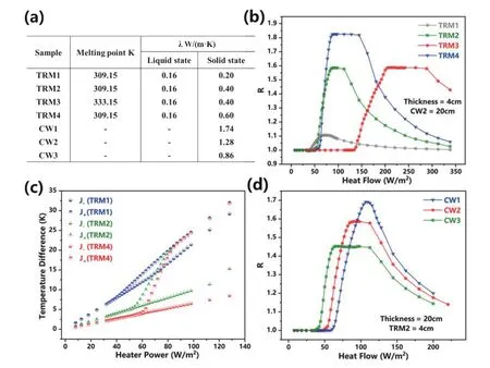
Fig.4.(Color online) Influence of physical properties of TRMs and CWs on R.(a) The physical properties of different TRM and CW in the simulation.(b) Thermal rectification coefficient R vs.heat flow curves for TRM (1-4).(c) Temperature difference established on both sides of the TRM/CWs system vs.heater power (heat flow) curves in the J+ and J- directions.(d) Thermal rectification coefficient R vs.heat flow curves for CW(1-3).
4.Conclusion
In this work,we propose and evaluate a macroscopic controllable thermal rectification design towards building applications.TRM is adhered to ordinary CWs to achieve efficient controllable thermal rectification,and thermal rectification coefficientRand scope of work can be modified by adjusting heater power and physical properties of materials.TRM can effectively control the directional heat transfer and regulate the temperature difference on both sides of the TRM/CWs system.The differences (ΔT) in two directions can reach to 13.8 K at the heat flow of 80 W/m2.Finally,the advantages of this design are compared with conventional insulation.The stated technology can be widely applied in the thermal control of smart building with specific temperature requirements.Acknowledgments
This work was supported in part by Tsinghua University-Zhuhai Huafa Industrial Share Company Joint Institute for Architecture Optoelectronic Technologies (JIAOT KF202204),in part by STI 2030–Major Projects under Grant 2022ZD0209200,in part by National Natural Science Foundation of China under Grant 62374099,Grant 62022047,in part by Beijing Natural Science-Xiaomi Innovation Joint Fund under Grant L233009,in part by the Tsinghua-Toyota JointResearch Fund,in part by the Daikin-Tsinghua Union Program,in part sponsored by CIE-Tencent Robotics XRhino-Bird Focused Research Program.
杂志排行

Journal of Semiconductors的其它文章
- Efficient flexible dye-sensitized solar cells from rear illumination based on different morphologies of titanium dioxide photoanode
- An advanced theoretical approach to study super-multiperiod superlattices: theory vs experiments
- Two-step growth of β-Ga2O3on c-plane sapphire using MOCVD forsolar-blind photodetector
- Controllable step-flow growth of GaN on patterned freestanding substrate
- Enhanced thermal emission from metal-free,fully epitaxial structures with epsilon-near-zero InAs layers
- Research progress of alkaline earth metal iron-based oxides as anodes for lithium-ion batteries