Efficient flexible dye-sensitized solar cells from rear illumination based on different morphologies of titanium dioxide photoanode
2024-03-02ZheHeGentianYueYueyueGaoChenDongandFuruiTan
Zhe He ,Gentian Yue,2,† ,Yueyue Gao ,Chen Dong ,and Furui Tan,†
1School of Future Technology and Henan Key Laboratory of Photovoltaic Materials,Henan University,Kaifeng 475004,China
2Zhenjiang Mars Photoenergy Technology Co.,Ltd,Zhenjiang 212011,China
Abstract: The TiO2 with nanoparticles (NPs),nanowires (NWs),nanorods (NRs) and nanotubes (NTs) structures were prepared by using a in-situ hydrothermal technique,and then proposed as a photoanode for flexible dye-sensitized solar cell (FDSSC).The influences of the morphology of TiO2 on the photovoltaic performances of FDSSCs were investigated.Under rear illumination of 100 mW∙cm-2,the power conversion efficiencies of FDSSCs achieved 6.96%,7.36%,7.65%,and 7.83% with the TiO2 photoanodes of NPs,NWs,NRs,and NTs and PEDOT counter electrode.The FDSSCs based on TiO2 NRs and NTs photoanodes have higher short circuit current densities and power conversion efficiencies than that of the others.The enhanced power conversion efficiency is responsible for their nanotubes and rod-shaped ordered structures,which are more beneficial to transmission of electron and hole in semiconductor compared to the TiO2 nanoparticles and nanowires disordered structure.
Key words: dye-sensitized solar cells;photoanode;TiO2;morphology
1.Introduction
Dye-sensitized solar cells (DSSCs) with economy,environmental friendliness,mechanical stability,simple preparation process,and high efficiency of 14%,are considered as a favorable choice compared to the silicon device[1-3].As an important component of DSSC,photoanode is not only a support and adsorption carrier for dye molecules,but also an electron transport carrier.Titanium dioxide (TiO2) is the most representative for its rich optical,dielectric,catalytic,and antimicrobial properties,which leads to a variety of uses in solar cells,photocatalytic,and fuel cells[4-7].Among three polymorphs of rutile,anatase,and brookite,rutile TiO2has more stable physicochemical properties,higher refractive index and lightscattering capability compared to anatase[8-10].Also,the morphology of TiO2shows significant effect on its physical and chemical properties,such as the one-dimensional (1-D) structure,whose charge transport is preferred compare to the mesoporous structure due to the reduction in grain boundaries and lattice imperfections,thereby slowing down the electron hole recombination rate and accelerating electron transfer,and helping to improve the performance of various optoelectronic applications[11-13].Sadhuet al.reported the fabrication of a three-dimensional (3-D) rutile-phase TiO2microsphere arrays on fluorine-doped conducting oxide (FTO),and showed superior photon-harvesting performance owing to the increase in light-scattering in DSSC[14].Riet al.spotlighted growth of a sea urchin-like rutile TiO2hierarchical microsphere on Ti foil,which showed much better light-scattering capability in visible region than the bare Ti foil[15].Sunet al.recorded a bilayer DSSC with an efficiency of 7.2% based on a bilayer TiO2film consisting of a 1-D nanowire arrays as underlayer and a 3-D dendritic microsphere as light-scattering overlayer[16].These results indicate that designing DSSC photoanodes with different morphologies is of great significance for improving the performance of DSSC.
Moreover,the substrate of traditional DSSC is FTO,and its features of rigid and heavy can not meet all application scenarios[17].To solve this issue,some flexible substrates (e.g.,ITO/PET,ITO/PEN and metals) are used to replace FTO glass.Nevertheless,the ITO/PET and ITO/PEN substrates are highcost and intolerant of temperatures higher than 150 °C,which is much lower than the temperature required for manufacturing photoanodes on FTO glass (450-500 °C),thus resulting in the relatively poor performance of plastic-based DSSCs.Therefore,high-temperature resistant metal foils (such as Ti and stainless steel) are used to fabricate flexible DSSCs(FDSSCs) with encouraging performance compared with the plastic-based ones[18,19].
In this contribution,the anatase phase TiO2with four morphologies of nanoparticles,nanowires,nanorods and nanotubes (abbreviated as NP,NW,NR and NT) were prepared by using ain-situhydrothermal synthesis and served as photoanode in FDSSCs.The influences of the morphology of TiO2on the adsorption capacity of dyes and charge transfer performances of FDSSCs were extensively investigated.The power conversion efficiencies of the FDSSCs based on NP,NW,NR,and NT TiO2photoanodes and poly (3,4-ethylenedioxythiophene)(PEDOT)counter electrode reached 6.96%,7.36%,7.65%,and 7.83%,respectively under rear illumination of 100 mW∙cm-2and the optimized condition.
2.Experimental
2.1.Various TiO2 photoanode preparation
A reserved thin TiO2blocking layer was prepared by immersing the Ti substrate in 0.15 M of TiCl4isopropanol solution for 12 h,followed by sintering at 450 °C for 30 min in air.
Next,four TiO2photoanodes with different morphologies were prepared.
(1) TiO2NPs paste were prepared as described previously[20-22].
(2) TiO2NRs were prepared as following[23-25].5 mL Tetrabutyltitanate was rapidly added to 75 mL absolute ethyl alcohol under stirring for 0.5 h and followed by addition of 0.33 mL concentrated sulfuric acid and 0.3 mL deionized water to the solution,and then transferred into 100 mL Teflon-liner and autoclaved at 180 °C for 4 h to form a milky white slurry.The slurry was dissolved into 50 mL,10 M NaOH solution.After ultrasonication and stirring for 0.5 h until a homogeneous solution was achieved and then the obtained solution was transferred into Teflon-liner and autoclaved at 150 °C for 24 h.The precipitate was collected by filter and washed with distilled water and 0.3 M HCl for 3 times,followed by washing with distilled water some times and annealing at 450 °C for 1 h.
(3) TiO2NTs were prepared in a two-steps hydrothermal method[26,27].3 g P25 powder was added into 10 M NaOH solution and then transferred into 100 mL Teflon-liner and autoclaved at 160 °C for 4 h and 110 °C for 20 h,respectively.After that,the obtained produce was washed with distilled water and HCl aqueous solution (pH=2),and then with distilled water for several times until the pH is 7.The products were calcined at 400 °C in air for 1 h.Thus the TiO2NTs were obtained.
The TiO2NRs and NTs paste were prepared including of 10 mL absolute ethyl alcohol,5 mL N-methyl-2-pyrrolidone,0.1 g polyvinylidene fluoride,1 g TiO2NRs and NTs kept stirring for 12 h at 50 °C.Soon afterwards,the TiO2NPs,NRs,and NTs films were coated onto the preprepared blocking layer by using doctor blade method,and then sintered at 450 °C for 30 min in air.
(4) TiO2NWs photoanode were prepared as the reported[28-30].10 mL dioxane and 1 mL HCl with concentrated of 35% were mixed with stirring,and then added 1 mL titanium butoxide and TiCl4to above solution.The obtained solution was transferred into a 25 mL Teflon-liner.The Ti substrate with a thin TiO2blocking layer was placed into above solution at an angle against the wall,and the hydrothermal synthesis was conducted at 180 °C for 6 h.The TiO2NWs photoanode was obtained.
At last,the dye was loaded by immersing the bilayer TiO2photoanodes in 0.3 mM of N719 ethanol solution for 12 h.Thus the flexible dye-sensitized TiO2photoanodes with thickness of 4-5μm was obtained.
2.2.Fabrication of FDSSCs
The PEDOT counter electrode (CE) was electropolymerization from the base polymerization solution consisted of 0.1 M EDOT,0.1 M LiClO4and PEG-600 dissolved in anhydrous ethanol.The FDSSCs assembled by clipping the dye-sensitized TiO2photoanode and Pt CE,and the liquid electrolyte consisted of 0.05 M of iodine,0.1 M of lituium iodide,0.6 M of tetrabutylammonium iodide and 0.5 M of 4-tert-butyl-pyridine in acetonitrile was injected in the aperture between the two electrodes.
2.3.Characterization
The morphology,microstructure and the elements of the samples were investigated by the transmission electron microscopy (TEM,JEM-2100F,Japan) equipped with energy dispersive spectrometer (EDS) and the field emission scanning electron microscopy (SEM,JSM-7001F,Japan).The crystalline structures of the composites were investigated by glancing incident X-ray diffractometer (X‘Pert Pro,PANalytical B.V.,Netherlands).The photovoltaic tests of FDSSCs with an exposed area of 0.2 cm2were carried out by measuring photocurrent-photovoltage (J-V) characteristic curves under rear irradiation of 100 mW∙cm-2from the solar simulator (CELS500,Beijing China Education Au-light Co.,Ltd) in ambient atmosphere.
3.Results and discussions
Fig.1 shows the SEM images of the TiO2NPs,NWs,NRs,and NTs.Figs.1(a)-1 and 1(a)-2 present the porous and loose nanostructure of TiO2NPs,and the Figs.1(b)-1 and 1(b)-2 exhibit a mixture of TiO2NWs and NPs,which are beneficial for the charge transfer and electrolyte loading.To compare the effect of the TiO2morphology on electron transfer,TiO2NRs and NTs were prepared and as shown as in Figs.1(c) and 1(d).From Figs.1(c)-1 and 1(c)-2,the TiO2NRs with different sizes and lengths can be observed clearly.Compared to TiO2NRs,TiO2NTs with a similar size and length are shown in Figs.1(d)-1 and 1(d)-2.In a word,the TiO2photoanode with nano-structure provides highly effective contact between the CE and theI–/I3–redox couple electrolyte,thus possibly absorbing more liquid electrolyte and improving the penetration ofI-/I3-liquid electrolyte within TiO2film,and expecting to obtain an excellent performance for FDSSC.

Fig.1.SEM images of TiO2 (a) NPs,(b) NWs,(c) NRs,and (d) NTs.
Fig.2 displays the XRD patterns of the TiO2NPs,NWs,NRs,and NTs photoanode.From Fig.2,the characteristic peaks for the TiO2NPs (2θ= 25.3°,37.8°,48.0°,53.8°,55.1°,and 62.6°),TiO2NWs (2θ= 25.5°,38.1°,48.3°,54.2°,55.3°,and 63.0°),TiO2NRs (2θ= 25.7°,38.4°,48.7°,54.3°,55.5°,and 63.2°),and TiO2NTs (2θ= 26.1°,38.6°,48.8°,54.7°,55.9°,and 63.5°) associated with the anatase phase are observed in all the XRD patterns[29,30].These findings demonstrate that the TiO2NPs,NWs,NRs,and NTs we synthesized are titania anatase dioxide.

Fig.2.(Color online) XRD patterns of TiO2 NPs,NWs,NRs,and NTs.
Fig.3 and Table 1 show the N2adsorption isotherm of the the TiO2NPs,NWs,NRs,and NTs and the specific surface area are about 91.9122,116.6744,126.3625,and 158.8077 m2/g,respectively.The large specific surface area for the TiO2NRs and NTs,which may be the key factors to absorb more dyes and enhance the performance for FDSSC.

Table 1.The absorption–desorption isotherm values of the TiO2 with different morphologies.
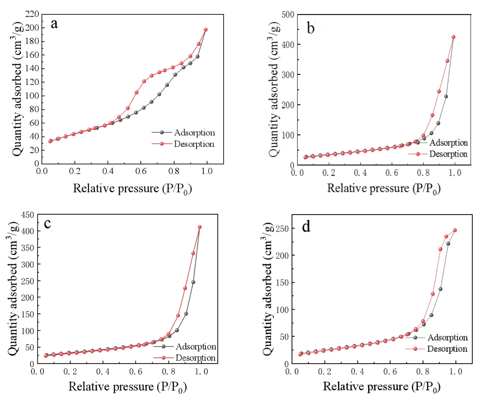
Fig.3.(Color online) Absorption–desorption isotherm of the TiO2 (a) NTs,(b) NRs,(c) NWs,and (d) NPs.
To investigate the effect of TiO2morphological changes on dye 719 adsorption capacity,Fig.4 demonstrates the Ultraviolet (UV)–visible absorption spectra of dye N719 made from the flexible TiO2photoanode with different morphologies,which shows three absorption peaks at 308,373,and 503 nm for the dye N719.The TiO2NTs photoanode has the strongest signals,and the orders of the signal strength for the nano TiO2are NTs﹥NRs﹥NWs﹥NPs.This result indicates that the TiO2NTs photoanode loads more dyes according to the Lambert–Beer’s law,which means more incident light harvested and the larger photocurrent occurs[31].

Fig.4.(Color online) The UV-visible absorption spectra of dye desorbed from TiO2 films of NPs,NWs,NRs,and NTs.
Figs.5(a) and 5(b) are the HRTEM images of TiO2NTs with approximate lattice spacing of 2.44-3.71 nms (Fig.5(c))and mooth surface,which indicates that most of the P25 particles have been changed into TiO2NTs.The length of the TiO2NTs is about 100 nm and the diameter is around 15 nm.Fig.5(d) shows the SAED image of TiO2NTs.It can be seen that the TiO2NTs are multicrystal structure,and belongs to the (101),(004),and (200) crystal faces for anatase phase.

Fig.5.(a-c) HRTEM images and (d) SAED pattern of the TiO2 NTs.
Figs.6(a) and 6(b) show the SEM images of the porous PEDOT CE.The PEDOT film with uniform network structure is in favour of improvingI-/I3-electrolyte’ penetration and enhancing the contact area between CE and electrolyte.Fig.6(c) shows the CVs of the Pt and PEDOT CEs at the scan rate of 50 mV∙s-1.The PEDOT CE have a higher current density (Ipc) absolute value and smaller overpotential (Vpc) than that of the Pt CE.Both the max anode peak current density(Ipa) andIpcare almost unchanged in Fig.6(d) which indicates a great electrochemical stability for the PEDOT CE[32].This phenomenon signifies that the PEDOT CE possesses the Pt-like electrocatalytic ability forI3-reduction due to the low overpotential loss and highly conductive for the PEDOT CE[33].

Fig.6.(Color online) (a,b) SEM images of the porous PEDOT CE;(c) the CVs for the Pt and PEDOT CEs;and (d) the 50 successive CV cycles of the PEDOT CE at the scan rate of 50 mV∙s-1.
Fig.7 shows the photovoltaic properties of various FDSSCs under the rear illumination of 100 mW∙cm-2and the detailed parameters are summarized in Table 2.The power conversion efficiencies (PCEs) of the FDSSCs assembled with TiO2NTs and the Pt and PEDOT CEs in Fig.7(a) achieves 5.06% and 7.83%,respectively,which is remarkably higher for the latter than that of the former.This is mainly because the much higher transmittance for the PEDOT CE than that of the Pt CE,and the decrease in incident light intensity via the reflection of Pt CE[34,35].Fig.7(b) shows theJ-Vcurves of the FDSSCs based on the PEDOT CE and the TiO2NPs,NWs,NRs,and NTs photoanodes under the rear irradiation.The FDSSCs with the TiO2NRs and NTs photoanodes show as high as PCEs of 7.65% and 7.83%,higher than that of the TiO2NPs(6.96%) and NWs (7.36%) photoanodes.The distinction in performance of the cells possibly is derived from the differences in electronic transmission of nano TiO2.The TiO2NRs and NTs with directional structure are more conducive to electronic transmission than that of the TiO2NPs and NWs.Simultaneously,the reduction of dye loading capacity on TiO2photoanode also plays a certain role for the TiO2NPs and NWs.

Table 2.The photoelectric properties of the FDSSCs with various CEs and photoanodes.
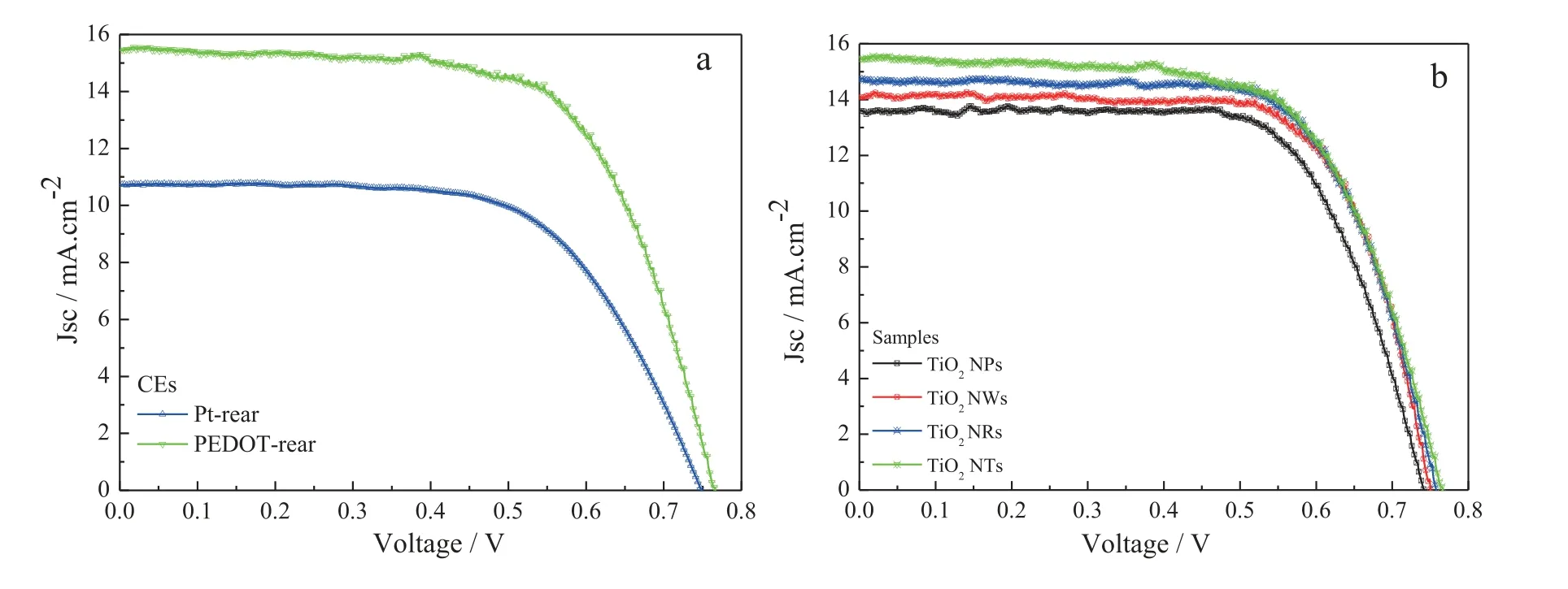
Fig.7.(Color online) J-V characteristics of the FDSSCs fabricated with different photoanodes under the standard illumination.
Fig.8 presents the Nyqyist plots of the devices with TiO2NPs,NWs,NRs,and NTs photoanodes and PEDCT CE,in which the performance of devices is directly related to the charge transfer resistance (Rct1andRct2)[36].Because of TiO2directional structure could enhance the electron collection efficiency in devices,therefore,the cell based on TiO2NTs photoanode shows the lowest valuesRct1of 2.80 Ω∙cm2andRct2of 6.61 Ω∙cm2,and the other three devices with the TiO2NPs,NWs,and NRs photoanodes display theRct1of 5.06,4.17,and 3.59 Ω∙cm2,and corresponding to theRct2of 10.09,9.56,and 8.31 Ω∙cm2.The former shows the smallestRct1andRct2compared to the latter cells.This implies that the TiO2NRs and NTs with directional structure for the devices are better for electronic transmission than that of the TiO2NPs and NWs,resulting in a higher fill factor (FF) and short-circuit current density.This is in consistent with the results of UV-visible andJ-Vphotovoltaic performance.

Fig.8.(Color online) EIS spectra of FDSSCs with the various photoanodes and the relevant equivalent circuit model.
Fig.9 shows the architecture of a FDSSC with TiO2NTs photoanode irradiated from the rear.The function of the TiO2blacking layer can reduce the backwash of elections from Ti foil substrate to the electrolyte,thereby enhancing the longterm stability of FDSSC.The TiO2NTs provide an unobstructed path for electron transfer,which helps improve the efficiency of charge transfer and electron collection.Moreover,the light emitted from the back can penetrate and be absorbed by the N719 dye very well due to the good transparency of the PEDOT CE,producing more photogenerated charge carriers in FDSSC,and resulting greatly enhanced the short-circuit current density and a superior PCE of 7.83%.

Fig.9.(Color online) Schematic for a FDSSC based on TiO2 NTs photoanode irradiated from the rear.
4.Conclusions
An efficient FDSSCs assembled with net-work structure’PEDOT CE and TiO2NPs,NWs,NRs,and NTs photoanodes achieved power conversion efficiency of 6.96%,7.36%,7.65%,and 7.83% under rear illumination of 100 mW∙cm-2.The morphology of TiO2has a significant influence on the photovoltaic performances of FDSSCs.These four FDSSCs with various TiO2photoanodes morphology possess good fill factor and open circuit voltage,especially for the FDSSCs with TiO2NRs and NTs photoanodes,which generate higher short circuit current density.This is responsible for their oriented structure of NRs and NTs,which are more beneficial to electron and hole transmission in the semiconductor compared to the TiO2NPs and NWs photoanodes.This strategy can be further improved by designing a better light-splitting device with vertical incidence and applied other devices with transparent CEs.
Acknowledgements
The authors are very grateful to the joint support by NSFC (No.61704047).This work is also supported by Science and Technology Development Project of Henan Province(Nos.212102210126 and 202300410057).
杂志排行

Journal of Semiconductors的其它文章
- An advanced theoretical approach to study super-multiperiod superlattices: theory vs experiments
- Two-step growth of β-Ga2O3on c-plane sapphire using MOCVD forsolar-blind photodetector
- Controllable step-flow growth of GaN on patterned freestanding substrate
- Controllable thermal rectification design for buildings based on phase change composites
- Enhanced thermal emission from metal-free,fully epitaxial structures with epsilon-near-zero InAs layers
- Research progress of alkaline earth metal iron-based oxides as anodes for lithium-ion batteries