甲醇为氢源的连续化催化转移加氢合成芳胺
2024-02-23洪学立洪云阳宋素红王千禧严新焕
洪学立 洪云阳 宋素红 王千禧 严新焕
(浙江工业大学绿色化学合成技术国家重点实验室培育基地,杭州 310014)
NH2moieties are present in a wide variety of pharmaceutical molecules, dyes, agrochemicals, and bulk chemicals[1].Especially aromatic amines play a privileged role in medicinal chemistry[2-3].There are many methods to synthesize aromatic amines[4-8].The typical process for synthesizing aromatic amines is to use hydrogen as the hydrogen source and obtain it by catalytic hydrogenation of noble metal catalysts such as Pd[9-11].However, those methods involve the direct use of gaseous H2, which adds additional difficulty in handling due to safety reasons, particularly in large-scale commercial applications[12].As people′s environmental protection and security requirements continue to increase, it is still necessary to develop simple, efficient,and green synthesis methods.
Catalytic transfer hydrogenation with anin-situhydrogen donor has received a great deal of attention from both academia and industry as an alternative to the traditional high-pressure hydrogen process, owing to its better efficiency,atom economy,and sustainability features[13-15].Based on this, some new synthetic methods have been developed.In this regard, methanol[16-19]is a very attractive hydrogen donor.Methanol can be produced from fossil resources and renewable resources[20].Methanol has been referred to as “the safest source of hydrogen[19]”.But compared to the commonly used hydrogen transfer reagent, isopropanol[21-24],the dehydrogenation of methanol requires higher energy[25].There have been some reports on the synthesis of amines by hydrogen transfer reaction of methanol.Li′s group[25]has explored the hydrogen transfer reaction of nitrobenzene with Pd-Ba/Al2O3and Pd-Fe/Al2O3, and the yield could reach 51.45%.However, the substrate is limited to the nitrobenzene.Zhu and coworkers[26]reported that X zeolites exhibited higher catalytic performance for the transfer hydrogenation of 2-nitrotoluene with methanol.Transfer hydrogenation achieved the highest conversion of 2 - nitrotoluene(76.70%) over NaX and the highest yield of main product 2-methylaniline (42.53%) over KX.Ray and coworkers[27]reported a series of aromatic amines were obtained within 24 h at 100-120 ℃in the presence of KOtBu using Pd/C as a catalyst.However, catalytic transfer hydrogenation of nitroarenes using methanol is still underdeveloped.Developing a catalytic system that efficiently utilizes methanol for hydrogen transfer is still necessary.
Earlier, we reported the synthesis of quinoline compounds from nitroarenes and ethanol/water.Interestingly, the formation of amines intermediate compounds was found in the course[28], which inspires us to envisage the selective hydrogenation of nitroarenes to amines via hydrogen transfer reactions.Unlike the previous work, we chose methanol as the hydrogen source and solvent, focusing on preparing amines from nitroaromatics.Thus, an effective and mild synthesis method of amines from the nitroarenes was developed by us using Ru-Fe/γ-Al2O3as catalysts and methanol/water as a hydrogen source and solvent under mild conditions in a fixed-bed flow reactor.This present protocol exhibited excellent yield and selectivity for unsaturated group-substituted nitroarenes such as aldehyde, carbonyl, or alkynyl-substituted starting nitro compounds.
1 Experimental
1.1 Materials
Ethanol (AR), acetone (AR), methanol (AR),isopropanol (AR), and Fe(NO3)3·9H2O (AR) were purchased from Sinopharm Chemical Reagent Co., Ltd.m-dinitrobenzene (m-DNB, AR),o-chloronitrobenzene(AR),m-chloronitrobenzene (AR),p- chloronitrobenzene (AR), 3,4-dichloronitrobenzene (AR),o-bromonitrobenzene (AR),p-bromonitrobenzene (AR),p-nitrobenzaldehyde(AR),o-nitrobenzaldehyde(AR),m-nitrobenzaldehyde (AR),o-nitrophenol (AR),p-nitrophenol(AR),o-nitrobenzonitrile (AR),p-nitroacetophenone(AR),p-nitrostyrene (AR) were purchased from Shanghai Macklin Biochemical Co., Ltd.RuCl3·3H2O(CP) was purchased from Sino-Platinum Metals Co.,Ltd.γ-Al2O3(1-2 mm) was purchased from Henan Zhongbang Environmental Protection Technology Co.,Ltd.The water used for all the experiments was deionized water.
1.2 Catalyst preparation
Ru-Fe/γ-Al2O3was prepared by a sequential impregnation method.Typically,the metered Fe(NO3)3·9H2O aqueous solution was added to a beaker containing a certain amount ofγ-Al2O3, and the mixture was kept at 70 ℃and stirred to dryness.The obtained sample was calcined in N2at 260 ℃for 2 h and reduced in H2at 260 ℃for 2 h.Then, the reduced catalyst particles were transferred to the stoichiometric RuCl3·3H2O aqueous solution in the same operation and stirred at 70 ℃to dry.The obtained sample was calcined again in N2at 260 ℃for 2 h and reduced in H2at 260 ℃for 2 h to get a Ru-Fe/γ-Al2O3catalyst.Catalysts with different Ru/Fe mass ratios (including Ru and Fe) were
prepared under the same operating conditions.The theoretical loading of the catalysts used for characterization was expressed by mass fraction.For example,the theoretical loading (mass fraction) of Ru and Fe was all 5%, which was referred to as 5% Ru-5% Fe/γ-Al2O3.The theoretical loading (mass fraction) of single Ru was 5%, which was referred to as 5% Ru/γ-Al2O3.The theoretical loading (mass fraction) of single Fe was 5%,which was referred to as 5% Fe/γ-Al2O3.
1.3 Characterization of the catalysts
Metal element content in the catalyst was determined by inductively coupled plasma-mass spectrometry(ICP-MS)using Agilent 7500 CE.
The TEM was performed using JEOL JEM -1200EX with an operating voltage of 200 kV.The elements contained in the catalyst were analyzed using an energy spectrometer (EDS).Before analysis, the catalyst particles to be tested were ground to powder form using a mortar and pestle and dispersed with ethanol; a small amount of sample was taken and dropped onto a microgrid Cu grid, dried with an infrared lamp, and sent to the instrument for observation and analysis.
X-ray diffraction (XRD) patterns were performed using a Dutch PANalytical X-ray diffractometer with CuKαradiation (λ=0.154 1 nm).The working voltage was 40 kV, the working current was 40 mA, and the pattern was collected in a step of 0.026 2° in the range of 2θfrom 10°to 80°.
The hydrogen temperature-programmed reduction(H2-TPR) experiment was conducted using a fully automated chemisorption instrument, Autochem2910, from Mac, USA.At first, the pellet samples were pretreated at 260 ℃for 1 h under argon, cooled to 50 ℃and then the gas was switched to a 5% H2-Ar mixture and ramped up to 800 ℃at a rate of 10 ℃·min-1.A thermal conductivity detector was used to record the sample′s signal in the heating range.
1.4 Experimental procedure
All catalytic tests were carried out in a laboratorymade fixed-bed flow reactor.The fixed bed reactor was a stainless-steel tube with an inner diameter of 6 mm and a length of 60 cm.The quartz beads were filled at both ends to fix the catalyst in the middle of the reaction tube.An outer heating sleeve heated the reaction tube, and the reaction temperature was measured by a thermocouple placed between the outer heating sleeve and the reaction tube.The temperature controller connected to the outer heating sleeve to accurately control the temperature rise.A back pressure regulator controlled the pressure of the reaction system and a liquid phase pump was used to transport the solution to maintain the pressure continuously.In the typical catalytic transfer hydrogenation process,5 g Ru-Fe/γ-Al2O3was fixed in the middle of the reaction tube, and a certain concentration ofm-DNB solution was transported to the reaction tube through a liquid phase pump at a flow rate of 1 mL·min-1, When the solution flew out of the reaction tube,the pressure of the back pressure regulator was adjusted to 3 MPa.After the pressure was stabilized, the temperature controller was adjusted to the temperature required for the reaction.After the system was stable, samples were collected after regular intervals(30 min)and used Shimadzu gas chromatography(GC-2014,FID,AT.OV-1701)for real-time analysis.The identification of the compounds was performed by comparison of the retention times with pure standards.The scheme of the reaction equipment was shown in Fig.1.
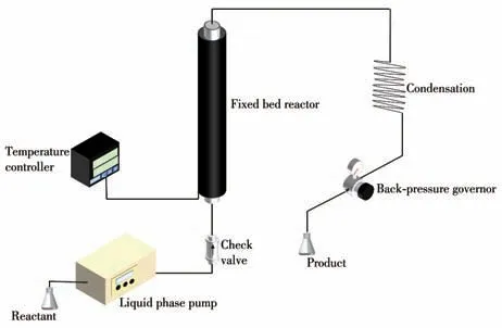
Fig.1 Scheme of the reaction equipment
2 Results and discussion
2.1 Characterization of the catalysts
The contents of Ru and Fe in the catalyst were determined by ICP-MS.The results are shown in Table 1.The actual loadings (mass fraction) of Ru and Fe were 4.85% and 4.81%, respectively, which were close to the theoretical values (5%Ru-5%Fe/γ-Al2O3).The loading decreased slightly after the reaction and the loss was less, which may be caused by trace leaching during the reaction.

Table 1 Loading of Ru-Fe catalysts
TEM results were shown in Fig.2.In Fig.2a, 2c,and 2d, the nanoparticles loaded onγ-Al2O3had no obvious agglomeration and were well dispersed.Fig.2b shows the particle size distribution of the catalyst.The particle size of nanoparticles was relatively small, the particle size distribution was 1.31-4.01 nm, and the average particle size was about 2.95 nm.Fig.2e, 2f were TEM images of the catalyst after the reaction.Thesize of the reacted catalyst nanoparticles remained small and uniformly dispersed with no obvious agglomeration,indicating good stability of the catalyst.

Fig.2 TEM images of the fresh(a,c,d)and the recovered(e,f)5%Ru-5%Fe/γ-Al2O3 catalyst;Ru-Fe nanoparticles distribution of the 5%Ru-5%Fe/γ-Al2O3 catalyst(b)
The results of the EDS analysis are shown in Fig.3.Ru and Fe elements are evenly distributed on the surface of the carrier without obvious agglomeration, which further proves that the catalyst had good dispersion and uniform particle size.It was also observed that the distributions of Ru and Fe do not completely overlap, which, in combination with other characterization tools,suggested that Ru and Fe are not present in an alloy structure, but rather in separate nanoparticle structures.

Fig.3 EDS element mapping diagram of the(a)5%Ru-5%Fe/γ-Al2O3,(b)Ru,and(c)Fe
The results of the XRD analysis are shown in Fig.4.Compared with the standard PDF No.00-001-1303,there were three diffraction peaks at 45.8°,60.9°,and 66.8°, which corresponded to the (111), (210), and(211) crystal planes ofγ-Al2O3carrier, respectively.Compared with the standard PDF No.00-026-1136,the diffraction peaks were observed at 31.2° and 36.8°,which belonged to the (220) and (311) crystal planes of Fe3O4, indicating that Fe element existed in the form of Fe3O4in the catalyst.Martínez et al.suggested that the Fen+site can inhibit the formation of intermediate hydroxylamine in nitroaromatic hydrogenation reactions and improve the selectivity of the reaction[29], and Li et al.concluded that Fe3O4promoted the formation of Ru0species[30].In addition, no obvious Ru diffraction peak was found in the spectrum, which was attributed to the good dispersion and small particle size of Ru nanoparticles, by the granularity statistics of the TEM(2.95 nm).

Fig.4 XRD pattern of the catalyst
The results of H2-TPR analysis of three typical catalysts are shown in Fig.5.Curve A was the H2-TPR information of the 5%Fe/γ-Al2O3catalyst.The reduction peak at about 350 ℃was attributed to the reduction peak from Fe2O3to Fe3O4.The 5%Ru/γ-Al2O3catalyst in curve B showed a reduction peak near 190 ℃,which may be attributed to the reduction of the RuO2substance with weak interaction with the support.A weak reduction peak near 450 ℃may correspond to the reduction formed by the strong interaction between the RuO2substance and the support.Curve C was the H2-TPR information of the 5%Ru-5%Fe/γ-Al2O3catalyst.The reduction peaks appeared at 130 and 420 ℃,respectively.There may be electron transfer between Ru and Fe species, which changed the interaction between each other and theγ-Al2O3support.This interaction made the reduction peak of Ru species move to low temperatures and promotes the reduction of Ru,which also confirmed the study of Li et al.that Fe3O4promoted the formation of Ru0species[30].
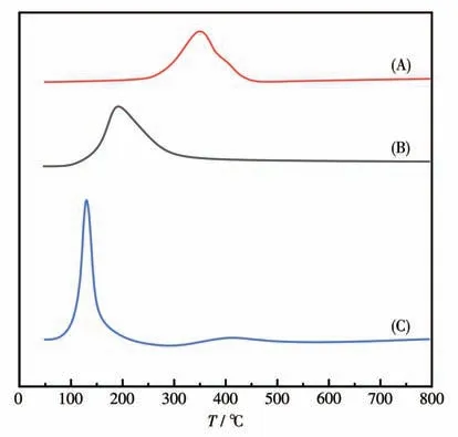
Fig.5 H2-TPR spectra of the catalysts(A)5%Fe/γ-Al2O3,(B)5%Ru/γ-Al2O3,and(C)5%Ru-5%Fe/γ-Al2O3
2.2 Catalytic activity of the catalysts
To evaluate the performance of the catalysts for the hydrogen transfer reaction, we first explored the transfer hydrogenation ofm-DNB.Table 2 shows the effect of different solvents on the reaction.The results showed that methanol was the best solvent and hydrogen donor for this hydrogen transfer system.From the entries 5 and 9 in Table 2, methanol/water displayed better catalytic efficiency than isopropanol/water, a commonly used hydrogen donor in hydrogen transfer reactions.Fig.6A shows the effect of different methanolto-water ratios on the reaction.The reaction was more favorable when the methanol/water volume ratio was 8∶2.We found that the conversion rate increased significantly when a small amount of water was added to the system.With the increase in water ratio,the conversion remained almost unchanged, and the selectivity decreased slightly but remained at a high level.This was different from the research by Cecilia and coworkers[22].According to the density functional theory calculation by Wang et al.[31], nitrobenzene surpassed aniline in competing for surface active sites with the addition of water.This may also apply to our system.The difference between the two was conducive to the adsorption ofm-DNB and desorption ofm-nitroaniline(m-NAN), which increased the adsorption concentration ofm-DNB, reduced the adsorption concentration ofm-NAN, and improved the activity and selectivity.Akula et al.believed that the spillover of H on the catalyst surface from H2O further enhances the Ru hydrogenation capacity and improves the selectivity[32].Therefore, the solvent for the reaction system was chosen as methanol/water, and the ratio of methanol/water was 8∶2.

Table 2 Catalytic properties of the catalysts with different mass ratios of Ru/Fe and in different solventsa

Fig.6 Catalytic properties of hydrogenation of m-DNB
Table 2 also shows the catalytic performance of the catalysts with different Ru-Fe mass ratios under the same conditions.The transfer hydrogenation activity of monometallic Fe catalyst was low.The transfer hydrogenation activity of a single metal Fe catalyst was much lower than that of a single metal Ru catalyst,indicating that Ru had good catalytic activity for the reaction system, while Fe alone showed relative inertia.The cata-lytic selectivity of 5% Ru-5% Fe/γ-Al2O3bimetallic catalysts form-NAN was higher than that of single 5% Ru/γ-Al2O3or 5% Fe/γ-Al2O3single metal catalysts.More interestingly,the 5% Ru-5% Fe/γ-Al2O3bimetallic catalyst further improved the transfer hydrogenation activity ofm-MAN compared with the single 5% Ru/γ-Al2O3catalyst.When the content of Fe was too high,the yield ofm-NAN decreased.This may be because the active center Ru determines the adsorption and desorption ability of the catalyst to the reactants.After adding a small amount of Fe species, the synergistic effect of Ru and Fe metals improved the transfer hydrogenation activity[31].Combined with TEM, XRD, and other characterizations, the nanoparticles on the catalyst′s surface had small particle size and good dispersion.
As shown in entry 7 of Table 2, we chosen a suitable reaction condition, using hydrogen as the hydrogen source,and using 5% Ru-5% Fe/γ-Al2O3to hydrogenatem-DNB through a traditional autoclave.It was found that the selectivity ofm-NAN (60.1%) was not high when the conversion rate (90.8%) was not high,which was much lower than the selectivity ofm-NAN(99.4%) in our continuous flow hydrogenation system using methanol as the hydrogen source.At the same time, compared with the traditional high-pressure reactor,the continuous flow production mode was more efficient.Continuous flow hydrogen transfer hydrogenation with methanol as the hydrogen source was advantageous.
We have also explored the reaction′s temperature,pressure, flow rate, and stability.As shown in Fig.6B,as expected, the conversion continued to increase until 100% with the temperature increased.However, the selectivity began to decrease when the temperature rose to 140 ℃.As shown in Fig.6C, under different pressures,the conversion and selectivity of the reaction hardly changed, indicating that the pressures had nothing to do with the reaction.However, to maintain the entire system′s stability and keep it in a liquid phase,the final pressure was 3 MPa.As for the flow rate,when the flow rate was too fast, the contact time between the substrate and the catalysts became shorter, and the reaction was not sufficient.When the flow rate was too slow, the contact time between the substrate and the catalysts became longer,and the selectivity of the reaction decreased.So, the appropriate flow rate was 1 mL·min-1.The results were not listed in the paper.The stability of the catalyst was evaluated for its recyclability, as shown in Fig.6D.To investigate the stability of 5% Ru-5% Fe/γ-Al2O3for this hydrogen transfer reaction, the experiment was carried out for 24 h.The conversion ofm-DNB and the selectivity ofm-NAN did not change significantly, indicating that the catalyst had high stability during the whole hydrogen transfer process.
As shown in Fig.7,to compare with the stability of 5% Ru-5% Fe/γ-Al2O3for the hydrogen transfer reaction, the stability of 5% Ru/γ-Al2O3for the reaction was also studied, and the experiment was also carried out for 24 h.The conversion ofm-DNB was significantly reduced, indicating that the addition of Fe could improve the stability of the catalyst.Good stability was essential in continuous flow reactions.

Fig.7 Catalytic properties of hydrogenation of m-DNB
2.3 Substrate expansion
Under the optimized conditions, a variety of nitroarenes can be reduced with methanol to the corresponding amines in high conversion and selectivity(Table 3).There were also reducible aldehyde groups and cyano groups in nitro benzaldehyde and nitro benzonitrile, which were not reduced to the corresponding alcohols and amines, which were usually difficult to achieve in H2hydrogenation reactions.Similarly, the selectivity of corresponding halogenated aromatic amines was also good for halogenated nitroaromatics.The substituents on the aromatic ring had an insignificant effect on the reaction and can tolerate various substituents,including aldehyde,cyano,nitro,halides,carbonyls, and hydroxyl, and the conversion did not vary considerably with the position of substitution, e.g., ortho and para.

Table 3 Transfer hydrogenation of nitroarenes under optimized conditionsa
3 Conclusions
In conclusion, as far as we know, we have pioneered the development of heterogeneous Ru-Fe catalysts for the continuous conversion of nitroaromatics to corresponding amines using methanol as a solvent and hydrogen source.The system also produces the corresponding aromatic amines with better selectivity than the conventional hydrogen hydrogenation reaction.The catalyst synthesis path is convenient, the stability is good,and it may have wide applicability.
