Ballistic response of skin simulant against fragment simulating projectiles
2023-12-27PunitKumrPndeyAtulHrmukhKhnIqlGnpule
Punit Kumr Pndey ,Atul Hrmukh ,M.K.Khn ,M.A.Iql ,S.G.Gnpule ,c,*
a Department of Mechanical and Industrial Engineering, Indian Institute of Technology Roorkee, 247667, India
b Department of Civil Engineering, Indian Institute of Technology Roorkee, 247667, India
c Department of Design, Indian Institute of Technology Roorkee, 247667, India
Keywords:Skin simulant Fragment Impact Ballistic limit velocity Energy density Failure
ABSTRACT The response of biological phantoms against high velocity impact is actively sought for applications in defense,space,soft robotics and sensing.Towards this end,we study the ballistic response of silicone based skin simulant against fragment impact.Using a pneumatic gas gun setup,six chisel-nosed and three regular shaped (sphere,cylinder,and cube) fragments were impacted on the skin simulant.The resulting skin simulant response was studied in terms of ballistic limit velocities,energy densities,failure pattern,and the mechanics of interaction.The results indicate that the shape of the fragment affects the ballistic limit velocities.The ballistic limit velocities,energy densities of the chisel-nosed fragment simulating projectiles were relatively insensitive to the size (mass),except for the smallest (0.16 g) and largest (2.79 g) chisel-nosed fragment.For the same size (1 g),ballistic limit velocities and failure are dependent on the shape of the fragment.The skin simulant failed by combined plugging and elastic hole enlargement.Failure in the spherical fragment was dominated by the elastic hole enlargement,whereas plugging failure was dominant in all other fragments.The spherical,cylindrical,and chisel-nosed fragments created circular cavities,and the cubical fragment created a square cavity.In the case of the spherical fragment,slipping of the fragment within the skin simulant was seen.Cubical fragments created lateral cracks emanating from the corners of the square cavity.Interestingly,for all the fragments,the maximum deformation corresponding to the perforation was lower than the non-perforation indicating rate dependent,stress driven failure.The maximum deformation was also dependent on the shape of the fragment.Overall,these results provide unique insights into the mechanical response of a soft simulant against ballistic impact.Results have utility in the calibration and validation of computational models,design of personal protective equipment,and antipersonnel systems.
1.Introduction
Skin is a vital body organ and the first order of defense against any external stimuli [1-3].The response of skin against ballistic impact is critical from both protection and lethality points of view[4-7].This capability is especially important in tactical warfare[8,9] involving guided missiles,antipersonnel warheads,improvised explosive devices,rocket-propelled grenades,and explosives mines.These antipersonnel systems carry ammunition containing irregular shaped fragments that are smaller than conventional ammunition,such as bullets [7].Fragments are typically designed for wounding and incapacitation.Perforation of the fragment into the skin is deemed sufficient for wounding and incapacitation and sought-after outcome from fragment projectiles and the aforementioned ammunition.Thus,the ability to perforate a skin or skin simulant is one of the critical design parameters [6,10,11] in developing modern ammunition containing fragments [7,12-14].
Classical literature has mainly focused on studying the response of biological phantoms against bullets(e.g.Refs.[15-19],).Recently,some efforts have been made to study the response of skin or skin simulants against smaller fragments [5,20-24],especially to determine ballistic limit velocity.However,data in this regard is highly scattered due to the lack of standardization (e.g.,complete organ vs.isolated tissue,specimen condition: fresh,refrigerated,different fragment shapes and sizes,reported threshold vs.V50ballistic limit velocities,differences in experimental methodology).As a result,for a given size,differences on the order of ±200% in ballistic limit velocity have been observed across various investigations (e.g.,see Ref.[5] and references therein).Breeze et al.[5] collected extensive data from the literature and compiled the ballistic limit velocities of the skin against fragment impact.They plotted ballistic limit velocities of the skin against the sectional density (mass per presented c/s area) of the fragment.From this data,Breeze et al.[5] derived a best fit curve for the ballistic response of the skin as a function of sectional density.Numerous empirical equations [25-29],based on experimental data,have been proposed in the literature to determine the ballistic limit velocity of a skin.Further,most of the studies are based on regular shaped fragments with limited data on NATO defined chisel-nosed,cylindrical fragment simulating projectiles (FSP) [30].
Faithful testing of skin in a controlled environment poses significant challenges.Skin simulants are generally favoured for controlled laboratory testing [23].The ability to launch smaller fragments at desired velocities within a narrow range is not easily achieved.This has resulted in a wide range of fragment impact velocities [20].Measurements using the complete organ in obtaining the ballistic limit of a skin are affected by the backing material [5,20,22].
The response of soft materials such as skin simulants[31]under impact is also sought for applications in space(e.g.,Ref.[32]),sports and automotive injuries (e.g.,Refs.[33,34]),in the development of next-generation of soft sensing technologies (e.g.,Ref.[35]),and soft robotics (e.g.,Refs.[36-38]).The mechanics of interaction of smaller fragments with thin,soft targets is not known.The data in the literature is mainly available for projectiles of larger masses and in thicker targets [15-19],wherein the mechanics of interaction can potentially be different.Thus,there is a need to understand the response of isolated skin or skin simulant against fragment impact.Such data is critical for the design of modern ammunition,especially in regard to wounding potential,and also of general interest for applications listed above.
Towards this end,we study the response of skin simulant against chisel-nosed cylindrical FSPs and regular (sphere,cylinder,cube) shaped fragments using experiments.The ballistic limit for six different chisel-nosed,cylindrical FSPs and three regular shaped fragments have been determined experimentally.In order to avoid confusion with the regular shaped cylindrical fragment,we will refer to chisel-nosed,cylindrical FSP as chisel-nosed FSP in the remainder of the manuscript.We also study the mechanics of interaction of the fragments with skin simulant.The manuscript is organized as follows.In the method section,we describe the details of the experiment,including pneumatic gas gun setup,fragments,skin simulant,and ballistic testing.In the results section,we present threshold (Vth) and ballistic limit (V50) velocities,energy densities,failure pattern,and skin simulant deformation.The next section discusses the results with respect to the existing literature in the context of ballistic limit velocities,failure mechanisms,rate dependent behavior,and broader implications of this work.The key findings are summarized in the conclusion section.
2.Methods
2.1.Pneumatic gas gun setup and fragment simulating projectiles
The response of skin simulant against FSPs has been studied using a pneumatic gas gun setup (Fig.1).Six different sizes of chisel-nosed FSPs (Fig.2(a)) ranging from 0.16 to 2.79 g were manufactured according to NATO STANAG 2920 [30].In addition,spherical,cylindrical,and cubical (Fig.2(b)) fragments of size(mass)1 g were prepared.All fragments were fabricated using mild steel.Fragments were launched using a pneumatic gas gun setup.The pneumatic gas gun setup (Fig.1) consisted of a compressor,pressure vessel,actuated ball valve,pressure gauge,and barrel.A barrel of 25 mm internal diameter and 5 m length was used.The fragment was launched by triggering the actuated ball valve at the predetermined set pressure of the pressure vessel.Different fragment launch velocities in the range of 20-300 m/s can be achieved by adjusting the pressure in the pressure vessel and barrel length.For a given barrel pressure and barrel length,fragment launch velocities can be controlled with a precision of ±5 m/s.Since the diameter of fragments was different from that of the barrel,Nylon sabots (Fig.2(c)) were used to hold the fragment within a barrel.Precisely manufactured split sabots were made up of two symmetrical parts,which opened due to the air drag after getting released from the barrel.The fragment moved faster than the sabot upon opening and left the sabot behind due to the sabot’s heavier weight and higher frontal drag.We ensured that fragments came out straight and did not tumble before impacting.The shots with the tilt were not included in the analysis.Further,fragments primarily impacted at the middle of the square skin simulant target.

Fig.1.Experimental setup: (a) Photograph of a complete experimental setup;(b) Zoomed-in view of fragment launching assembly;(c) Schematic of fragment-target setup;(d) A top view schematic illustration of a complete experimental setup.
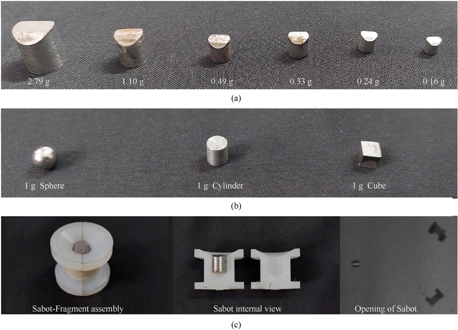
Fig.2.Photographs of fragments and sabot:(a)Chisel-nosed fragment simulating projectiles prepared in accordance with NATO STANAG 2920;(b) Regular shaped fragments;(c)Sabot-fragment assembly and sabot opening in action.
2.2.Skin simulant
A two-part silicone material (Smooth-On,Inc.,Macungie,PA)with a shore hardness of 30A was used as a skin simulant.This material gives a stress-strain response similar to human skin[38-40].The mechanical properties and stress-strain curve[39,41]of the skin simulant used in this work are given in Table 1 and Fig.3,respectively.The skin simulant (i.e.,silicone rubber) used in this work has a shore hardness of 30A.For this material,the mechanical properties and stress-strain curve [39,41] are only available at the quasi-static strain rate.However,the dynamic properties of a similar rubber with a shore hardness of 45A are available in the literature [42,43].The mechanical properties and stress-strain curves [42,43] for the rubber with a shore hardness of 45A are provided in the supplementary material (Table S1,Fig.S1) for completeness.

Table 1 Mechanical properties(quasistatic) of the silicone rubber [39,41] used in this work.
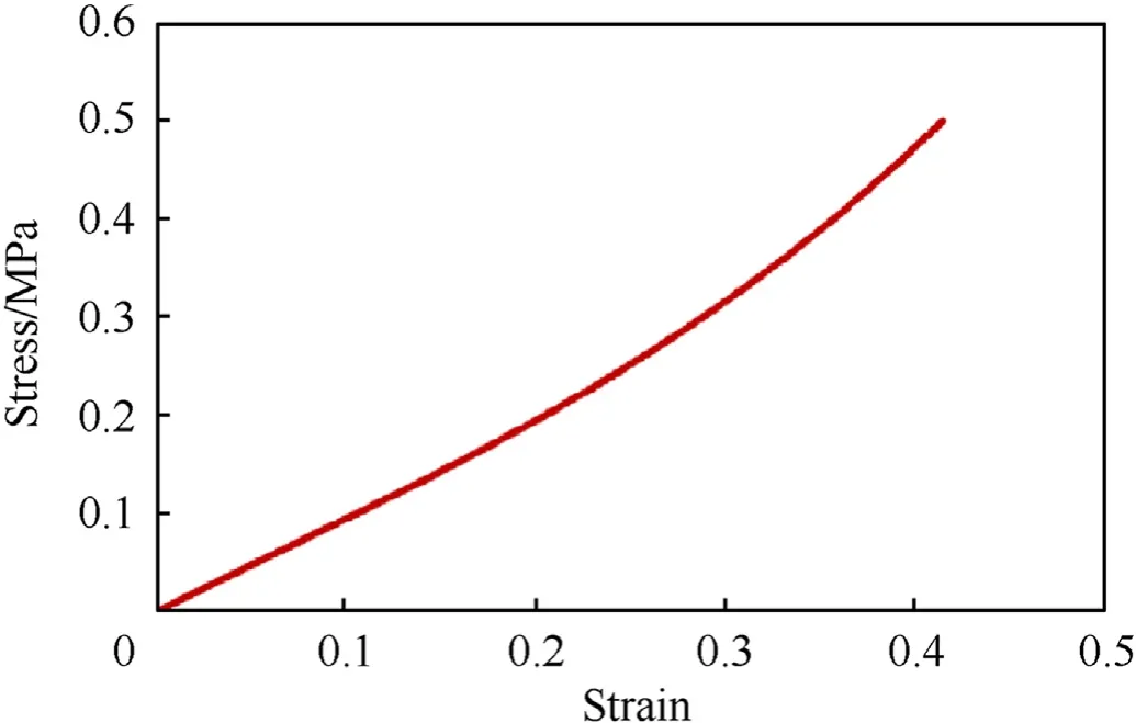
Fig.3.Stress-strain (quasistatic) response of silicone rubber [39] used in this work.
Skin simulant was prepared in the form of the 100 mm×100 mm square cross-section and thickness of 3 mm (Fig.4(a)).The thickness of 3 mm was selected based on the average skin thickness values reported in the literature [25,31,44].Skin simulant was prepared by mixing two parts (i.e.,Part A and Part B) of silicone material in the ratio of 1:1 by weight.During preparation,the mixture was stirred thoroughly to make it homogeneous.The mixture was poured into a 3D printed PLA mold and cured at room temperature for 16 h.

Fig.4.(a) Photograph of a skin simulant prepared in the form of 100 mm×100 mm square c/s and 3 mm thickness;(b) Mounting of skin simulant on a test fixture.
2.3.Ballistic testing of skin simulant
For ballistic testing,skin simulant was fixed in a target holding frame containing a slot of 100 mm×100 mm(Fig.4(b)).All the edges were fully constrained by clamping tightly using metal plates and fasteners.The samples were kept at a distance of 1 m from the open end of the barrel.The impact event was captured using two highspeed cameras(Phantom v411,Vision Research,Inc.,Wayne,NJ).To measure impact velocities,the first camera(camera-1)was installed normal to the fragment’s path(Fig.1(d)).The camera was set up such that its plane of focus coincided with the travel plane of the fragment.To capture the overall mechanical response of the skin simulant to the impact,the second camera (camera-2) was installed at certain angle to the target(Fig.1(d))such that frontal face is visible.The second camera is mainly used to see the front face of the target to verify that only FSPs and not sabots are hitting the target.
The frame rate was set from 10,000 to 16,000 frames per second based on the desired resolution.The impact and residual velocities were estimated from high-speed images.A distance traveled by the fragment was calculated from pixel to millimeter calibration for the plane of the fragment’s travel path.In each frame,the pixel location was obtained at the center of the fragment.The difference in pixel coordinates in consecutive frames gave the traveled distance,after multiplying by pre-computed calibration scale (i.e.,pixel to millimeter scale).The velocity of a fragment was calculated by dividing this distance by the time interval between two frames,which is constant.To ensure the accuracy of estimates,the velocities were calculated over multiple successive frames(just before the impact),and these velocities were averaged.Typically,the velocities remained fairly constant over multiple successive frames.
The perforated fragments were arrested using a catcher box filled with cotton.A number of experiments for each fragment size were performed to estimate the ballistic limit velocities.A given sample was impacted only once to exclude any pre-condition effect irrespective of perforation or non-perforation.To study failure pattern,samples were recovered post-impact for imaging and visual inspection.
2.4.Estimation of ballistic limit velocities
The threshold velocity (Vth) is the minimum velocity at which the projectile perforates the target[20].The term perforation refers to the complete penetration of the projectile through the thickness of the target.TheV50velocity is the velocity corresponding to a 50%probability of perforation for a specific projectile[20].In this work,V50was calculated according to the NATO STANAG 2920[30],which defines ballistic limit (V50) as the arithmetic mean of three lowest velocities corresponding to the perforation and three highest velocities corresponding to the non-perforation around the threshold velocity.NATO STANAG 2920 specifies the velocity spread of less than 40 m/s across six tests used in calculating V50.In this work,the velocity spread across six tests used in calculatingV50is~6-21 m/s,which is in the range of 7-22% of correspondingV50velocities,indicating typically acceptable data[45,46].Such a velocity scatter is typical for thin,soft target materials such as skin or skin simulant(Fig.5).Further,we note that our experiments on skin simulants are the controlled experiments and at par with respect to the existing literature on this topic (e.g.,see Ref.[5] and references therein).
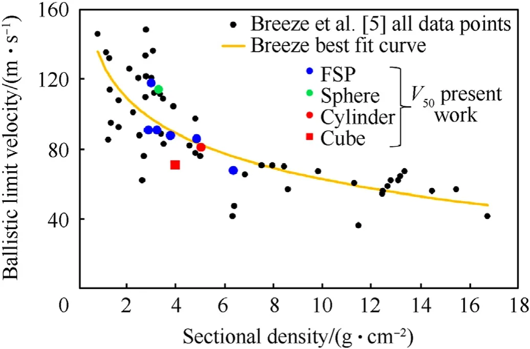
Fig.5.Experimental results of V50 velocities plotted against a sectional density.Skin ballistic limit data from the literature compiled by Breeze et al.[5] and the best fit curve proposed by Breeze et al.[5] are also shown.
3.Results
3.1.Threshold and ballistic limit velocities
The raw experimental data for various fragment shapes and sizes are tabulated in Table 2.The perforation and non-perforation corresponding to each velocity is also indicated.Table 3 showsVthandV50velocities for various fragment shapes and sizes.For all the fragments,VthandV50velocities were consistently close to each other(i.e.,within~10%).Hence,we will refer toV50velocities only in the remainder of the manuscript.
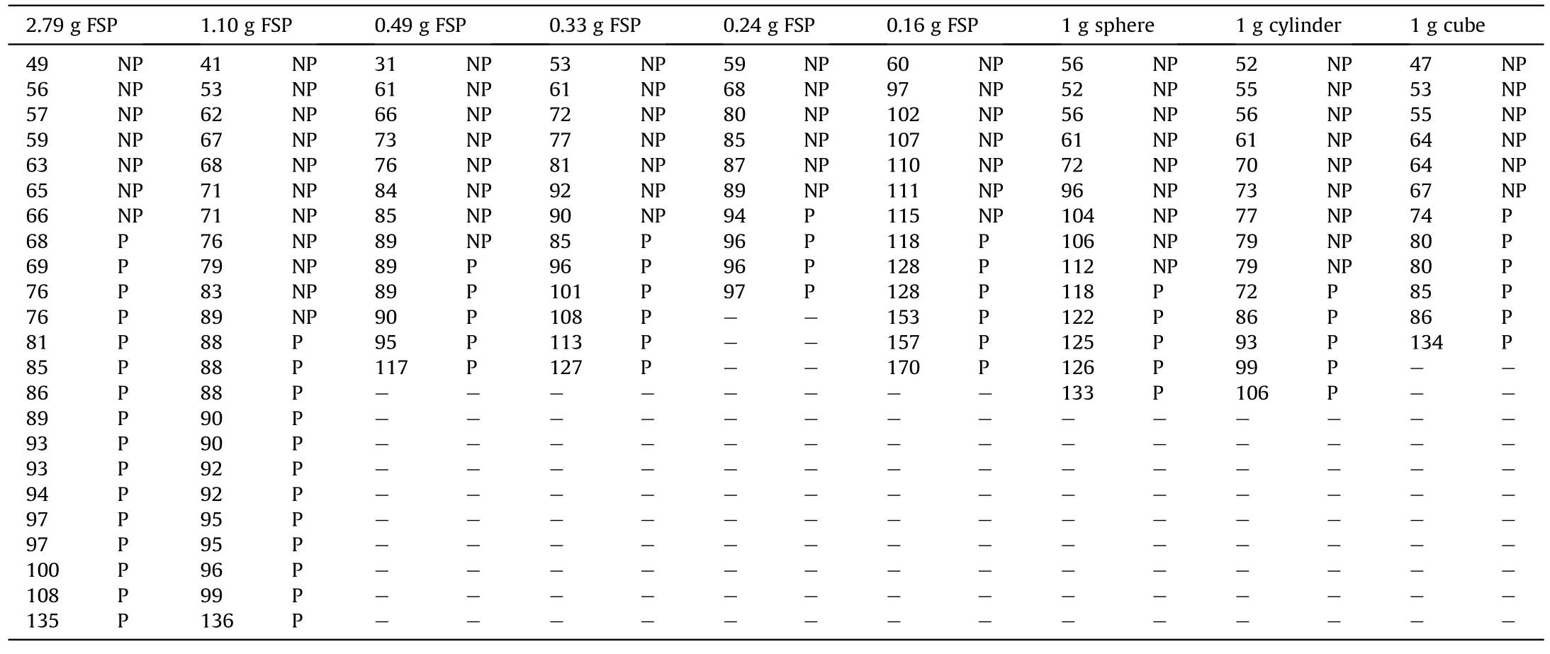
Table 2 Results of impact experiments for various fragments.For each fragment,the first (numeric) column tabulates fragment velocity in m/s and the second column tabulates an event’s outcome.P: perforation,NP: non-perforation.

Table 3 Vth, V50, Eth, E50, and Ea for various fragments studied.
We observe that out of six chisel-nosed FSPs studied (Table 3,Fig.5),V50velocities for four fragment sizes (0.24 g,0.33 g,0.49 g,1.10 g) were not drastically different (within~5%).This can be attributed to the sectional density(mass of the fragment divided by presented c/s area) as discussed later in the discussion section.Compared to these fragments,theV50of the largest fragment(2.79 g)was lower by~24%,and the smallest fragment(0.16 g)was higher by~33%.
For the same fragment size (i.e.,~1 g),the spherical fragment gave the highestV50followed by chisel-nosed FSP,cylindrical,and cubical fragments.With respect to the chisel-nosed FSP of 1.10 g,the difference inV50velocities of the sphere,cylinder,and cube were 34%,-6%,and -16%,respectively.
3.2.Energy and energy density of the fragment
Threshold and ballistic limit energies (Eth,E50) and energy densities (Eth/A,E50/A,Ais the presented c/s area of the fragment)required to perforate the skin are tabulated in Table 3.In general,for chisel-nosed FSPs,threshold and ballistic limit energies(Eth,E50)of the fragment decrease as the size of chisel-nosed FSP is decreased.For these FSPs,the energy densities ranged from 0.1 to 0.20 J/mm2.
3.3.Absorbed energy and absorbed energy density by the skin simulant
Table 3 shows absorbed energy (Ea) and absorbed energy density (Ea/A) by the skin simulant.Absorbed energy by the skin simulant was calculated by subtracting the fragment’s kinetic energy corresponding to residual velocity from the fragment’s kinetic energy corresponding to the impact velocity.The absorbed energy(Ea)tabulated in Table 3 is based on the average absorbed energy corresponding to the three lowest perforation velocities around the threshold velocity.
Results show that for chisel-nosed FSPs,absorbed energy(Ea)by the skin simulant decreases as the size of chisel-nosed FSP is decreased.It is also observed that the absorbed energy (Ea) by the skin simulant is in the range of 73%-85%of the fragment’s ballistic limit energy (E50).It is interesting to note that absorbed energy density (Ea/A) by the skin simulant is in the range of 0.10-0.15 J/mm2,which is reasonably narrow.For the same mass (~1 g),absorbed energy(Ea)and absorbed energy density(Ea/A)were the least for the cubical fragment,followed by cylindrical,chisel-nosed,and spherical fragments.
As we move away from the ballistic limit velocities,the absorbed energy density(Ea/A)increases for the higher impact velocities.For example,for the 1.10 g chisel-nosed FSP,the absorbed energy density is increased by~35%(i.e.,from 0.14 to 0.19 J/mm2)when the impact velocity is increased by~58%(i.e.,from 86 to 136 m/s)with respect to theV50velocity.
3.4.Failure pattern
The schematic of potential failure modes is presented in Fig.6.In general,four failure modes(a)pure shear failure(plugging)[47],(b)pure elastic hole enlargement [47],(c) shear dominated failure(plugging+elastic hole enlargement),(d)elastic hole enlargement dominated failure (elastic hole enlargement+plugging) are possible.
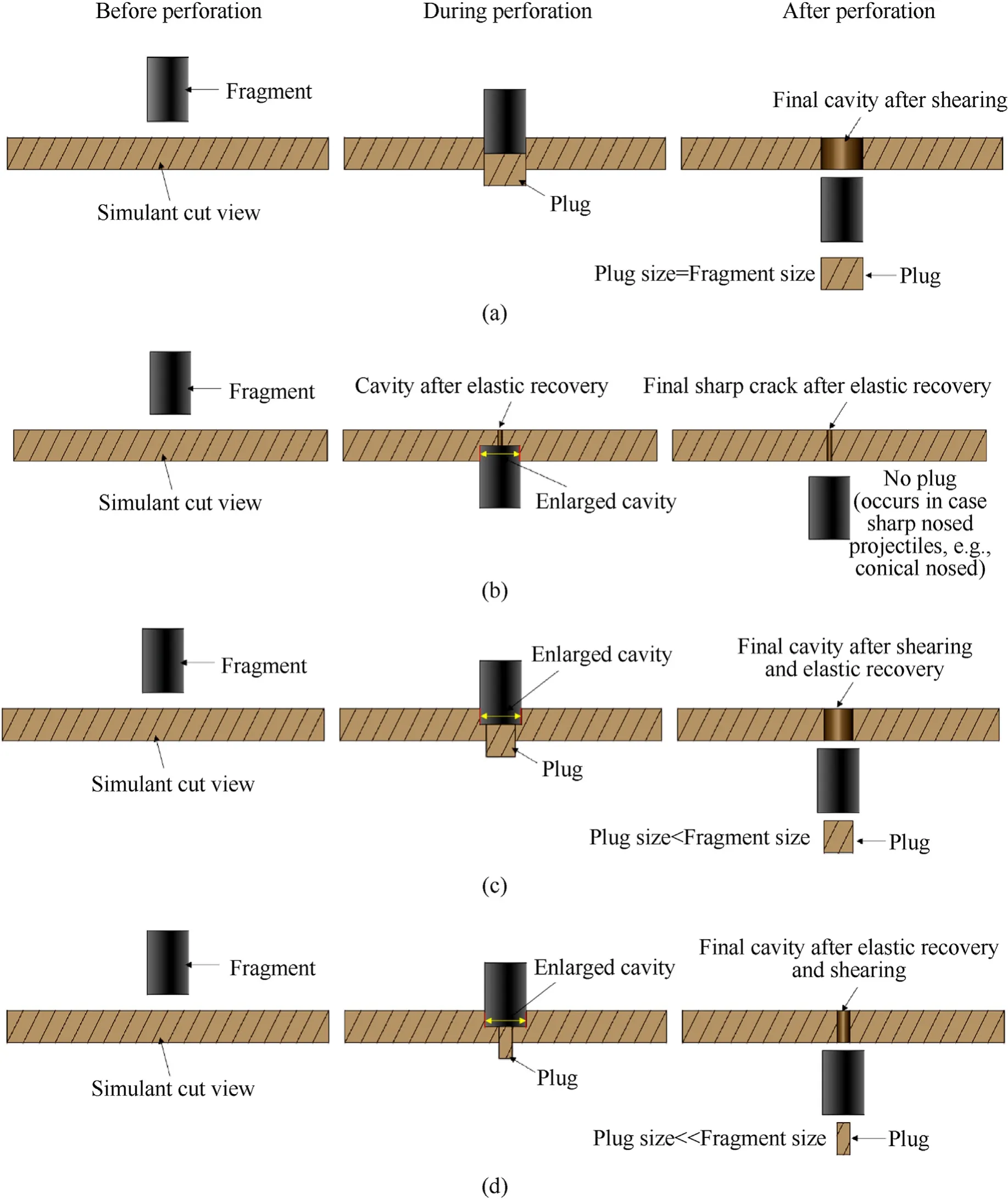
Fig.6.Different mode of failures:(a)pure shear failure(plugging);(b)Pure elastic hole enlargement;(c)Shear dominated failure(plugging+elastic hole enlargement);(d)Elastic hole enlargement dominated failure (elastic hole enlargement+plugging).Fragment size refers to diameter or sides of fragment.
The visual inspection of the actual samples and videography of fragment-skin simulant interaction indicated that skin simulant failed by combined plugging and elastic hole enlargement(Figs.6(c) and 6(d)).When the fragment interacts with the skin simulant(Fig.7(a)),it stretches in the direction of the fragment up to a certain limit(Fig.7(b)).Afterward,the fragment creates a cavity to pass through the target.A plug is generated(Figs.7(b),Fig.8)by developing a shear zone beneath blunt faces.This is followed by the hole enlargement (Fig.7(c)) and elastic recovery of the target(Fig.7(d));that is,elastic hole enlargement.Thus,in these cases,the final diameter of the cavities was less than the respective fragment’s diameter (Figs.9(a)-9(h)).The reduction in the diameter was highest for the spherical fragment (Fig.9(g)).This indicates that in the case of the spherical fragment,the failure process was dominated by the elastic hole enlargement (Fig.6(d)).Further,entry and exit were not in a line that indicated slipping during the perforation(Fig.10).For cylindrical fragment and chisel-nosed FSPs(Figs.9(a)-9(f),9(h)),shear mode failure was dominant(Fig.6(c)).
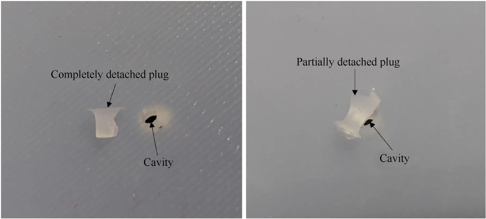
Fig.8.Photographs depicting the generated plug and the cavity.Plug gets either completely or partially detached from the target.

Fig.9.Cavities created by various fragments(shown in red boxes):(a)0.16 g chisel-nosed FSP;(b)0.24 g chisel-nosed FSP;(c)0.33 g chisel-nosed FSP;(d)0.49 g chisel-nosed FSP;(e) 1.10 g chisel-nosed FSP;(f) 2.79 g chisel-nosed FSP;(g) 1 g sphere;(h) 1 g cylinder;(i) 1 g cube.
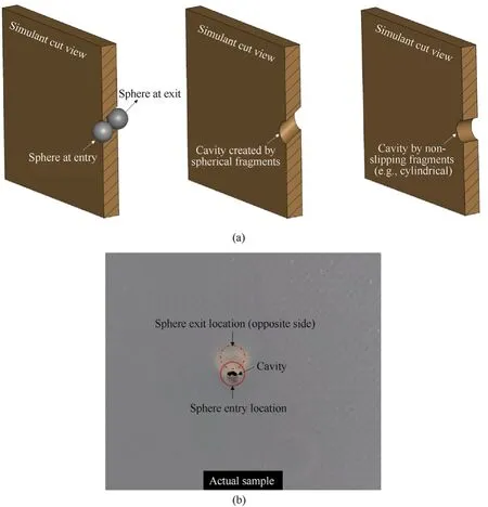
Fig.10.Slipping of spherical fragment during perforation: (a) Schematic based illustration;(b) Photograph of actual sample demonstrating that entry and exit locations are not in the same plane.
Cubical fragments created a square shaped cavity(Fig.9(i)),and shear dominated failure.Further,cubical fragments created small lateral cracks in the target along the corners(Fig.11);lateral cracks were absent for other fragments.During every impact,either no penetration or full penetration was observed with no partial penetration.However,in a few non-perforation cases,a visible mark of the fragment’s impacting face on the target surface was seen.
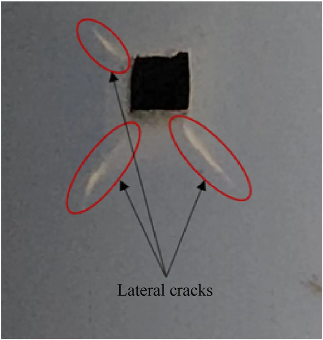
Fig.11.Lateral cracks generated by cubical fragments.
3.5.Deformation of skin simulant during perforation and non-Perforation
Deformation (displacement) of the skin simulant in the direction of impact was estimated from the high-speed images.Our results indicate that(Table 4,Fig.12)the deformation of the skin is influenced by the shape and size of fragments as well as the nature of the event (i.e.,perforation vs.non-perforation).In the case of perforation,maximum deformation was calculated up to the failure(fracture)point.In the non-perforation case,it was calculated up to a point where skin simulant started moving in the opposite direction due to the unloading.
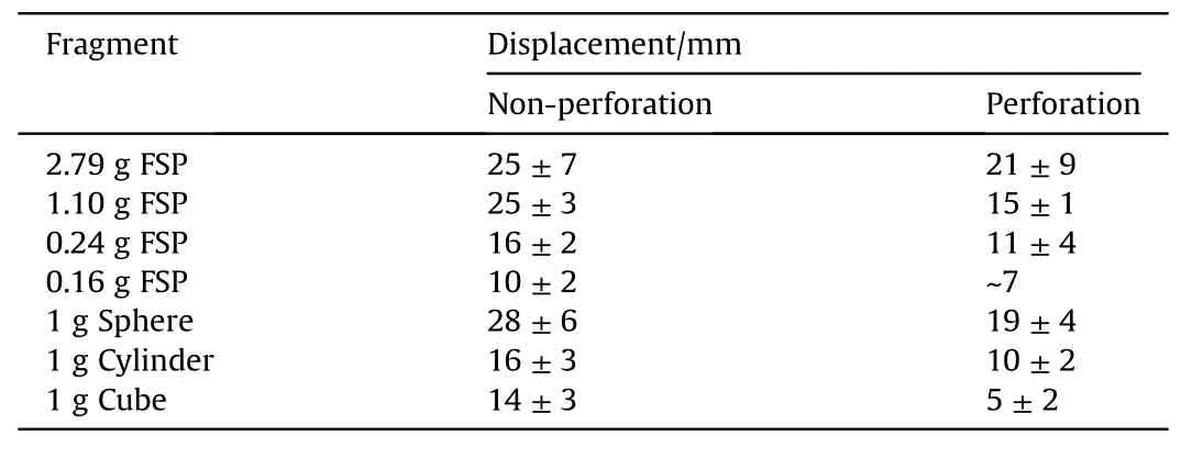
Table 4 Maximum displacement(deformation)of skin simulant during perforation and nonperforation.Values are reported as mean±standard deviation.For a given fragment,mean and standard deviation are based on all corresponding experiments(shots)as reported in Table 2.
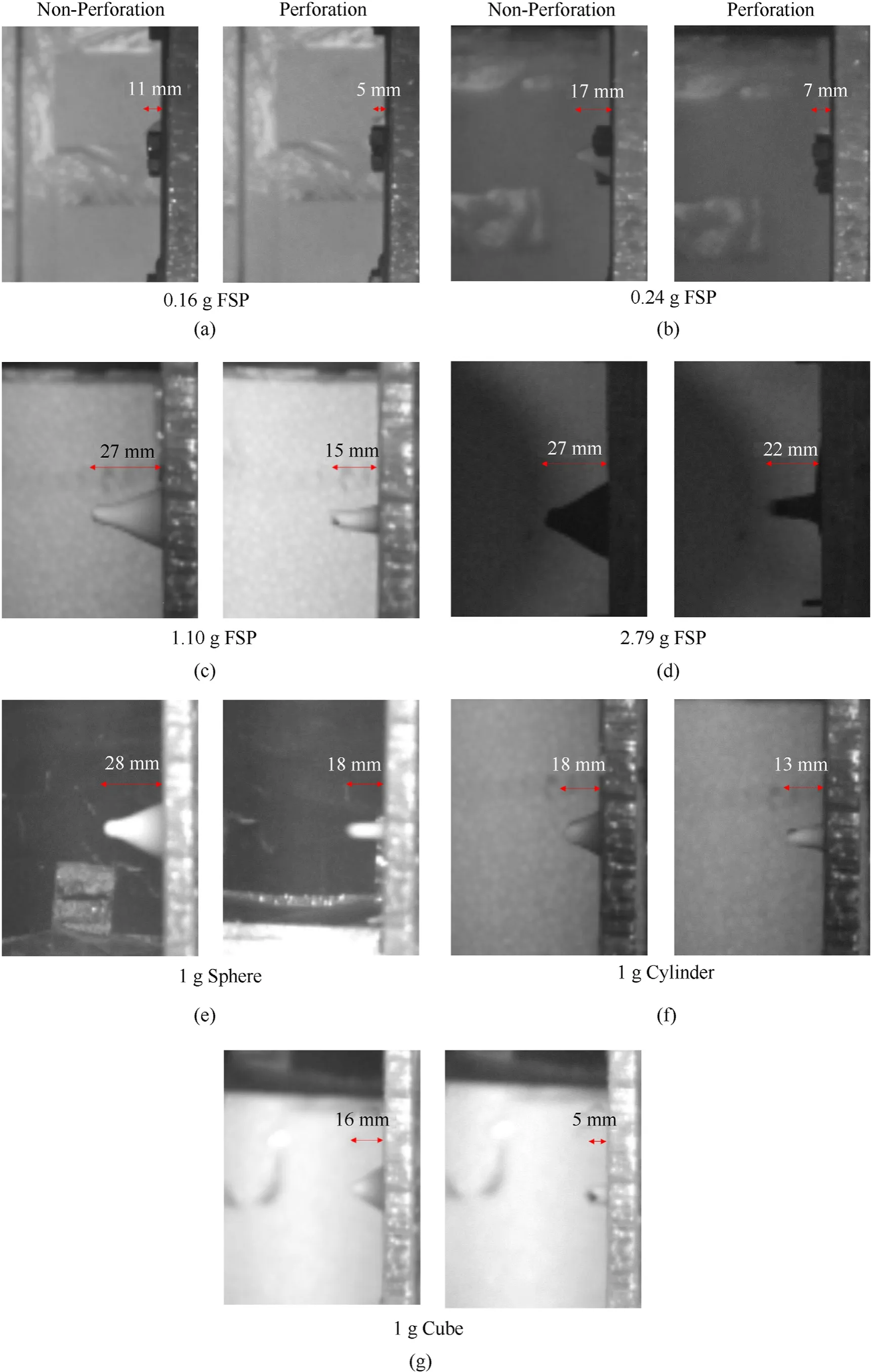
Fig.12.Maximum displacement (deformation) of a skin simulant during non-perforation and perforation.Representative results for each fragment are shown: (a) 0.16 g chiselnosed FSP;(b) 0.24 g chisel-nosed FSP;(c) 1.10 g chisel-nosed FSP;(d) 2.79 g chisel-nosed FSP;(e) 1 g sphere;(f) 1 g cylinder;(g) 1 g cube.
Interestingly,for all fragments,maximum deformation in the case of perforation was less than non-perforation(Table 4,Fig.12).This indicates that the failure is rate dependent and stress driven.In addition,the geometry of the fragment affected the deformation.For the same size (1 g),cubical fragments showed the least deformation (Fig.12(g)),followed by cylinder (Fig.12(f)),chiselnosed FSP (Figs.12(a)-12(d)),and sphere (Fig.12(e)).Sharp edged cubical fragment can perforate the skin easily due to the stress build-up;whereas,in the case of a smooth sphere,the stress build-up is relatively less.
4.Discussion
In this work,the response of the skin simulant against chiselnosed FSPs of various sizes (0.16 g,0.24 g,0.33 g,0.49 g,1.10 g,2.79 g) and regular shaped (spherical,cylindrical,cubical) fragments of size 1 g have been studied.In the reference,the data on the chisel-nosed FSPs is limited (e.g.,see Breeze et al.[5] and references therein).
We observe that fragment shape affects the obtainedV50velocities (Table 3,Fig.5).The highestV50was obtained for a spherical fragment,followed by chisel-nosed FSP,cylindrical,and cubical fragments,respectively.For the chisel-nosed FSPs studied,the obtainedV50were relatively insensitive to the size of the chiselnosed FSPs (Table 3),except for FSP of the smallest (0.16 g) and largest size(2.79 g).
These results are consistent with the findings in the literature.TheV50velocities obtained in this work match reasonably (Fig.5)with a best-fit curve of Breeze et al.[5],particularly for chisel-nosed FSPs and cylindrical fragments.The relative insensitivity ofV50velocities for chisel-nosed FSPs of various sizes can be attributed to the narrow range of associated sectional densities.From the best fit curve of Breeze et al.[5],the reduction in ballistic limit velocity when a sectional density is varied from 3 to 4 g/cm2is 8.50%.The reduction is 15.10%when a sectional density is varied from 3 to 5 g/cm2and 20.49% when a sectional density is varied from 3 to 6 g/cm2.Thus,these reductions are not significant(except for the FSP of the smallest(0.16 g)and largest size(2.79 g))and are within typical experimental scatter and 95% confidence limits [20,23].
For the same size (~1 g),the trend of ballistic limit velocities obtained for various fragment shapes (Table 3,Fig.5) is commensurate with Ref.[48].Cubical fragments have sharp edges and hence can perforate relatively easily compared to chisel-nosed FSP,cylindrical,and spherical fragments [48,49].For a given size,the spherical fragment gave the highest ballistic limit,as it has the lowest sectional density compared to the other shapes.Further,rolling of the spherical fragment(Fig.10)on the skin simulant was observed during the stretching of the skin simulant.Thus,part of the part of energy was lost in the form of rotational energy [50],attributing to the higher ballistic limit for the spherical fragment.Both the surface of the sphere and the surface of the skin simulant were smooth.This caused rolling and subsequent slippage of the sphere on the skin simulant due to the negligible friction between contacting surfaces.
Chisel-nosed FSP and cylindrical fragments gave comparableV50velocities(difference~6%),consistent with the other investigations in the literature comparing the performance of chisel-nosed and cylindrical FSPs [51,52].
Note that in this work,in addition to theV50velocities and absolute energies (Eth,E50,Ea),we have also considered the energy densities(Eth/A,E50/A)of the fragment and absorbed energy density by the skin simulant (Ea/A).The ballistic limit velocity or energy contained in a fragment does not explicitly consider size effects,whereas the energy density(i.e.,the energy of the fragment divided by presented c/s area) explicitly considers the size effect.Thus,in order to compare the perforation performance of various fragments wherein the size is an important consideration energy density is generally preferred.Further,to compare the minimum energy required for the perforation of different targets (e.g.,different organs)energy density is typically considered.For the two fragments with the same energy,the fragment with higher energy density(i.e.,with a lower presented c/s area) indicates a higher likelihood of perforation.
For chisel-nosed FSPs,in general,the energy of the fragment(Eth,E50) and absorbed energy (Ea) by the skin simulant decrease with the size of the chisel-nosed FSP.However,energy densities of the fragment (Eth/A,E50/A) and the skin simulant (Ea/A) are within the range of 0.1-0.20 J/mm2and 0.10-0.15 J/mm2,respectively.These ranges are narrow and hence energy density is relatively insensitive to the size of the chisel-nosed FSPs.Further,the spread in energy density is typically smaller than the absolute energy and ballistic limit velocity.Hence,energy density can be considered as a preferred parameter,especially to compare the ballistic performance of various targets such as different organs or skin simulants.A few of the prior investigations that compare the performance of various targets explicitly prefer energy density over absolute energy and ballistic limit velocity [53-55].We also note that for the same mass (i.e.,~1 g) and various fragment shapes the trend of energies and energy densities of the fragment and skin simulant is commensurate with the trend of the ballistic limit velocities.
Based on prior investigations in the literature[38-40],we chose the skin simulant that closely matched human skin stress-strain response (Fig.3,Table 1).TheV50velocities of the skin simulant obtained in this work are consistent with a best-fit curve of Breeze et al.[5].Further,for all the fragments studied,the energy density,corresponding to perforation,was in the range of 0.1-0.2 J/mm2.Kneubuehl et al.[48] reviewed various skin perforation experiments and estimated energy density of 0.1-0.2 J/mm2for perforation.Thus,based on the obtainedV50velocities and energy densities,the skin simulant used in this work is a reasonable skin surrogate choice.
In this work,we observed combined plugging and elastic hole enlargement failure(Figs.6 and 7).Spherical,cylindrical fragments and chisel-nosed FSPs created a circular cavity,whereas cubical fragments created a square shaped cavity(Fig.9).In the case of the spherical fragment,elastic hole enlargement (Fig.9(g)) was the dominant mode of failure,whereas shear failure was prevalent in all other fragments(Figs.9(a)-9(f),9(h)-9(i)).It is reported in the literature that the spherical projectiles preliminary perforates the target by hole enlargement [47,52,56].Thus,in the case of a spherical fragment,the diameter of the cavity is much smaller than the diameter of the fragment,as depicted in Fig.9(g).Spherical fragment showed slipping during perforation (Fig.10),and cubical fragment created small lateral cracks in the target (Fig.11).Thus,spherical and cubical fragments might be more potent (lethal) for causing widespread damage.These findings are consistent with the findings in the literature regarding the nature and type of perforation [47,56-62].
We observed that the deformation of the skin simulant corresponding to the perforation was lower than the non-perforation(Fig.12).Even though this observation is somewhat non-intuitive is not completely surprising.In our experiments,the strain rate corresponding to perforation velocities was higher than the nonperforation velocities (as perforation velocities were higher and velocities and strain rate are proportional).Thus,the deformation corresponding to the perforation is lower.
Our results indicate that the failure is rate dependent and stress rather than strain dictates the failure during perforation.A few studies have demonstrated the strain rate dependent hyperelastic stress-response of skin[63-67]and silicone rubber[63]in tension.As the strain rate increases,the failure (fracture) stress increases,and strain to failure decreases [63-67].This means that the material strained at a higher strain rate will fail at smaller strain(deformation) values than the same material strained at a lower strain rate.However,for the same material,the failure stress corresponding to the higher strain rate will be larger than the failure stress corresponding to the lower strain rate.Such a failure at highstrain rates is typically called a“stress driven failure”as the failure has initiated because the failure stress value (at that rate) has reached,despite the corresponding strain value being relatively smaller than the low strain rate failure strain value.
Our results underscore that the rate dependent failure process should be adequately taken into account in computational modeling of the ballistic response of the skin and other soft biological tissues.Presently,some of the models(e.g.,see Ref.[67]and references therein,[68]) studying the response of the skin incorporate rate independent hyperelastic model (i.e.,single hyperelastic curve)and do not account for rate dependent failure process.A few investigations incorporate quasi-linear viscoelasticity (e.g.,see Ref.[67] and references therein) at constant strain based on a separate set of stress relaxation experiments.Recently,several strain rate dependent hyperelastic models have been proposed in the Refs.[69-73].Rate dependent failure observed in our work also has implications in developing lethality criteria for soft tissues and in the design of the next generation of personal protective equipment.
5.Conclusions
In this work,the ballistic response of a skin simulant against a fragment impact has been studied experimentally using a pneumatic gas gun setup in a controlled environment.Six chisel-nosed FSPs and three regular shaped fragments have been used.Some of the key findings of the work are summarized below.
· The threshold and ballistic limit velocities were sensitive to the shape of the fragment and relatively insensitive to the size of chisel-nosed FSPs.Spherical and cubical fragments gave the highest and lowest ballistic limit velocities,respectively.The ballistic limit velocities of chisel-nosed FSPs and cylindrical fragments were comparable (within 6%).
· The obtained ballistic limit velocities and energy densities were reasonably consistent with the data in the literature using human or animal skin.
· For chisel-nosed FSPs,energy densities of the fragment and absorbed energy densities by the skin simulant varied over a narrow range.
· The fragments perforated the target by combined plugging and elastic hole enlargement.In the case of spherical fragments,elastic hole enlargement dominated the failure.For all other fragments,plugging dominated the failure.The spherical,cylindrical,and chisel-nosed fragments created circular cavities,and the cubical fragment created a square cavity.
· Spherical fragments showed slipping,and cubical fragments created lateral cracks during perforation.
· The maximum deformation of the skin simulant during perforation was lower than the non-perforation indicating rate dependent,stress driven failure.The shape of the fragment affected the maximum deformation.
These results enhance the current understanding of the response of thin,soft materials against fragment impact and have utility in the development of lethality thresholds,calibration,and validation of computational models.
Funding statement
SG acknowledges financial support from Armaments Research Board under the grant ARMREB-ASE-2018-198.
Declaration of competing interest
The authors declare that they have no known competing financial interests or personal relationships that could have appeared to influence the work reported in this paper.
Acknowledgments
The authors are grateful to the Director,Terminal Ballistics Research Laboratory (TBRL),Chandigarh,India,for granting us permission to publish this research work.We also acknowledge Mr.Yugal Joshi,Scientist,TBRL for useful discussions.
Appendix A.Supplementary data
Supplementary data to this article can be found online at https://doi.org/10.1016/j.dt.2023.04.009.
杂志排行
Defence Technology的其它文章
- Autonomous UAV 3D trajectory optimization and transmission scheduling for sensor data collection on uneven terrains
- Energy balance model to assess the resistance of ballistic protection materials
- Dynamic analysis of bio-inspired helicoid laminated composite plates resting on Pasternak foundation excited by explosive loading
- Research of vibrations effect on hydraulic valves in military vehicles
- Effect of deep cryogenic treatment on the microstructural,mechanical and ballistic properties of AA7075-T6 aluminum alloy
- Influence of quenching medium on the dendrite morphology,hardness,and tribological behaviour of cast Cu-Ni-Sn spinodal alloy for defence application
