Research of vibrations effect on hydraulic valves in military vehicles
2023-12-27MihStosikMykolKrpenkoOlegsPrentkovskisAdmDeptuPuliusSkkusks
Mihł Stosik ,Mykol Krpenko ,Olegs Prentkovskis ,Adm Deptuł ,Pulius Skkusks
a Faculty of Mechanical Engineering, Wrocław University of Science and Technology, Ul.I.Łukasiewicza 7/9, 50-371, Wrocław, Poland
b Faculty of Transport Engineering, Vilnius Gediminas Technical University, Plytins G.27,10105, Vilnius, Lithuania
c Faculty of Production Engineering and Logistics, Opole University of Technology, Ul.Pr′oszkowska 76, 45-758, Opole, Poland
Keywords:Military application Hydraulic valve Vibration Passive vibro-isolation Spring package
ABSTRACT The paper discusses minimizing the effect of external mechanical vibration on hydraulic valves in different military hydraulic drive systems.The current research work presents an analysis of the potential to reduce vibration on the valve casing by installing a valve flexibly on a vibrating surface,i.e.,by introducing a material with known stiffness and damping characteristics between the valve casing and the vibrating surface -a steel spring package or special cushions made of elastomer material or of oilresistant rubber.The article also demonstrates that elastomer cushions placed inside the valve casing -between the casing and the centering springs-can be used as a supplementary or alternative solution in the analyzed method for mitigating the transfer of vibrations.By using materials with appropriately selected elastic and dissipative properties,the effectiveness of vibro-isolation can be increased.The presented theoretical analyzes by linear and non-linear mathematical models have been verified experimentally.
1.Introduction
In 1906,the oil began to replace water as the pressurized fluid in hydraulic systems.With the development of servo valves in World War II,electrical control of fluid power began to enter the commercial sector.Today,the fluid power industry is a multibilliondollar industry,especially in the military area [1].Hydraulics is mostly used in military applications for delivering maximum performance and strength.The ability to handle the toughest work conditions is the most important goal of hydraulics in military equipment and vehicles [2].According to Refs.[2-4] in the different types of military applications like: armored combat vehicles,military recovery vehicles,weapon loaders,mine protected vehicles etc.,actuators are usually operated by high standard hydraulic system.
The hydraulic system of any military application has high requirements for fluids and technical operations (elements work operation)[5].Especially this required is important in case of high responsibility provided by using some of military applications(some of them are shown in Fig.1),like artillery,armored combat vehicles,etc.Wang et al.[6]design adaptive control of track tension estimation using radial basis function neural network,by applying an electro-hydraulic servo system consisting of a hydraulic cylinder,a servo valve,a servo amplifier and sensors.Nie et al.[7] research focused on the dynamic tracking control of ammunition manipulator system,a standard state space model for the ammunition manipulator electro-hydraulic system with inherent nonlinearities and uncertainties considered was established.In the Chen et al.[8]research,a modelling method for investigating the dynamic characteristics of a hydraulically driven shell manipulator with revolute clearance joints was done,the model accounts for the effect of the clearance,the flexibility of the rotating beam,and the coupled dynamic characteristics of the hydraulic cylinder.Another research is focused on the general design principle of artillery for firing accuracy[9]or on a novel variable topology design for a multi-flexible ejection mechanism[10],in both cases a hydraulic systems element under research.
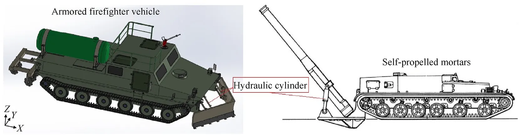
Fig.1.Examples of use hydraulic drives in military vehicle applications.
By detail analyses of presented above research,it should be pointed out that all the researchers included a problem of high vibration and pressure fluctuations.The problem of vibration is currently directly response to firing accuracy of military applications,in which actuators are operated by hydraulic system valves.That is why it is critical requirement to solve the problem of the possibility of minimizing the impact of external mechanical vibration on hydraulic valves that operate the actuators of military applications.
In real conditions,hydraulic valves,including directional control valves (DCVs),are subjected to mechanical vibration [11,12].The vibrations have different sources -they result inter alia from the unbalance of machine rotating parts,from variable loads,from the movement of the machine on an uneven surface,etc.[13].Most generally,the problem of vibrations transferred by a machine or a device can be divided into three basic and related stages:vibration sources;vibration transfer paths;vibration effects.
A working hydraulic system is also a source of mechanical vibration,caused mainly by percussive pressure changes and by the periodical character of the operation of positive displacement pumps.Vibrations generated in such a manner have various frequencies and consequently-different transfer paths.Any military mobile machine moving on an uneven surface may be subjected to excitations within the frequency range from 0.5 to 250 Hz [14,15],which are due to the mechanical connections of the hydraulic system elements through conduits and shared mounting elements,which also contribute to the generation and propagation of noise[16].This frequency range includes excitations that are due to the(combustion)engine as well as due to the kinematics of the positive displacement pump,and which are manifested by pressure pulsations in the hydraulic system of the machine[17-19].Such pressure pulsations have significant consequences,including vibration on hydraulic conduits [16,20].On the other hand,vibration due to air resistance is within the frequency range of 250-16,000 Hz and is caused by the separation of the air stream from the elements of the machine [21,22].
Vibration entails a number of negative effects,frequently exciting vibrations of the control elements in hydraulic valves[23,24].These elements are responsible for defining the size of the gaps in hydraulic valves.As the valve control element(e.g.a spool,a poppet)starts to vibrate,the gap surface area changes.This change manifests itself in the hydraulic system by efficiency pulsation and as a result -by pressure pulsation.The components of this pulsation spectrum correspond to the vibration spectrum components of the excited element.The above fact is confirmed by the results presented in Fig.2.

Fig.2.Amplitude-frequency spectrum of pressure pulsation in a hydraulic system with kinematically excited: (a) Single-stage pressure relief valve with a 20 Hz excitation frequency;(b) Single-stage conventional electric DCV with a 60 Hz excitation frequency.
The graphs in Fig.2 show the harmonic components of the spectrum which correspond to the efficiency pulsation of the displacement pump (approx.242 Hz) and the harmonic components of the spectrum having frequencies corresponding to the frequencies of the external mechanical vibrations acting on the valve cases:for Fig.2(a) it is 20 Hz and for Fig.2(b) it is 60 Hz.
The resonant frequencies of the hydraulic valve control elements (poppets,spools) are below 100 Hz [25,26].This frequency range is particularly dangerous for people,as the resonance frequencies of important internal human organs are below 100 Hz[21,27]as well.Pressure pulsations in low frequencies may result in unstable operation of hydraulic receivers,contributing inter alia to their imprecise operation.Such pulsations may also induce infrasound.
2.Review of related research
The problem of vibration in valves has been addressed in the literature for a long time.However,many authors focus in their research on self-excited vibration of valve control elements.For example,the authors of publication[28]describe theoretically and experimentally the mechanism of self-excited vibration on a pressure relief valve in a simple vessel-valve-pipe system.The authors of publication [29] address the issue of leaking spherical valves subjected to periodical vibration,leading to significant pressure pulsation amplitudes.They have built a simplified model in order to explain the mechanism of self-excited vibration.They have also offered valve stability criteria,which suggest that this stability depends on the relationship between the inertia of the main line and the leakage kinetic energy,the leakage reduced velocity,the seal surface area ratio,the geometry of the main line and the hydraulic losses.Results of more advanced numerical CFD studies are presented in publication[30].Its authors analyze on the one hand,vibration of a valve ball excited with the working fluid flow and on the other-the effect of the ball vibration on the valve casing.They formulate valve stability criteria.Based on the compared results of numerical calculations and experiments,they conclude that CFD methods allow a good similarity with actual results and may be used in simulations of vibration on hydraulic systems.The authors of publication[31]investigate the influence of vibration on the dynamics of a nozzle-flapper servo valve.They indicate that this system has a significant role in the operation of the entire servo valve.The aim of their work is to define the influence of disturbances (such as vibration) on the dynamic characteristics of the operation of the nozzle-flapper system.Being important elements of position control systems,servo valves are particularly sensitive to vibration [32].Moreover,the authors of publication [33] indicate that vibration on the nozzle-flapper control pair may be due to variable forces from the pulsation flow of the liquid in the servo valve.Vibration excited in such a manner was subjected to FEM and CFD analyses.The results allowed the authors to draw a conclusion that the vibration on the flapper is excited by the pressure pulsation in the servo valve,as its frequency is similar to the eigenfrequency of the flapper.The authors of publication[34]focus on self-excited vibration of a single-stage pressure relief valve and formulate its stability criteria by allowing for the flow rate through the valve and the damping of the valve popper.On the other hand,the authors of publication [35] offer only a general conclusion regarding hydraulic valves,in which they observe that the valves are sensitive to mechanical vibration and in order to mitigate the effect of this vibration they suggest installing rubber cushions,however without proposing any criteria that such cushions should meet in order to effectively isolate this vibration.
Manufacturers of hydraulic elements seldom provide requirements regarding the operating conditions of their products from the perspective of their(e.g.valves)resistance to mechanical vibration.Such rare cases include the Parker-Hannifin D1FP proportional DCV -its technical specification defines the allowed value of mechanical vibration due to spool resistance at approx.250 m/s2[36].Tests of hydraulic valve resistance to mechanical vibration are typically based on such standards as EN 60068-2-6:2008[37],as in the case of the D1FP valve.Such tests can be also performed on the basis of other standards and methods described in Polish and international publications.PN-EN 60068-2-57:2013-12 [38] describes methods for testing sub-assemblies,devices and other electrotechnical products,including electrically controlled hydraulic valves which may be subjected during operation to short-duration pulsation or oscillation forces due to e.g.seismic phenomena,explosions or machine vibration.The product is excited with a number of sine beats with constant frequencies.PN-EN 60068-2-6:2008 [39] provides a method for testing subassemblies,devices and other products which may be subjected during transportation or operation to harmonic vibrations mainly due to rotating,pulsating or oscillating masses.Such excitations occur inter alia on ships,planes,aircraft,and land vehicles[40,41].The tests include valve resistance to mechanical vibration within the frequency range from 5 to 3000 Hz and may identify a critical frequency,i.e.such at which it is possible to observe either a product malfunction,lowered properties resulting from the vibration,or mechanical resonances (e.g.of the valve control element).On the other hand,PN-EN ISO 4413:2011 [42] provides inter alia requirements for the assembly of hydraulic valves (as well as pumps,actuators,filters,etc.),with the only general conclusion that the influence of gravity and vibration on the valve must be taken into account.
The standards describing resistance to vibration can be thus concluded to define the allowed level of internal mechanical vibration that can adversely impact a machine,device or its element.In high-precision industry,the maximum acceleration of approx.0.981 m/s2[43,44] is accepted as a standard value protecting the vibration resistance of measuring apparatus and devices.This value has been defined in experiments which demonstrated that such vibration does not influence the operation of these devices.Turbomachines,however are allowed to be subjected to external mechanical vibration greater than 9.81 m/s2,which does not affect their operation.
Moreover,vibration of hydraulic valve control elements is accompanied by noise with the spectrum components inter alia in low frequencies.The noise level is an important criterion in evaluating the quality of machines and devices.As regards noise protection,EU Directive 2006/42/EC [45] defines inter alia the following requirements: the machine must be designed and constructed in such a manner that the risks due to the emitted noise are reduced to the lowest level,as allowed by current technical possibilities and using the available noise reduction means,especially at the source of the noise.The above is confirmed by the requirements presented in EU Directive 2005/88/EC [46] on the allowed sound power levels of noise emitted into the environment by machines.For example,in the case of a wheeled loader with a net installed power of up to 55 kW,this sound power level was 104 dB until January 3,2002,while since January 3,2006 it has been lowered to 101 dB.Moreover,a new EU Directive 2007/30/EC[47] introduced on June 28,2008 regulates noise protection in all EU Member States.It lowers the permissible maximum value of noise on the position of machine operator,defined from the average value of an 8-h exposure,to the level of 80 dB (A) (the previous value had been 85 dB (A)).
Introducing a material which,from the perspective of reducing the transferred vibration amplitudes and frequency ranges,has advantageous elastic and dissipative properties should lead to a reduction in vibration amplitudes of valve control elements and thus also in pressure pulsation in the hydraulic system.By effectively reducing the vibration of the directional control valve body,the vibration of the spool will be reduced.This will reduce the variation of the directional control valve throttling gap value,and this will reduce the throttling of the flowing hydraulic oil.Consequently,a reduction in the harmonic components of the pressure pulsation spectrum corresponding to the frequencies of external mechanical vibrations can be expected.
The studies reported in the literature so far do not mention the excitation of the directional control valve spool under the influence of external mechanical vibrations.In addition,in the theoretical and experimental considerations presented in the literature,the hydraulic valve is attached to the base (e.g.a vibrating vehicle frame) in a non-susceptible manner.In this paper,the problem of vibration excitation of the directional control valve spool is noted and the effect of this vibration -changes in the pressure pulsation spectrum of a hydraulic system with a vibrating directional control valve-is indicated.In addition,a mathematical model is presented which,using passive vibration isolation elements,is useful in assessing the effectiveness of prone attachment of the directional control valve to a vibrating substrate.
3.Application of elastic support in the reduction of vibration on the DCV casing
The above analyses demonstrate a need to limit vibration on the valve casing,which will result in limited vibration on the valve spool.The following is a theoretical analysis of vibration on the casing of a proportional directional control valve mounted flexibly in custom-designed holders accommodating packets of springs with known characteristics or elastomer materials with experimentally determined elastic and dissipative properties.
The evaluation of how effectively the hydraulic valve is isolated from external mechanical vibration was performed with the use of a valve mounted in a special holder,in which it was supported on one side with springs,as illustrated in Fig.3(a).Fig.3(b) shows a simplified model of a single-mass system in the holder,supported on one side with springs.

Fig.3.View of special valve holder:(a)Valve holder:1-Hydraulic valve(e.g.DCV),2-Holder plate,3-Spring preload bolts,4-Springs,5-Protective fasteners,6-Stop plate;(b) Model of a single mass system in the holder supported on one side with springs.
The list of important symbols in the research is provided in Table 1.The holder is designed in such a manner that the valve is tied with springs having an artificial ratecz,and when moving along the holder plate (element 2 in Fig.3(a)),it is subjected to friction according to the dry friction model.Moreover,after the clearancel0(see Fig.3(b))is eliminated,the valve casing is in contact with the fasteners protecting the valve from being removed (element 4 in Fig.3(a));this contact was assumed to have a character of a dry metal-to-metal friction.The valve is supported with springs on one side,and on the other side it rests directly on a rigid stop plate(element 6 in Fig.3(a)).The mathematical model Nr.1 of such a system can be represented in the following equation:

Table 1 List of important symbols in the research.
where,m2-valve mass;cz-artificial rate of springs supporting the valve;x0s-spring preload;μ2-dry friction coefficient for the friction between the valve casing and the protective fasteners;μidry friction coefficient for the friction between the valve casing and the holder plate;g -gravitational acceleration;w -kinematic excitation;H -Heaviside step function.
In Fig.4(a) shows a schematic diagram of the hydraulic system provided with the DCV.In more detailed analyses,the flexibly supported proportional DCV can be considered as a two-mass system comprising a spool having a massm1and a valve casing having a massm2-as shown in Fig.4(b).

Fig.4.Model schemes: (a)Schematic diagram of the tested element system:1-Feed pump;2-Pressure relief valve;3-Tested element (the 4WRE 6 E08-12/24Z4/M proportional DCV);4-Adjustable throttle valve;(b) Model of a two-mass system in the holder supported on one side with springs.
The mathematical model Nr.2 of such a system,allowing for the configuration of the hydraulic system and the flow of the working fluid,can be expressed in the following system of equations:
The first equation describes the balance of forces acting on the spool excited into motion by the vibrating valve casing,to which it is connected by the centering springs and the friction in the slidesleeve pair.The second and third equations describe the balance of flow rate in the hydraulic system operating without the pressure relief valve.The fourth equation describes the forces acting on the valve casing in the analyzed case.After the clearance l0 has been eliminated,the valve casing is assumed to be in frictional contact with the protective fasteners.The model is built on the basis of the following simplified assumptions.
· The properties of the working fluid are not changed;
· The coulomb friction in the slide-sleeve pair is ignored;
· The contact between the valve casing and the holder is represented by the Coulomb friction;
· After the clearance is eliminated,the contact between the valve casing and the protective fasteners is represented by the Coulomb friction;
· The spring characteristics are linear and described by stiffnessc;
· The description of the hydraulic system is based on a lumped parameter model.
The solution for the model for artificial ratecz=86 000 N/m is shown in Fig.5 as a relationship between the acceleration amplitude of the valve casing vibrationa2and the acceleration amplitude of the excited vibrationa0.Some of the important parameter values used in the calculations:m1=0.0344 kg;m2=4.5 kg;l=36.6 × 10⁻³m;dt=12×10-3m;h=1.5×10⁻⁷m;μ=0.22 N/m;ρ=900 kg/m3;ξ=1.78;c1=4884 N/m;l0=0.2 × 10-3m;μ2=0.1;μi=0.12;Qp=1× 10⁻⁴m3/s,ap1=2.5× 10-11m4s/kg;Aa=1.5×10-6m2;pz≈0 MPa;ck1=0.62×10⁻¹²m5/N;Cq1=0.6.External kinematic excitation is described with the following harmonic function w(t)=w0(f)sin (2πft),in which w0(f)-excitation amplitude (m)corresponding to the excitation frequency;f-kinematic excitation frequency(Hz).For frequency f=10 Hz,w0(10)=3.76×10⁻³m;for f=15 Hz,w0(15)=2.25×10⁻³m;f=20 Hz,w0(20)=1.33×10⁻³m;for f=25 Hz,w0(25)=0.84 × 10⁻³m;for f=30 Hz,w0(30)=0.48 × 10⁻³m;for f=35 Hz,w0(35)=0.41 × 10⁻³m;for f=40 Hz,w0(40)=0.37 × 10⁻³m;for f=45 Hz,w0(45)=0.27 × 10⁻³m;for f=50 Hz,w0(50)=0.21 × 10⁻³m;for f=55 Hz,w0(55)=0.15 × 10⁻³m;for f=60 Hz,w0(60)=0.052× 10⁻³m.

Fig.5.Model Nr.2.Vibration acceleration amplitude of the proportional DCV casing a2 related to the vibration acceleration amplitude of the excitation a0 for f from 10 to 60 Hz.
The criterion for an effective vibro-isolation for a particular excitation frequency was defined in such a manner that the relationship between the valve casing vibration acceleration amplitude and the excited vibration acceleration amplitude is less than 1[22],i.e.a2/a0<1.This relationship can be referred to as the "transfer function".
The above results(Fig.5)indicate that the spring packet used in the experiment meets the criteria of effective vibro-isolation [22]for excitation frequency ≥30 Hz.However,in the frequency range<30 Hz the valve casing vibration increases,which is an adverse effect.
In order to broaden the frequency range of effective vibroisolation,the present research also focused on a case in which the DCV was mounted in a special holder and supported on both sides by springs with known characteristics.The spring packets were installed between the valve casing and the holder,as illustrated in Fig.6.
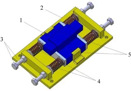
Fig.6.Valve holder Nr.2:1-Hydraulic valve(DCV);2-Holder plate;3-Spring preload bolts;4-Springs;5-Protective fasteners.
The holder is designed in such a manner that the valve is tied with springs having an artificial ratecz,and when moving along the holder plate (element 2 in Fig.6),it is subjected to friction according to the dry friction model.The valve is supported with springs on both sides.Fig.4(a) shows a schematic diagram of the hydraulic system provided with the DCV.
As in the previous case,the mathematical analysis of the valve vibration can be based on the model of a two-mass system.For the two-mass system,the proportional DCV model,constructed with allowance for external vibration and operating in a hydraulic system shown in Fig.4(a),is represented in the form of a system of four equations (model Nr.3):
The first three equations of the model Nr.3 (Eq.(3)) are analogical to the equations of the previous model Nr.2(Eq.(2)),as neither the spool-casing system nor the structure of the hydraulic system has changed.Some difference is found in equation four,due to the different design of the holder.In this case,it was also assumed that after the clearancel0is eliminated,the valve casing is in frictional contact with the protective fasteners.Further,in this study,equation four of the model Nr.3(Eq.(3))will be modified so as to describe the various characteristics of the proposed vibroisolation elements.
The model Nr.3 also allows for the contact of the valve casing with the protective fasteners 5,as shown in Fig.6.Fig.7 shows the numerical solution in the form of the “transfer function.”The parameter values of the valve,the hydraulic system and the valveholder system,which were used in the calculations,have not changed and are identical to those used in the previous model(model Nr.2).External kinematic excitation is described with the following harmonic function w(t)=w0(f)sin(2πft),in which w0(f)-excitation amplitude (m) corresponding to the excitation frequency;f-kinematic excitation frequency(Hz).The values of the kinematic excitation parameters were identical to those used in the previous model.

Fig.7.Model Nr.3.Vibration acceleration amplitude of the proportional DCV casing a2 related to the excited vibration acceleration amplitude a0 for f from 10 to 60 Hz.
The simulation results indicate that the amplitude of the casing vibration acceleration has significantly increased for the frequency of approx.20 Hz.This phenomenon is due to resonance,as the mass of the vibrating valve is approx.4.5 kg and with the artificial rate of the holder springczbeing 86,000 N/m,the resonance occurs at a frequency of approx.22 Hz.Therefore,in the range of 10-30 Hz,the amplitude of the valve casing vibration acceleration increases -vibro-isolation is thus ineffective.Effective vibro-isolation is observed for frequencies above 35 Hz.
Such valve isolation means should be proposed,which will increase the effective isolation zone while reducing the amplification zone of the valve casing vibration.This problem has been solved with the use of the “Black Box”method,see Fig.8.
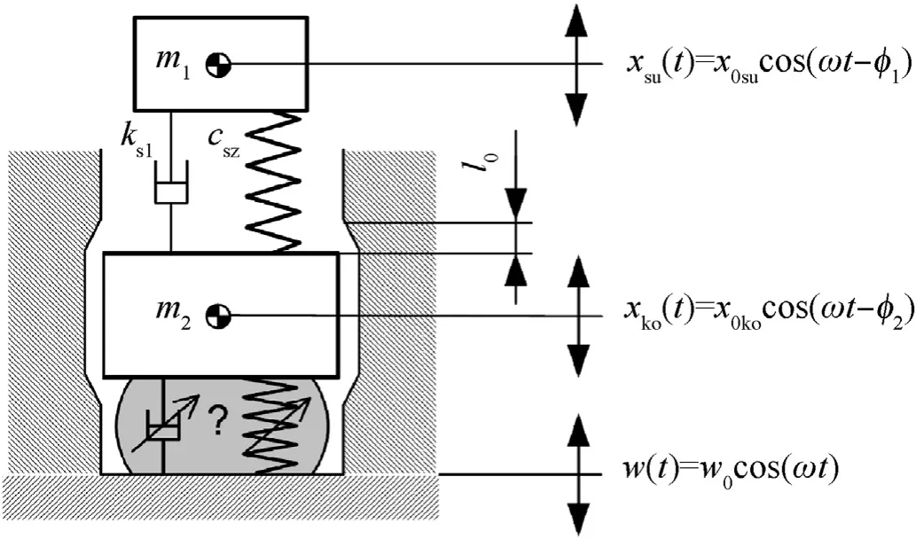
Fig.8.The “Black Box”method in valve vibro-isolation.
Various forms of the isolation element can be assumed.If a material having a linear stiffness and a damping characteristic expressed as
It is introduced between the valve casing and the vibrating holder,and if an assumption is made that the clearancel0is not eliminated,then equation four in the equation system from Eq.(3)can be expressed as (model Nr.4)
With the assumed values of parameterscz=20,000 N/m andk2=50 N/m and subsequentlyk2=250 N/m,an evaluation can be made of how damping modifications influence the effectiveness of isolating the valve casing from the vibrating surface.A similar evaluation can be made for the influence of stiffness changes on the effectiveness of isolating the valve casing from the vibrating surface,by introducingcz=120,000 N/m.Fig.9 shows the "Transfer Function" values for different damping valuesk2.Increasing the damping value (while keeping the stiffness value constant) in the resonance range results in improved vibration isolation effectiveness(lower transfer function values).Increasing the stiffness(while keeping the damping value constant) shifts the resonance region and increases the transfer function value significantly.

Fig.9.Model Nr.4.Vibration acceleration amplitude of the proportional DCV casing a2 related to the excited vibration acceleration amplitude a0 for f from 10 to 60 Hz.
The analysis of the data presented in Figs.7 and 9 indicate that the use of a vibro-isolator having linear characteristics and different values of parametersczandk2allows the range of the valve casing vibration amplification to be limited,and the effective isolation zone,i.e.the range for thea2/a0<1 relationship-to be increased.Further improvement of effective isolation of the valve casing from the vibrating surface can be achieved with the use of isolators having non-linear characteristics.
If a material having a non-linear stiffnesscz(xko-w)2and a damping proportional to the relative velocityis introduced between the valve casing and the vibrating holder,and if an assumption is made that the clearancel0is not eliminated,then equation four in the equation system of model Nr.3 can be expressed as (model Nr.5)
If the set of parameters is supplemented withcz=20,000 N/m2andk2=50 N/m,or for example in order to define the share of damping in the process of reducing vibration on the valve casing,withk2=250 N/m,the result is a numerical solution showing vibration on the valve casing,shown in Fig.10.Additionally,Fig.10 shows the values of the "Transfer Function".
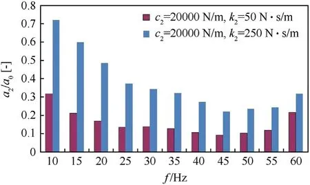
Fig.10.Model Nr.5.Vibration acceleration amplitude of the proportional DCV casing a2 related to the excited vibration acceleration amplitude a0 for f from 10 to 60 Hz.
In this case,an increase in the damping value for a particular stiffness is observed to result in increasing values of the "Transfer Function".However,unlike in the case of using a material with linear characteristics of stiffness and damping,in this case the value of the "Transfer Function" is less than 1 in the entire range of the discussed frequencies.
If the surface vibration is isolated with the use of a vibro-isolator having non-linear damping characteristics (k2=250 N2/m2) and linear stiffness (cz=20,000 N/m),Eq.(4) then the ratio of the vibration amplitude on the valve casinga2to the amplitude of surface vibrationa0for illustrative excitation frequencies can be represented as in Fig.11.
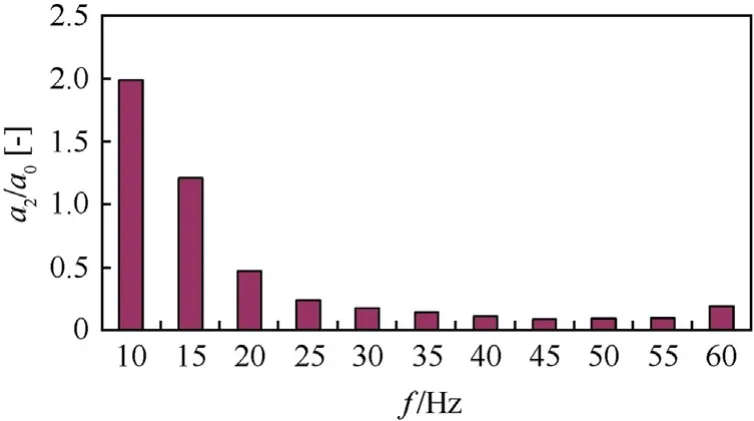
Fig.11.Non-linear damping model.Vibration acceleration amplitude of the Mannesmann-Rexroth 4WRE 6 E08-12/24Z4/M proportional DCV casing a2 related to the excited vibration acceleration amplitude a0 for f from 10 to 60 Hz.
The range of effective vibro-isolation for such an isolator model is observed to also increase and,importantly,to include the resonance frequency of a spool in a typical single-stage DCV.The proposed mathematical model can be used in evaluations of the effectiveness of the employed vibro-isolation system.
4.Experimental verification of the possibilities to reduce vibration on a hydraulic valve with the use of spring packets and elastomer elements
4.1.Experimental tests of vibration reduction with the use of steel spring packets
The conclusions resulting from the above theoretical considerations and numerical calculations,as well as the technical possibilities for implementing the proposed solutions,were verified in experimental tests which consisted in mounting the Mannesmann-Rexroth 4WRE 6 E08-12/24Z4/M proportional DCV in custom holder 1 (Fig.3(a)) and in custom holder 2 (Fig.6),as shown in Fig.12.
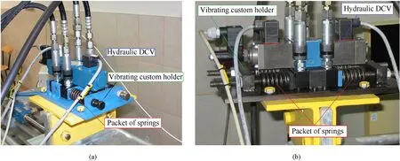
Fig.12.Photographs of research objects:(a)Proportional DCV during experimental tests mounted in custom holder 1 and supported with springs on one side;(b)Proportional DCV during experimental tests mounted in custom holder 2 and supported with springs on both sides.
The proportional DCV was placed in the custom holder Nr.1(Fig.3(a))and supported on one side with two springs having a rate of 43,000 N/m each.Such a parallel spring arrangement displayed high artificial ratecz=86,000 N/m,and the preload was set to 2 mm.The external vibration was excited by the Hydropax ZY25 linear drive simulator.Subsequently,the tests were repeated,with the stiffness of an individual spring in the parallel arrangement modified to 22,000 N/m resulting in the artificial spring ratecz=44,000 N/m.Fig.13(a) shows the test results in the form of a relationship between the amplitude of casing vibration acceleration and the amplitude of excited vibration acceleration.
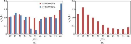
Fig.13.Vibration acceleration amplitude of the proportional DCV casing a2 related to the excited vibration acceleration amplitude a0 for f from 10 to 60 Hz: (a) Proportional DCV supported on one side with two springs;(b) Proportional DCV supported on both sides by springs.
The chart in Fig.13 shows that a system comprising springs with an artificial ratecz=86,000 N/m and a proportional DCV with a mass of 4.5 kg has two zones:a resonance zone(for the frequency range of approx.20 Hz) and an isolation zone above it (except the 60 Hz frequency).The casing vibration amplitude increases in the first zone and slightly decreases in the second zone.However,the custom holder Nr.1 and the set of two parallel springs do not meet the expectations regarding effective vibro-isolation,as the slight decrease of the ratio of vibration acceleration amplitudes in the effective isolation zone is accompanied by a significant increase,as much as 30%,of the vibration acceleration amplitude in the resonance zone(15-20 Hz).
During further tests,the proportional DCV was placed in the custom holder 2(Fig.6)and supported on both sides by springs in such a manner that two parallel springs were located on each side of the valve.Such a parallel spring arrangement displayed high artificial ratecz=86,000 N/m,and the preload was set to 2 mm.The cumulative results for the excitation frequency range of 10-60 Hz are shown in Fig.13(b).A comparison of the results in Figs.13(b)and 7 show that effective vibration isolation of the valve for the selected vibration isolator model (a set of springs with linear characteristics and known stiffness) occurs for vibration frequencies above 25 Hz (for experimental results) and above 30 Hz(for results from the numerical solution of model No.3).
This spring set and holder type allowed a decrease in the ratio of casing vibration acceleration amplitudes to external excitation amplitudes in the range of 25-60 Hz.The holder vibro-isolation also proves more effective for the holder with double-sided support(Fig.6) than for the holder with single-sided support (Fig.3(a)),as illustrated in Fig.14.A comparative analysis of the results shown in Fig.14 indicates that,outside the resonance zone,a much more effective reduction in the vibration of the directional control valve body is obtained by supporting the valve with spring packs on both sides.The greatest reduction(about 4 times)of the transfer function value is at a frequency of 60 Hz.A significant decrease in the transfer function value can be observed already at 25 Hz.
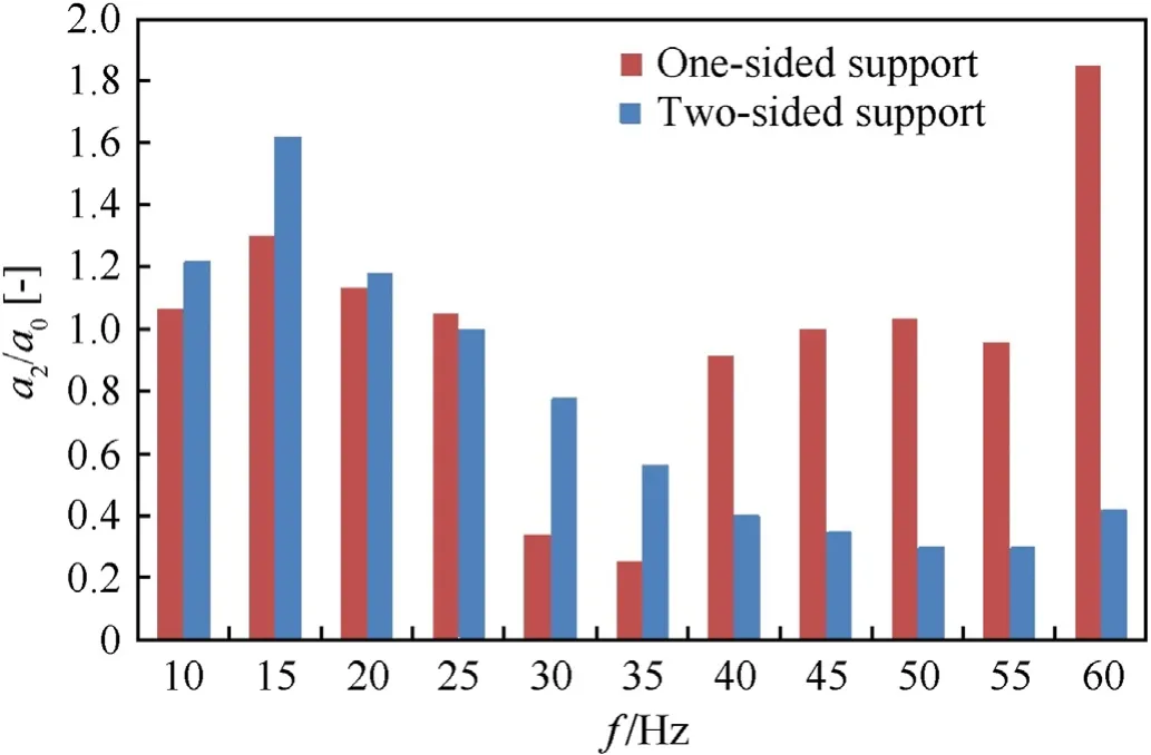
Fig.14.Comparison of one-sided support and two-sided support with springs vibration acceleration amplitude of the proportional DCV casing a2 related to the excited vibration acceleration amplitude a0 for f from 10 to 60 Hz.
The above-presented results indicate that the acceleration amplitude of vibration on the valve casing can be reduced by implementing a spring packet.However,this solution requires additional space to be provided for the springs.Moreover,the acceleration amplitude values of vibration on the casing increase in the resonance zone.The problem of additional space occupied by the vibro-isolation system and of further increasing the vibroisolation effectiveness can be solved by implementing for example isolators made of elastomer materials.
4.2.Experimental tests of vibration reduction with the use of elastomer materials
The space occupied by the vibro-isolation system can be limited by using special elastomer cushions.The tested DCV casing was vibro-isolated with the use of cushions made of elastomer materials and placed between the casing and the holder of the simulator table,shown in Fig.15.
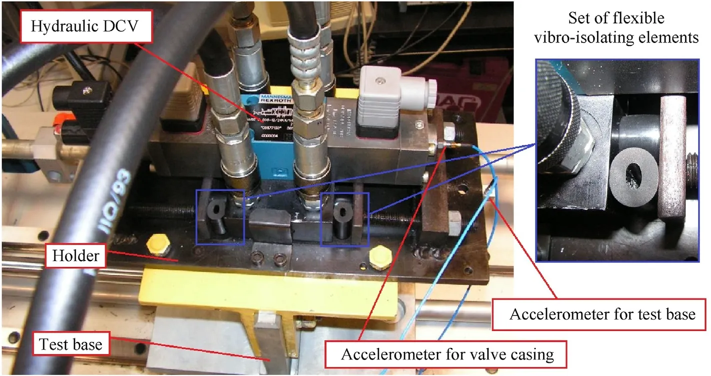
Fig.15.Hydraulic DCV installed in the holder with the use of flexible vibro-isolating materials.
During the tests,the vibration acceleration was measured for both the simulator table (excitation) and the valve casing(response).Prior to the tests proper,the elastic and dissipative properties of the cushions were identified experimentally.
4.3.Experimental determination of material properties
The tests were performed with the use of the PCB-ICP accelerometers,the VibAmp PA16000D signal conditioner,the Tektronix digital four-channel oscilloscope,specialist software provided by the manufacturer and a PC for the acquisition of the measurement data.Prior to the tests proper,the elastic and dissipative properties of the elastomer materials used as vibro-isolators were determined in experiments.The experiments were performed on cylindrical and cube-shaped samples.They were performed with the use of impact analysis apparatus [22,48].The load was exerted by an impact hammer provided with a built-in force transducer,and the system response was recorded with the use of an accelerometer.The experiments were performed for both cylindrical and cubeshaped samples.The purpose of the experiments was to find the elastic and dissipative properties of selected elastomer elements.
The experiments were performed on a dedicated test stand,shown in Fig.16(a).The test stand comprised: a seismic mass;a vibrating mass;antivibration cushions and the measuring apparatus.The measuring apparatus comprised a PCB Piezoelectronics impact hammer (type SP 205) with a built-in force transducer which allowed the amplitude of the applied excitation to be measured.It also comprised a PCB piezoelectric accelerometer for measuring the response of the system to a particular excitation and an HP analyser (type 35665A) for recording data from the sensors and processing it into transfer characteristics.

Fig.16.View of objects for material property determination: (a) The test stand;(b) Designations of cylindrical samples.
The purpose of the experiments was to determine the frequency characteristics for each type of the sample.The results were subsequently used to find the damping and dynamic stiffness parameters.In the first step,the tested samples were positioned on the seismic mass,and in the next step they were covered with a steel element acting as a vibrating mass.All samples of the same type were positioned in an identical,strictly defined manner.As the size of the cylindrical samples was limited,their elastic and dissipative properties were determined by testing four samples (of the same type) simultaneously.The samples were positioned in such a manner that they formed a square with the side being 14 cm in length.As a result,the samples were uniformly loaded during the dynamic tests.The cube-shaped samples,on the other hand,were positioned parallel to each other in pairs,so that the vibrating mass oscillated in the vertical axis.
In the case of cylindrical elastomer cushions,the tests were performed for two positions of the samples.In the first position,the longitudinal axis of the sample(the symmetry axis)was along the vertical axis,i.e.parallel to the movement direction of the vibrating mass.In the second position,the longitudinal axis of the sample was horizontal and perpendicular to the vibration direction.Fig.16(b)shows the samples and their designations used during the experiments.The letterCdesignates the cylindrical sample,and the lettersBorY(the latter being the second in order) designates the type of material: Adipol 70 ShA or Ultraflex 64 ShA,respectively.The lettersTandLprovide information about the load on the samples:L-longitudinal to the symmetry axis of the sample;T -transverse to the symmetry axis.The number 1 at the end indicates the sample 25 mm in length,and the number 2-16 mm in length.In the case of all cylindrical elastomer elements,the external diameter was 16 mm and the internal diameter was 6 mm.
The experiments were also performed for the cube-shaped(quadratically-letterQidentification) samples made of oilresistant rubber (view of installation in holder Fig.17(a)) and subsequently mounted in the holder in order to reduce vibration on the valve casing.All samples were identical in length and width,i.e.101 mm and 26 mm respectively,and their thicknesses were 4 mm,12 mm and 15 mm.The numbers in their names refer to the sample thickness,and the HS symbol (high stiffness) indicates a material with increased stiffness.The experiments also performed on the test stand described above.The tests allowed the plotting of timeto-force and time-to-acceleration curves,which served to determine the transfer characteristics with the use of the HP 35665A analyser.Fig.17(b) shows an illustrative transfer characteristic obtained in experiments and designated with the symbol 12.

Fig.17.View of cube-shaped samples for vibration-isolation:(a)Installation view of cube-shaped samples;(b)Frequency characteristics for sample 12 made of oil-resistant rubber:f-vibration frequency of the vibrating mass (Fig.16),fr-eigenfrequency of the vibrating mass.
During the tests aimed at finding the elastic and dissipative properties of vibro-isolating materials,the response of the system comprising the vibrating mass and the tested material to pulse excitation was first determined experimentally and subsequently the result of this measurement was used to identify modal damping ξraccording to the equation and using the half-power method[22].
in which the frequencies ω1and ω2were calculated from the following relationship:
If assumed that the investigated actual system can be considered as a system with one degree of freedom with the elastic and dissipative elements connected in parallel,the following relationship is observed.
The result may serve as a basis to compare on both sides the equations and to calculate the value of dampingk.The valuefris calculated on the basis of the frequency characteristics determined experimentally at pulse excitation.In addition,by taking into consideration that ωr=2ωfrand by using the following relationship:
where,ω0=it is possible to find the stiffness of the material which isolates the vibrating mass.
The dynamic properties of the investigated materials may be determined from a dynamic model with one degree of freedom[22]-Fig.18,which comprises linear elastic and dissipative elements in parallel connection (the Kelvin-Voigt body),where the mass m corresponds to the vibrating mass used in the experiment.
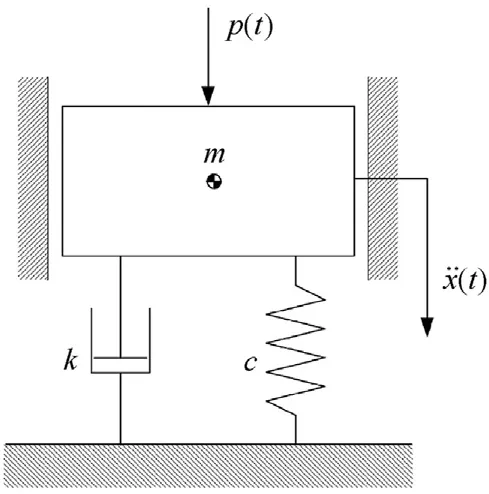
Fig.18.Schematic diagram of the dynamic model:c-Stiffness parameter;k-Damping parameter;m-Vibrating mass.
Knowing that the tested elements were positioned in such a manner that they could be considered to be in parallel connection,in the case of cylindrical samples the stiffness and specific damping can be calculated from the following relationship:
where,cz-artificial stiffness for the tested set of samples,kz-artificial damping for the tested set of samples.In the case of cubeshaped samples.
The parameters thus calculated are shown in Table 2.
The above experiments allowed the calculation of stiffness and damping for the investigated materials,and these parameters were subsequently used in further research on reducing the impact of external vibration on the directional control valve and the spool.The obtained results also indicate that for all types and dimensions of the elastomer elements,in the case when the longitudinal axis of the sample was parallel to the movement direction of the vibrating mass,the tested elements showed higher values of damping and stiffness than in the case when the longitudinal axis was perpendicular to the load direction.Moreover,the elastomer elements made of the Ultraflex 64 ShA material have significantly lower damping and stiffness values in comparison with elastomer elements made of the Adipol 70 ShA material.In the case of cubeshaped samples,the values of damping and stiffness parameters were observed to decrease together with an increase in the sample thickness.
4.4.Application of elastomeric material in vibro-isolation
The experiment involved a series of tests in which the hydraulic DCV was mounted in a dedicated holder of the simulator table,with the space between the valve casing and the vibrating holder filled with sets of vibro-isolating elements in various configurations(Fig.19).The properties of these elements were experimentally determined and are shown in above.The DCV was excited with harmonic vibration of the simulator table at a frequency in the range from 10 to 100 Hz and at a known amplitude.

Fig.19.Schematic diagram of the flexible connection between the DCV and the surface: (a) Locations of the elastic elements;(b) Dynamic model of the elastic elements.
Various sets of elastomer cushions were secured to both sides of the holder.The isolation effectiveness for the vibrations transferred to the DCV was evaluated by calculating the relationship between the amplitude of the valve vibration acceleration (response) and the amplitude of the table vibration acceleration (excitation).
Five different sets of vibration isolators were used in the tests.The individual sets differed in the number of elastomer elements and in the direction of the load with respect to the longitudinal axis of the cylindrical samples.This combination resulted in sets with different artificial stiffness and artificial damping values.Set Nr.1 consisted of 8 cylindrical elastomeric elements (4 made of Adipol 70 ShA and 4 made of Ultraflex 64 ShA)loaded perpendicular to the long axis of the specimen.The length of the specimen was 16 mm,inner diameter 6 mm,outer diameter 16 mm.Set Nr.2 consisted of two rectangular elements made of micro-rubber,measuring 101 mm×26 mm×15 mm.Set Nr.3 consisted of 8 cylindrical elastomeric elements (4 made of Adipol 70 ShA and 4 made of Ultraflex 64 ShA)loaded along the long axis of the specimen,Set Nr.4 consisted of 8 cylindrical elastomeric elements(made of Ultraflex 64 ShA),four elements were loaded perpendicular to the long axis of the specimen,4 were loaded along the long axis of the specimen.Set Nr.5 consisted of 12 cylindrical elastomeric elements(6 made of Adipol 70 ShA and 6 made of Ultraflex 64 ShA),4 elements were loaded along the long axis,8 elements were loaded perpendicular to the long axis.The values of artificial stiffness and artificial damping of the differently configured cushion sets are shown in Fig.20.
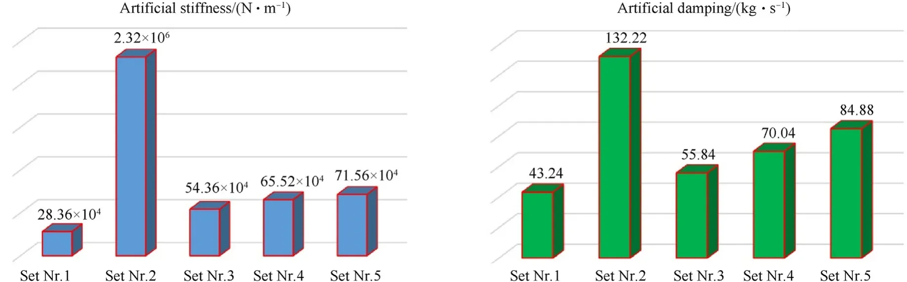
Fig.20.Values of artificial stiffness and artificial damping for the tested cushion sets.
Fig.21 shows the results plotted in the form of a cumulative graph representing the ratio of vibration acceleration amplitudes for the DCV and for the simulator table as a function of the excitation frequency.
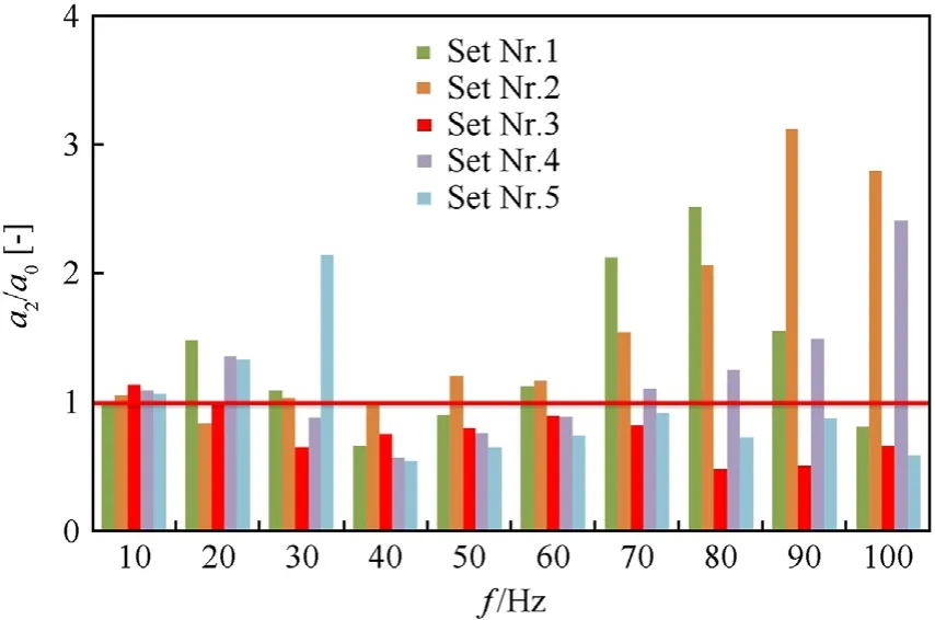
Fig.21.Vibro-isolation effectiveness for the DCV excited with surface vibration for different sets of elastic cushions: a2 -casing acceleration amplitude,a0-table acceleration amplitude.
The results presented above indicate that a system with appropriately selected cushion sets can provide effective vibroisolation in almost the entire range of the investigated frequencies.The most favourable features in the vibration isolation process are found in shim set No.3.For this shim set,the transfer function values are less than 1 over almost the entire range of vibration frequencies,as well as reaching the smallest values in comparison with the other shim sets.A reduction in the vibration on the DCV casing results in reduced external excitations acting on the spool through the set of centering springs and through the friction processes in the slide-sleeve pair.
5.Discussion
Another solution which can reduce the internal interactions due to mechanical vibration and which can be used in combination with the above-presented solution is to manipulate the valve design by introducing specially profiled flexible cushions (made for example of oil-resistant rubber)between the valve casing and the centering springs,as illustrated in Fig.22.The possibility to reduce spool vibration by introducing such a solution was verified experimentally.The DCV was mounted directly in the vibrating holder of the simulator table.The frequency range of vibrations on the simulator table was from 10 to 100 Hz.
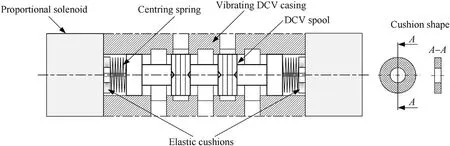
Fig.22.Cushions made of oil-resistant rubber installation inside the DCV casing.
The specific design of the tested DCV necessitated the use of cushions with an external diameter of 26 mm,an internal diameter of 22 mm and a height of 4 mm.Fig.23 shows a dynamic model of the spool inside the DCV casing.A spool having a mass m1is centered with springs of a known ratecs1each.Moreover,a dampingks1was assumed in the slide-sleeve pair,on each of its sides.
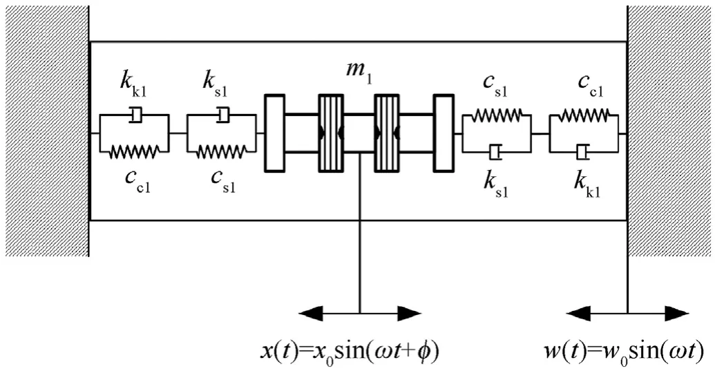
Fig.23.Dynamic model of the spool in the vibrating DCV casing.
The cushions are represented with the use of a model comprising linear elastic and dissipative elements connected in parallel (the so-called Kelvin-Voigt model),with one degree of freedom.For each of the two cushions,the stiffness was designated ascc1,and the damping -as kk1.
In the tested DCV,the rate of the centering spring wascs1=2900 N/m.The cushion stiffness wascc1=1.41×10⁶N/m.Therefore,the artificial stiffness for each of the spool sides,if considered in parallel connection,is 2894 N,while the artificial stiffness for both spool sides is 5788 N as in parallel connection.The artificial damping calculated analogically for one side was 8.66 kg,and for two sides of the spool it was 17.32 kg as in parallel connection.Fig.24 shows the results of the experimental tests,illustrated as a comparison of the effects of using cushions for the purpose of reducing spool vibration.
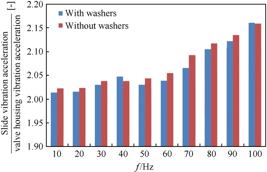
Fig.24.Relationship between the relative spool acceleration and the valve casing vibration acceleration as a function of the casing vibration frequency.
The analysis of the values of artificial stiffness on each side of the spool indicates that it is mainly influenced by the lower value,in this case by the stiffness of the spring.This fact is due to the parallel method of connecting the stiffnesses.The results presented in Fig.24 indicate that the solution does not cause a significant reduction of spool vibration.Therefore,the analysis should focus on the influence of cushion stiffness and damping modifications on the amplitude of spool vibration excited by the vibration of the casing.As far as DCVs controlled with proportional electromagnets are considered,the analysis should allow for the maximum forces offered by the proportional solenoid valves (they are typically approx.15-20 N[49,50]),as well as for the stroke required due to the design of the slide-sleeve pair (these are typically approx.4.5 mm for a proportional solenoid with adjustable stroke[49,50]).This fact limits the cushion stiffness,as the control force generated by the solenoid must be greater than the sum of the remaining forces,i.e.the friction forces in the slide-sleeve pair,the inertial force of the spool and the associated liquid,the force of the artificial rate of the centering springs and the cushions,or the hydrodynamic force.Therefore,elastic cushions should be introduced into the DCV in combination with springs of lower rate,adjusted to the control force of the proportional solenoid.
6.Conclusions
The research results address the problem of the possibility for minimizing the impact of external mechanical vibration on hydraulic valves used in the different military applications hydraulic drive systems.As indicated by the results of experimental tests,although it significantly reduces vibration acceleration in the isolation zone reaching 70%,the isolation solution in the form of springs causes an increase of vibration in the amplification zone of the DCV casing by almost 70%.This phenomenon will lead to pressure pulsations in the amplitude-frequency spectrum for frequency values of 10-20 Hz.And this will result in generating infrasound’s and mechanical vibration at corresponding frequencies.Another possible solution for reducing vibration on the DCV casing and consequently on the spool is to install the DCV on elastic cushions.The results of experiments indicate that the materials used in the cushions reduce vibration on both the casing and the spool.By using materials with appropriately selected elastic and dissipative properties,the effectiveness of vibro-isolation can be increased.
The above considerations also allow a conclusion that the vibration on the valve spool can be reduced by introducing a cushion,made of a material having high stiffness and damping,between the casing and the centering springs.In the case of single-stage electrically controlled (e.g.proportional) DCVs,such an approach may be subject to complications due to the maximum values of control forces offered by the proportional solenoids and to the required spool stroke.
The presented linear and non-linea mathematical models of vibro-isolation may serve to select materials having properties appropriate from the perspective of isolation effectiveness.As a result of introducing passive vibro-isolation,pressure pulsation reduction will lead to reductions of vibration on hydraulic systems and of noise emissions during operation,as well as to more steady operation of hydraulic receivers for minimizing the impact of external mechanical vibration on hydraulic valves what operate the actuators of military applications.
Declaration of competing interest
The authors declare that they have no known competing financial interests or personal relationships that could have appeared to influence the work reported in this paper.
杂志排行

Defence Technology的其它文章
- Interaction of water droplets with pyrolyzing coal particles and tablets
- Multifunctional characteristics of 3D printed polymer nanocomposites under monotonic and cyclic compression
- The concept of sUAS/DL-based system for detecting and classifying abandoned small firearms
- Modelling and predicting the dynamic response of an axially graded viscoelastic core sandwich beam
- Development of bimetallic spinel catalysts for low-temperature decomposition of ammonium dinitramide monopropellants
- Thrust characteristics of nano-carbon/Al/oxygenated salt nanothermites for micro-energetic applications