Autonomous UAV 3D trajectory optimization and transmission scheduling for sensor data collection on uneven terrains
2023-12-27AndreySvkinStishVermWeiNi
Andrey V.Svkin ,Stish C.Verm ,* ,Wei Ni
a School of Electrical Engineering and Telecommunications, University of New South Wales, Sydney, Australia
b Data61, CSIRO, Canberra, ACT, 2601, Australia
Keywords:Unmanned aerial system UAS Unmanned aerial vehicle UAV Wireless sensor networks UAS-Assisted data collection 3D trajectory optimization Data transmission scheduling
ABSTRACT This paper considers a time-constrained data collection problem from a network of ground sensors located on uneven terrain by an Unmanned Aerial Vehicle (UAV),a typical Unmanned Aerial System(UAS).The ground sensors harvest renewable energy and are equipped with batteries and data buffers.The ground sensor model takes into account sensor data buffer and battery limitations.An asymptotically globally optimal method of joint UAV 3D trajectory optimization and data transmission schedule is developed.The developed method maximizes the amount of data transmitted to the UAV without losses and too long delays and minimizes the propulsion energy of the UAV.The developed algorithm of optimal trajectory optimization and transmission scheduling is based on dynamic programming.Computer simulations demonstrate the effectiveness of the proposed algorithm.
1.Introduction
With their maneuverability and relatively low cost,Unmanned Aerial Vehicles (UAVs) provide effective means for many civilian applications,including support of wireless communication networks,environmental monitoring,emergency communications,disaster management,smart agriculture,and last mile delivery,see e.g.Refs.[1-4] and references therein.Furthermore,Unmanned Aerial Systems (UASs) consisting of UAVs,attracts more and more attention in various defence applications,where they are used to reduce risk to humans.These defence applications include but not limited to air combat,target tracking,unexploded ordnance detection,eavesdropping and counter-eavesdropping,see Refs.[5-12].Recent advances in wireless sensing technologies have resulted in the deployment of a large number of ground sensors for environmental monitoring,see e.g.Refs.[1,2].Data collection in wireless sensor networks can be challenging due to energy constraints or harsh environments.Data collection in wireless sensor networks is another area of UAV applications[1,2,4,13-17].A UAV is able to fly sufficiently close to a sensing device to increase data transmission rate and probability.A challenging and common in defence applications version of this problem is a case where a UAV is navigated over an uneven terrain,rather than broadly assumed flat terrain areas.Uneven terrains are geometrically complex grounds that are impossible to model with a sufficient accuracy by flat surfaces.On such uneven terrains,the Line-of-Sight (LoS) between the UAV and the transmitting sensors can be occlude by the terrain.Typical examples of uneven terrains include high density urban areas with big constructions and narrow roads.Another example is a precision agriculture scenario with a large number of sensing devices located in a mountain vineyard[1].Moreover,this problem is very important in defence applications,where the objective of the UAV is to covertly collect intelligence information from a ground sensor network located in a hilly area.
This paper addresses the problem of data collection from a wireless sensor network mounted on an uneven terrain by a UAV.The ground sensors harvest renewable energy from the environment to recharge their batteries and use the energy for sensing and data transmission.Moreover,the sensors measure the environment and buffer the measurements.The objective of the UAV is to collect data from the sensors by exploiting the LoS from the sensors.Moreover,the UAV is navigated to get as close to the sensors as possible to achieve high rate and high probability of successful data transmission.The paper [3] also considers a case of an uneven terrain,however,Ref.[3] studies a mobile-edge computing problem,not a data collection problem.Moreover,Ref.[3] does not consider data buffer and energy limitations for ground nodes,whereas the current paper takes all such limitations into account and addresses a case of ground sensors harvesting energy into batteries and equipped with buffers for measurements.
We propose a novel method for joint UAV path planning and data transmission,which maximizes a utility function describing the amount of transmitted data,the transmission time delays,and the propulsion energy of the UAV.We prove the asymptotic global optimality of the developed path planning method.More precisely,we prove that the constructed solution tends to the global maximum as some set of parameters tends to infinity.
The contribution and the novelty of this paper can be highlighted as follows.The paper studies the problem of joint UAV 3D trajectory optimization and transmission scheduling for data collection from wireless sensors located on a hilly terrain where the LoS between the UAV and the sensors is often interrupted.The UAV and the sensors can communicate only via LoS paths.The aim is to fly the UAV and schedule transmissions between the sensors and the UAV so that the UAV can establish LoS paths with the ground sensors sufficiently often to collect more data from the sensors.This is a difficult and original problem as other publications on this topic[1,2,4,13-17] do not properly investigate the challenge of frequent loss of the LoS between the UAV and the sensors due to a rough non-flat terrain.Moreover,the proposed algorithm is globally optimal and it is mathematically rigorously proved unlike many other published results in the area.
2.System model and problem statement
We consider the following UAS.There is a UAV flying in a 3D environment.The vector(x(t),y(t),z(t))gives the current 3D position of the UAV.The following common mathematical of the motion is used:
where v(·)∈[0,C1],ω(·)∈[-C2,C2]andu(·)∈[-C3,C3].Here μ(·)is the direction of the vehicle in a horizontal plane,v(·),ω(·)andu(·)are the inputs of the model representing linear horizontal,angular and vertical velocities of the UAV,respectively,C1,C2andC3are maximum limits of the corresponding control inputs.We also assume that for the UAV altitudez(t),the following inequalities must always hold:
with some given 0 <Zmin<Zmax.
The UAV is moving over an uneven terrain modelled by some a priori known altitude functione(x,y),wheree(x,y)is the altitude of the terrain point with 2D position(x,y).Notice that some points of the terrain can have altitudes aboveZminand evenZmax.The following constraint should hold for any trajectory(x(t),y(t),z(t)):
with some given ε >0.It is obvious that if Eq.(3) holds,a collision between the UAV and the terrain is impossible.
Furthermore,there areMground sensors,labelledj=1,…,M.Each sensor is equipped with an electric battery and harvests renewable energy from the environment.The harvested energy recharges the sensor's battery and is used to power sensing and data transmission.The function 0≤ej(t)≤Erepresents the battery state of sensorj,whereE>0 is a given constant.
Each sensor makes some measurements so that new sets of measurement data are collected at time instants 0,τ,2τ,3τ,…Where τ >0 is a given time.Moreover,these data are buffered by the sensors,and the data queue length of sensorjat timetisdj(t)∈{0,1,…,D},whereD>0 is a given positive integer.The new data obtained at the timekτ have to be dropped if the buffer is full,i.e.d(kτ)=D.Furthermore,at any time instanth0j+khwhereh0jandh>0 are given constants,j=1,…,M,k=0,1,2,…,the UAV can select the ground sensorjfor data transmission.Then,the sensor transmits one set of data,and the transmitted data is erased from the buffer,hence,dj(·) is decreased by 1.In other words,h determines the transmission rate of the sensors as each sensor can make one transmission at any time instanth0j+kh.The constantsh0jdetermine transmission time shifts of the sensors,as the sensors may not be synchronized and have differenth0jso they transmit at different times.Each sensor also harvests energy from the environment,charges its battery,and spends some amount of energy on measurements.So,if during a time interval [t1,t2] the sensor does not transmit data,the battery state is described by the equationej(t2)=min{ej(t1)+Ej(t2-t1),E}whereEj>0 is some given constant describing the energy harvesting rate,andEj>0 is some given constant describing the sensor's battery maximum state.In other words,without transmission,the state of the battery is increasing linearly over time but it cannot exceed the maximum battery stateE.Notice that the constantsEjmay be different for different ground sensors,as some of them can be located in shadow etc.,so they harvest less solar or some other renewable energy.Furthermore,if a ground sensorjtransmits a set of data at timeh0j+kh,its battery levelej(·) instantaneously decreases by the amountEtr,whereEtr>0 is some given constant describing the amount of energy needed for one transmission.
The UAV can select the sensor j for transmission at time h0j+khif the following conditions hold:
C1) LoS from the UAV to the sensor j is not blocked by some part of the terrain,see Fig.1.
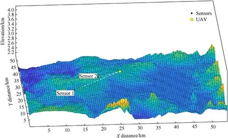
Fig.1.The LoS from the UAV to sensor 1 is blocked,the LoS from the UAV to sensor 2 is not blocked.
C2) The distancerj(h0j+kh) between the UAV and the sensor j satisfiesrj(h0j+kh) ≤R,whereR>0 is the communication radius of the sensor.
C3) The buffer is not empty,i.e.,dj(h0j+kh) >0.
C4) The battery has enough energy for transmission,i.e.ej(h0j+kh) ≥Etr.
Let 0 <P(r)≤1,r∈[ε,R]be a given decreasing function describing probability of successful transmission of data from a sensor to the UAV from the distancer.
The objective of the UAV is to navigate itself and schedule transmission times of the ground sensors to collect as many sensor data as possible.
Notice that in the current paper,we concentrate on LoS communication between the UAV and the ground sensors.LoS communication is preferred for UAV-sensor communication because it provides a strong,stable,and fast connection.Moreover,LoS becomes indispensable when high-frequency bands are utilized for communication,e.g.,in the upcoming six-generation(6G)mobile communication era where quasi-optical millimeter wave(mmWave),terahertz,and visual light communications (VLC) are expected to dominate.
On the other hand,LoS communication may not always be possible due to physical constraints,such as terrain or buildings,that can block the LoS between the UAV and the sensor.Our trajectory design philosophy is to design the trajectory of a UAV in such a way that at any point of the trajectory,there is a LoS between the UAV and its intended sensor.This design philosophy of maintaining effective LoS to the sensors is practical and rational.The reason is that the channel conditions of NLoS links can only be acquired via measurements on-the-spot or estimated empirically.The former (i.e.,on-the-spot channel measurement) violates the causality of the trajectory design,while the latter (i.e.,empirical modelling) is typically statistical and becomes inaccurate when it comes to a specific link.
We will control the system over the interval [t0,t0+T],wheret0>0 andT>0 are given.We assume that the UAV initial conditionz(t0) satisfies the constraints Eqs.(2) and (3).LetNj(t1,t2] be the amount of data from the sensorjreceived by the UAV over the time period(t1,t2].Furthermore,ε(·)denotes mathematical expectation of some random variable.Moreover,we introduce the functions γj(h0j+kh),j=1,...,Mas follows:γj(h0j+kh):=1 if the sensor j is selected by the UAV for transmission of data at timeh0j+kh,or γj(h0j+kh):=0 otherwise.In other words,the function γj(·)defines the transmission schedules for the ground sensorj.
Now,we introduce our optimal control problem:
where α >0 and β >0 are given constants,g (·,·,·)≥0 is a given function such that the integral term in Eq.(4) describes the propulsion energy of the UAV,and the maximum is taken over all possible UAV control inputs v(·),ω(·),u(·)and all possible sensor transmission schedules γj(·),j=1,...,M.The first term of Eq.(4)is included to achieve data transmission from as many ground sensors as possible,the second term is included to achieve a high value of the total amount of data transmission from all sensors,and the third term is included to achieve a low value of the energy expenditure of the UAV.Notice that the function g (·,·,·) is different for different types of UAVs.
Problem Statement.To jointly design UAV inputs v(·),ω(·),u(·)for the UAV Eq.(1)and sensor transmission schedules γj(·),j=1,...,M,that maximize the utility function Eq.(4) s.t.Eqs.(2),(3).
Remark 2.1.We assume that at any time t the UAV knows ej(t)and dj(t).Data and energy are obtained by the sensors at constant rates known to the UAV.Also,the UAV knows about all the transmissions(successful and unsuccessful) made by each sensor.Therefore,to derive ej(t) and dj(t) fort∈[t0,t0+T] the UAV needs to know just initial values ej(t0)and dj(t0).In practice,this can be achieved if the UAV operates during the interval [t0,t0+sT] wheres≥2 is some integer.Then during [t0,t0+T],the UAV just gets close to each sensor to get their current buffer and battery states,and then solves the stated problem during each interval[t0+rT,t0+(r+1)T],1=r<s.Another possibility is that in some scenarios as the sensors did not transmit beforet0,we can assume that their buffers and batteries have the maximum states att0.Also,it is assumed that the UAV knows the predetermined constantRin C2),sensor coordinates and the elevation functione(x,y) to determine LoS.
3.Path planning algorithm
We select a positive integerQand split the time interval [t0,t0+T]intoQsmaller subintervals with the length of δ:=each.We consider such control inputs vi(t),ωi(t),ui(t)that they change their values at timest0,t0+δ,…,t0+(Q-1)δ and keep fixed values over any smaller subinterval [t0+jδ,t0+(j+1)δ],0=j≤Q-1.We also select some integersq1>0,q2>0 andq3>0.These integers are the quantization levels of the control inputs.More precisely,introduce the following set of inputs:
The set of control inputs Eq.(5) can approximate any control
For all 0 <s<Sj,
input,including an input delivering global maximum if parametersQ,q1,q2andq3are large enough.
Now,we propose the following maximization algorithm.
MA1:Take all piecewise constant functions belonging to the class Eq.(5)that change their values att0,t0+δ,…,t0+(Q-1)δ,use these functions as the inputs of Eq.(1),check the constraints Eqs.(2),(3),and obtain the corresponding trajectories of the UAV over the interval [t0,t0+T] satisfying the constraints Eqs.(2),(3).
We buildW:=q1(2q2+1)(2q3+1)sets of constant control inputs from the class Eq.(5) for any smaller subinterval.Hence,as there areQsubintervals,we haveWQpossible system inputs.However,according toMA1,a branch of the tree of possible control inputs is ended every time when at least one of the constraints Eqs.(2),(3)is violated.Therefore,in practical scenarios,we usually have a much smaller number of possible inputs to check thanWQ.Notice thatWQdepends on algorithm parametersq1,q2,q3,Qand does not depend on the number of sensors M.As the computational procedure Eq.(6),Eq.(7) is a dynamic programming type procedure[18],with fixedq1,q2,q3,Q,the computational complexity ofMA1-MA4equalsO(M).
Proposition 3.1.There exists a set of control inputs and transmission schedules at which the global maximum in the optimization problem Eq.(4) s.t.Eqs.(4) (2),(3) is achieved.Whenq1→∞,q2→∞,q3→∞andQ→∞,the value of Eq.(4) delivered by the input and scheduling sequences constructed inMA1-MA4tends to the global maximum of this constrained optimization problem.
proof of Proposition 3.1.Indeed,the set of all possible control inputs for Eq.(1) such that the constraints Eqs.(2) and (3) hold satisfies the mathematical properties of the uniform continuousness and uniform boundedness [19].Hence,using the Arzela-Ascoli theorem [19],we can conclude that the global maximum in the constrained optimization problem Eq.(4) s.t.Eq.(2) is achieved.Furthermore,we can take control inputs v0(·),ω0(·),u0(·)and transmission schedulesthat give a value of Eq.(4)which is as close as we wish to the global maximum of Eq.(4).Such inputs may be approximated with any desired accuracy by piecewise constant inputs.Hence,we can build a sequence of inputs belonging to the class Eq.(5) that tends to v0(·),ω0(·),u0(·)if q1,q2,q3and Q approach to infinity.Hence,for this constructed input sequence and transmission schedulesthe value of the function Eq.(4)tends to the global maximum whenq1→∞,q2→∞,q3→∞andQ→∞.On the other hand,it follows from the dynamic programming principle(see e.g.[18]) that for any particular UAV path determined by particular inputs,the maximum of ε(Nj(t0,t0+T)is obtained from the transmission scheduling function γj(·)constructed byMA2and Eqs.(6)and (7).This implies that the value of Eq.(4) for the inputs and transmission schedules delivered by the algorithmMA1-MA4tends to the global maximum asq1→∞,q2→∞,q3→∞andQ→∞.This ends the proof of Proposition 3.1.
We point out that the proposed algorithm builds an almost optimal solution of the studied constrained optimization problem.More precisely,the obtained trajectories converge to the trajectory delivering the global optimum asq1,q2,q3andQtend to infinity.
4.Computer simulations
In the current section,the results of computer simulations for the Proposed Algorithm Approach (PAA) for joint UAV path planning and data transmission scheduling are presented.The proposed solution is compared with the state-of-the-art method of Ref.[20],referred to as Conventional Algorithm Approach (CAA).The simulations of the algorithms are performed in MATLAB.To mimic a real-world mountain terrain,terrain data from Yellowstone,USA has been used for the simulation,see Figs.2 and 3.This real-world terrain is generated with the help of the data collected by the United States Geological Survey [21].The environment consists of an uneven surface with five ground sensors.Each of them is shown as a black dot in Figs.2 and 3.The simulations run over 900 s,and start from the UAV initial position marked by yellow square in Figs.2 and 3.
As CAA is designed for the case of the UAV moving in a horizontal plane,to get a fair comparison with the proposed method,we consider the scenario withZmin=Zmaxwhere the UAV moves in the horizontal planez(t)=Zminwith the vertical speedu(t)=0.The values of the constants used for both simulations are given in Table 1.
The probability distribution function of successful transmission is defined asP(r)=The function may not accurately depict real-life transmission probability and is only used to test the proposed algorithm.Nevertheless,the function can be readily replaced by any other probability distribution function.The proposed algorithm only needs a monotonically decreasing function forP(r)and does not depend on it critically.We take the functiong(v,ω,u)=|v|+|ω|+|u|.To compare these two algorithms,we plot the values of the utility function Eq.(4) versus time for the UAV trajectories constructed by the CAA and the PAA in Fig.4.
CAA:This approach is based on designing a Dubins path that is a shortest smooth trajectory that is sufficiently close to all the sensors[20].The control input to the system is [v(t),ω(t),0],where the vertical velocity componentu(t)is always zero,so the UAV moves with a constant altitude.The linear speed of the UAV is constant.Using the brute force technique,the possible path value of (M+1)points on theXY-plane is calculated and compared.The solution gives the shortest path.However,this path does not satisfy a nonholonomic smoothness constraint.The Dubins curve is used to fit the non-holonomic constraints and generate a path on a horizontal plane for the UAV.It travels above the sensors in sequence{1,2,3,4,5},see Fig.2.Since the information about the state of the battery and data buffers’ states of the ground sensors is not taken into account while planning the trajectory,the UAV ends up visiting least-priority sensors first.It results in a smaller amount of data collected,and the value of the utility function is relatively low,see Fig.4.

Fig.2.Trajectories view I.

Fig.3.Trajectories view II.

Fig.4.Utility vunction.
PAA:We apply the proposed algorithm with parametersQ=9,q1=4,q2=5,C1=125 m/s,C2=10 rad/s andC3=10 m/s.Then a set of control inputs is calculated by Eq.(5).After checking the constraints Eqs.(2),(3) as required inMA1,the number of eligible control options drops significantly.We apply the control input produced by the optimization schemeMA4that gives the highest value for the utility function Eq.(4).The sequence of the sensors to be visited by the UAV is{4,3,2,1,5},and it is different from the CAA,see Figs.2 and 3.The amount of data and battery stored in sensor 4 is significantly higher when compared to other sensors.Unlike the CAA,the PAA prioritizes sensor 4 over other sensors,see Fig.2.Also,an advantage of the PAA is that it results in achieving the LoS between the UAV and the ground sensors more often than in the case of the CAA.The value of the utility function of the proposed algorithm is significantly higher that for the CAA.The PAA provides much better data collection from the ground sensors,see Fig.4.The proposed algorithm is more effective and efficient for maximizing data collection and minimizing energy expenditure when compared to the CAA.
5.Conclusions
A problem of joint 3D trajectory optimization and communication for a UAV flying over an uneven terrain was investigated.Under considered scenarios,the UAV navigates itself with the purpose to collect data from ground sensors mounted on an uneven terrain.A constructive and almost globally optimal method for joint trajectory optimization and sensor transmission scheduling was proposed and rigorously analysed.Computer simulations and comparisons with another advanced method demonstrated the performance of the presented method.There are several promising directions for future research in this area.One such a research direction is to extend the developed method to the case of several cooperating UAVs.In multi-UAV scenarios the issue of avoiding collisions between the UAVs should be addressed.Another challenge is to reduce computational complexity of an algorithm,especially for the multi-UAV case.It would be very interesting to obtain some not globally optimal but significantly less computationally expensive algorithm.Also,a promising direction of future research is to investigate scenarios in which sensor data collection is conducted by a team of cooperating UAVs and ground unmanned vehicles.
Declaration of competing interest
The authors declare that they have no known competing financial interests or personal relationships that could have appeared to influence the work reported in this paper.
Acknowledgments
This work received funding from the Australian Government,via Grant No.AUSMURIB000001 associated with ONR MURI Grant No.N00014-19-1-2571.
杂志排行

Defence Technology的其它文章
- Interaction of water droplets with pyrolyzing coal particles and tablets
- Multifunctional characteristics of 3D printed polymer nanocomposites under monotonic and cyclic compression
- The concept of sUAS/DL-based system for detecting and classifying abandoned small firearms
- Modelling and predicting the dynamic response of an axially graded viscoelastic core sandwich beam
- Development of bimetallic spinel catalysts for low-temperature decomposition of ammonium dinitramide monopropellants
- Thrust characteristics of nano-carbon/Al/oxygenated salt nanothermites for micro-energetic applications