Design of self-healing PEO-based protective layers containing in-situ grown LDH loaded with inhibitor on the MA8 magnesium alloy
2023-12-27GnedenkovSinebryukhovNomerovskiiFiloninaYuUstinovGnedenkov
A.S.Gnedenkov,S.L.Sinebryukhov,A.D.Nomerovskii,V.S.Filonina,A.Yu.Ustinov,S.V.Gnedenkov
Institute of Chemistry of FEB RAS, 159 Pr.100-letiya Vladivostoka, Vladivostok, 690022, Russia
Abstract The high corrosion rate of magnesium and its alloys in chloride-containing solution significantly reduces the potential of this material for diverse applications.Therefore,the formation of a smart protective coating was achieved in this work to prevent degradation of the MA8 magnesium alloy.A porous ceramic-like matrix was obtained on the material by plasma electrolytic oxidation (PEO).Further surface functionalization was performed using layered double hydroxides (LDH) served as nanocontainers for the corrosion inhibitor.Several methods of LDH intercalation with benzotriazole (BTA) were proposed.The composition and morphology of the formed coating were studied using SEM-EDX analysis,XRD,XPS,and Raman microspectroscopy.The corrosion behavior of the coated samples was evaluated using electrochemical impedance spectroscopy and potentiodynamic polarization.The corrosion rate was estimated using volumetry and gravimetry methods.The formed composite coating provides the Mg alloy with the lowest corrosion activity(|Z|f=0.1Hz=8.48·105 Ω·cm2,Ic=1.4·10-8 A/cm2, PH=0.21 mm/year) and improves the protective properties of the PEO-coated sample (|Z|f=0.1Hz=8.37·103 Ω·cm2, Ic=4.1·10-7 A/cm2, PH=0.31 mm/year).The realization of the self-healing effect of the inhibitor-containing LDH/PEO-coated system was studied using localized electrochemical methods (SVET and SIET) with two artificial defects on the surface.A mechanism involving three stages for the active corrosion protection of the alloy was proposed.These findings contribute to the follow-up work of developing modified LDH/PEObased structures that promote the Mg alloy with high corrosion resistance,superior electrochemical performance for applications in various fields of industry and medicine.
Keywords: Magnesium alloy;Plasma electrolytic oxidation;Layered double hydroxides;Corrosion inhibitor;Electrochemistry;Corrosion rate.
1.Introduction
Magnesium is a metal that is currently used in the various fields.It is applied in the automotive industry because it is lightweight and durable.Additionally,magnesium alloys have good recyclable properties,making them an excellent choice for green materials [1–3].
However,Mg and its alloys are limited because of poor corrosion and wear resistance [4–8].Active corrosion occurs,when magnesium alloys contact with water or other corrosion media [9].This negatively affects the mechanical properties of the material,causing thinning of the metal itself and an increase in the amount of oxides,that can lead to structural damage [10].
To inhibit the corrosion process,the metal is often coated with a protective layer to extend its exploitation period.These protective layers can be ceramic-like or contain polymeric materials.Various types of protective layers are used to protect magnesium and its alloys,such as coatings obtained using plasma electrolytic oxidation (PEO) [11–14],composite coatings [15–22] (including those formed using non-organic compounds [15,17,18] and organic polymers [19,23–25]),hydrophobic coatings [16,21,22],and coatings containing rare earth elements [26,27].Some of the pre-existing coating methods,such as chromate coatings [28,29] were quite toxic.Given the significant impact of human activities on the environment in modern times,it is crucial to use eco-friendly substances and coatings that will effectively protect the material without causing even minimal harm to the environment.
Currently,the development of smart protective coatings with corrosion inhibitors is an active subject of research [30–33].These coatings are designed to work when defects appear in the protective layer and the surface of the substrate becomes exposed.Once a defect is detected,inhibitors start to act,effectively suppressing the process of corrosion and healing the damaged area forming the protective film.This technology is particularly relevant for magnesium and its alloys,as microdefects may appear during operation due to plastic deformations.Smart coatings can help to heal these microdefects when exposed to corrosive media [10].
Smart coatings contain corrosion inhibitors that are released when the protective layer is damaged.Such coatings should contain structural fragments,or reservoirs,in which the inhibitor can be stored.
LDH (layered double hydroxides) are mixed hydroxides of Me2+and Me3+,which structure is composed of layers of double hydroxides with anions and water molecules in the interlayer space[34–37].The structure of LDH allows the insertion of various molecules into the interlayer space [36].Since the layers are not interconnected,the distance between them can be increased up to obtaining separate nanosheets [36,38–40].Therefore,LDHs can be used to intercalate corrosion inhibitors between layers (in the form of neutral molecules or anions) [41–44].For example,in [44] oleate-anion intercalation in the LDH structure was shown in XRD patterns since carbonate-anion is smaller than oleate-anion with long alkenyl group in structure.
Currently,the possibility of using this material is still being studied.For instance,works[45,46]showed that LDH,including those containing inhibitors,can be used as paint additives.The lack of the LDH formed directly on the metal surface[41,47] is its poor adhesive properties,that cannot significantly increase the lifetime of the material due to the defects that will be appeared during the exploitation period.LDH obtained on the surface of PEO-coatings can be reliably fixed on the surface and in the pores of the protective layer,due to its developed surface,and provide layered double hydroxides with direct contact with the coating to be healed when the material is damaged.However,to form the LDH structure on the PEO-coating surface is the challenging task.Therefore,there are few studies dealt with the formation of LDH directly on the PEO-layer [34,40,48].In [49,50] the authors used the PEO method to form protective layers on magnesium alloys and subsequently applied hydrothermal treatment.In[51],the study shows the formation of LDH layer on a PEOcoating formed on aluminum alloy,using conditions similar to hydrothermal ones (95◦C).The researchers successfully achieved an LDH layer with a thickness of 5 μm on the PEO-coating,followed by the intercalation of inorganic anions.However,these studies do not contain information about the mechanism of self-healing effect of these coatings.Moreover,it is not feasible to produce LDH layers on the surface of the thick PEO-coating,which has a thickness of approximately 20 μm,using hydrothermal method [49–51].In the work [51] the authors showed the negative effect of the increase in PEO-layer thickness on the quality of LDH structure formation on the PEO-coated surface using the hydrothermal method.The inapplicability of the hydrothermal method of LDH formation on the surface of thick coatings is related to generation of stresses caused by thermal expansion,which ultimately resulting in the deterioration of the PEO-layer.
When this was done, at a given signal, they began to perform their music together: the donkey brayed9, the hound barked, the cat mewed, and the cock crowed; then they burst through the window into the room, so that the glass clattered10! At this horrible din11, the robbers sprang up, thinking no otherwise than that a ghost had come in, and fled in a great fright out into the forest. The four companions now sat down at the table, well content with what was left, and ate as if they were going to fast for a month.
One of the challenging task in the formation of the self-healing coating is the choice of the appropriate corrosion inhibitor [22,52–56].Numerous inhibitors were investigated in the field of corrosion protection,such as rare earth elements [57–59],2-mercaptobenzothiazole [59,60],8-hydroxyquinoline [19,59],etc.However,many inhibitors,including eco-friendly ones,have not been thoroughly studied and deserve further investigation by researchers.Benzotriazole (BTA) is actively applied as a corrosion inhibitor for copper,aluminum,and magnesium alloys [61–64].Benzotriazole has demonstrated its effectiveness in protecting these metals and alloys by facilitating the formation of complex compounds at the defect sites,thereby inhibiting the corrosion process.BTA is also used in formation of the thick and compact anodizing films [61].This inhibitor is also applied in the formation of smart coatings with active corrosion protection [65–67].
This work is aimed at obtaining LDH on a ceramic-like PEO-coating (with 20 μm thickness) with subsequent functionalization of the protective layer.Various methods of LDH intercalation with a corrosion inhibitor are presented,using benzotriazole as an example,and the effectiveness of these methods for the formation of smart coatings is compared.The self-healing effect of these smart coatings in the presence of artificial defects was confirmed.The main objective of this study is to form the smart green composite coating on the magnesium alloy surface to expand its practical application as a functional and constructional material in such fields as automobile,aircraft industries and implant surgery.
2.Experimental
2.1.Coating formation procedure
Samples with the size of 20×20×2 mm made of MA8 magnesium alloy were used as substrates for this study.The specimens were preliminarily processed using sand paper with a grit size of P320 on a grinding machine,followed by washing with isopropyl alcohol and air-drying.
Four types of coatings were formed on the MA8 magnesium alloy substrate: base PEO-coating (PEO),PEO-coating containing LDH (PEO-LDH),PEO-coating containing LDH and treated with the inhibitor benzotriazole (PEO-LDH-BTA,where the LDH formation and impregnation with inhibitor realized in series) and PEO-coating containing LDH with the inhibitor (PEO-LDH(BTA),where the LDH formation and impregnation with inhibitor was done at once).The detailed procedure of coating formation is presented below.
2.1.1.Base PEO-coating formation
Then, after a hasty breakfast, he went to gather Beauty s rose, and mounted his horse, which carried him off so swiftly that in an instant he had lost sight of the palace, and he was still wrapped in gloomy thoughts when it stopped before the door of the cottage
PEO treatment of the Mg alloy samples was carried out in the electrolyte containing 15 g L–1Na2SiO3·5H2O (99.5 %purity,NevaReaktiv,Russia) and 5 g L–1NaF (99.5 % purity,NevaReaktiv,Russia) in the bipolar mode.The pH and conductivity of the electrolyte were 13.0 and 20.42 mS,respectively.The duration of the process was 600 s,during which the potential of the cathode phase was maintained at–30 V,while the potential of the anode phase increased linearly from 30 V to 300 V at a sweep rate 0.45 V s–1.The pulse duration was 30 ms with a 30 ms pause for each phase.
A mixture of 1.4 М MgCl2(99.8% purity,Sigma-Aldrich,Germany) solution (50 mL),0.7 М Al(NO3)3(99.9% purity,Sigma-Aldrich,Germany) solution (50 mL) and distilled water (100 mL) was heated to boiling.The initial pH of the solution was 1.3.Then,1 M NaOH solution (200 mL) was added dropwise to the boiling mixture with constant stirring,raising the pH of the solution to 12.4.The suspension was stirred for an additional 30 min after the complete addition of sodium hydroxide and then cooled.The precipitate was filtered,washed,and dried.This powder was designated as LDH-p.
Powder LDH-p (∼0.5 g) was added to 0.05 M benzotriazole water solution and constantly stirred for 24 h at room temperature to impregnate the LDH with benzotriazole.The powder was then filtered,washed with a small amount of distilled water,and dried.This sample was designated as LDHBTA-p.
2.1.3.PEO-LDH-BTA formation
The PEO-LDH samples were immersed in water solution of 0.05 M benzotriazole (BTA,99.9% purity,Sigma-Aldrich,Germany) for 24 h at room temperature.
7. Prudent4: While being prudent is usually a good thing, here it backfires. The eldest son is too prudent; he lacks compassion21 or charity. Because of this he fails what Maria Tater calls the test of compassion (284) that the old man offers him.In addition, the young man s response is rude and dismissive.Return to place in story.
When the prince had kissed his feet and received his blessing, he took from a casket a little collyrium of Solomon, which the Simurgh had given him, and which reveals the hidden things of earth, and rubbed it on his father s eyes
2.1.4.PEO-LDH(BTA)formation
A few minutes later he was back with his guitar and penned a few words of encouragement inside the guitar case. He asked us to please deliver the guitar and his cowboy hat to Miles at the hospital.
The PEO-coated samples were immersed in a solution containing 50 g L–1EDTA-Na,5 g L–1Al dissolved in 40 g L–1NaOH,and 0.05 M BTA.The samples were immersed in the solution and soaked for 48 h at 60◦C(hot solution treatment).
2.2.Powder synthesis procedure
Additionally,the powders of layered double hydroxides:LDH-p (MgAl-LDH powder without corrosion inhibitor),LDH-BTA-p (MgAl-LDH powder impregnated with benzotriazole;BTA was added after LDH synthesis),and LDH(BTA)-p (MgAl-LDH powder with benzotriazole;BTA was added during LDH synthesis) were prepared for investigation of phase composition of the formed materials.The detailed procedure of powder synthesis is presented below.
2.2.1.LDH-p synthesis
2.1.2.PEO-LDH formation
2.2.2.LDH-BTA-p synthesis
To form LDH on the PEO-layer,the PEO-coated samples were immersed in a solution containing 50 g L–1EDTA-Na(99.8%purity,Sigma-Aldrich,Germany)and 5 g L–1Al granules (99.9% purity,Sigma-Aldrich,Germany) that were previously dissolved in 40 g L–1NaOH (99.8% purity,Sigma-Aldrich,Germany).The samples were immersed in the solution (pH=13.5) and soaked for 48 h at 60◦C (hot solution treatment).
2.2.3.LDH(BTA)-p synthesis
The synthesis of LDH(BTA)-p was carried in the mixture of solutions described in 2.2.1 Section.For this synthesis,BTA was added to 200 mL of 1 M NaOH solution.The concentration of BTA in the solution was 0.05 M.
2.3.Test methods
whereVH(mL·cm–2·day–1) is the specific volume of evolved hydrogen per day of exposure of the sample.
The morphology of the coatings and the distribution of elements over their surface were studied by scanning electron microscopy (SEM) and energy-dispersive X-ray spectroscopy(EDX) using the EVO 40 (Carl Zeiss Group,Germany) with INCA X-act EDX analyzer (Oxford Instruments,UK).Crosssection of the PEO-LDH sample was prepared by cold mounting pouring the epoxy resin (ViaFix,Struers,Denmark) into a 25 mm diameter cup with specimen.The sample was then ground with silicon carbide (SiC) paper with a grit reduced from P600 to P1000 and polished using Tegramin-25 (Struers A/S,Denmark) with MD-Mol and MD-Nap disks according to method presented in [19].
2.3.2.XRD study
X-ray diffraction (XRD) analysis of the coatings was performed on a D8 Advance diffractometer (Bruker,USA) with CuKβradiation at room temperature.Measurements were carried out in the range of 2θ=4°–80° with a step of 0.02°.The values of the generator voltage and current were 40 kV and 40 mA,respectively.
X-ray diffractometer STOE STADI P(STOE&Cie GmbH,Germany) was used to obtain XRD data to characterize powder samples using the CuKβradiation at room temperature.Measurements were carried out in the range of 2θ=10°–80°with a step of 0.02°.
Grazing incidence X-ray diffraction(GIXRD)was obtained using RIGAKU SmartLab 9 kW (Rigaky Corporation,Tokyo,Japan).The Cu-Kαradiation was used to reveal the phase composition of the PEO-coated samples.The incidence beam angle was 0.1° and generator voltage and current were 45 kV and 200 mA,respectively.
2.3.3.XPS analysis
But despite these hesitations6, I found myself caught up in the joy and celebration of the moment, and I reached for the cookbook without another thought of the ring. My mom did love Irish things, and these were delicious. I opened the large coffee-table cookbook and turned to the pancake recipe. At once, something at the bottom of the page caught my eye... It sparkled! I gasped7 in utter amazement8! There, pressed into the pages of this book, was my diamond ring!
The aliphatic carbon (C 1 s) with a binding energy of 285.0 eV was used for spectrum calibration.The surface of specimens was Ar+-etched for 3 min at an energy of 5 keV to remove the contaminants and to provide the analysis of the inner layers of the formed coating.The ion etching resulted in coating thickness decrease by 3–5 nm.
2.3.4.Raman microspectroscopy
Raman microspectroscopy was employed to investigate the formed protective layers.Raman spectra of investigated samples and their optical images were obtained using a confocal Raman spectrometer alpha 500 (WITec,Ulm,Germany) using WITec Control/Project Plus 2.1 software.Raman spectra of the formed anticorrosion films were recorded between 100 cm-1and 1400 cm-1using 532 nm laser wavelength with a power of 20 mW.However,the analysis range was narrowed down to 200 cm-1to 1300 cm-1was chosen.To capture the sample’s image,an objective with 100× magnification (Zeiss EC “Epiplan” DIC,Germany) was utilized.The Raman spectra were collected from a 25 × 25 μm area,resulting in a data map comprising 50 × 50 sets.An integration time of 1 s was employed to obtain each Raman spectrum,and the average typical one is presented in this work.Background subtraction and baseline correction for the acquired Raman spectra were performed using of Origin software.The maps of LDH (1013–1113 cm-1) and BTA (732–832 cm-1) distribution on the specimen surface were designed for the samples using the shift range nearest the characteristic peak.
2.3.5.EIS measurements
Electrochemical impedance spectroscopy (EIS) was conducted using a Versastat MC electrochemical system (Princeton Applied Research,USA).The tests were carried out at room temperature in a three-electrode cell in a 3.5 wt.%NaCl solution.The surface area under investigation was equal to 1 cm2.The platinized niobium mesh was utilized as a counter electrode,while the silver chloride (Ag/AgCl) electrode,with a potential of 0.197 V relative to a normal hydrogen electrode,served as a reference electrode.Prior to the electrochemical measurements,the samples were kept in the electrolyte for 15 min to stabilize the electrode potential.The frequency range for the electrochemical impedance spectroscopy varied from 100 kHz to 100 mHz,employing a logarithmic sweep with 10 points per decade.The experiment was conducted over a 24 h.
2.3.6.Potentiodynamic polarization study
Potentiodynamic polarization tests were conducted with a sweep rate of 1 mV/s.The sample was polarized in the anodic direction within a potential range of– 0.25 V up to+0.7 V.The corrosion potential (Ec),corrosion current density (Ic),anodic (βa) and cathodic (βc) Tafel slops were determined by the Levenberg-Marquardt optimization algorithm (LEV)by fitting these parameters in Butler-Volmer Eq.(1).
This approach is suitable for characterizing the corrosion parameters of metals with a surface oxide layer,particularly magnesium and its alloys [9,14].The fitting potential range utilized was from -0.15 V to +0.15 V vs.Ec.Since anodic Tafel extrapolation is not always recommended for Mg alloys,particularly when PEO-coatings are applied,Icwas also calculated by means of intersection of the extrapolated cathodic linear region with a straight horizontal line drawn throughEc[68–70].The potentiodynamic polarization were carried out after 15 min exposure to 3.5% NaCl solution.Similar to EIS measurements,the counter and reference electrodes were utilized.To calculate the polarization resistance (Rp) according to Eq.(2) a separate experiment was conducted using linear polarization resistance technique[71,72].The specimens were polarized from (Ес-0.02) V to (Ес+0.02) V,with a sweep rate 0.167 mV s-1.
2.3.7.Scanning vibrating electrode and scanning ion-selective electrode techniques(SVET and SIET)
Local electrochemical behavior was investigated using the SVET/SIET system (Applicable Electronics,USA).To conduct local measurements,the area of the sample under study was isolated with beeswax.The exposed area was about 3 mm2and included two artificial defects made using CNC machine equipped with a 300 μm drill (Pi Di Precision,China).The detailed methodology of SVET/SIET tests was described in [8,73].SVET measurements were performed using a 10 μm platinum-iridium probe with a spherical tip coated with platinum black.Considering the surface roughness and heterogeneity of the obtained coatings,the SVET probe was located at a distance of 105 ± 5 μm above the surface with vibrations of 320 Hz (Z-axis direction) and 120 Hz (X-axis direction).The vibration amplitude was set at 20 μm.
For local SIET measurements,a scanning ion-selective(H+) microelectrode was used at a distance of 55 ± 5 μm above the surface.The ion-selective membrane column had a length of approximately 50–60 μm.The SIET electrode was calibrated in a NaCl solution with a fixed pH value,following the Nernst equation.Nernst slope was equal to 58.0 ± 0.6 mV·pH-1.The LV-4 software (ScienceWares,USA) was employed to carry out the scanning process.During quasi-simultaneous tests,the SVET probe was positioned on coordinates: 50 μm on the X axis,25 μm on the Y axis and 60 μm on the Z axis from the SIET electrode.This arrangement was implemented to prevent potential electrolyte mixing and the failure of the glass SIET electrode due to it’s multidirectional vibration.The electrolyte was refreshed every 4 h to stabilize the medium’s conductivity at 25.6 mS cm-1.The SIET electrode was replaced after every experiment to prevent contamination of the capillary electrode’s tip with corrosion products.The entire experiment had a duration of 24 h,and each scan consisted of 41 × 41 steps.
Male moved, the woman started to become very busy. Each morning to do a good job, she put bread, milk boiling hot, so hot Man eating breakfast. She was always behind with the keys in a Man locks put in jail, go to work before their own. Evening after work, women always hastily2 rushes home, only because the house keys from her run, she opened the door for a Man.
2.3.8.Corrosion rate evaluation
The corrosion rate was determined using volumetric and gravimetric methods.The long-term immersion corrosion test of the samples was conducted in the 3.5 wt.% NaCl solution during 7 days,following [74].
The volumetric corrosion ratePHwas calculated using Eq.(3):
2.3.1.Morphology and element distribution analysis
The gravimetric corrosion ratePWwas calculated using Eq.(4):
whereΔW(mg·cm–2·day–1) is the rate of mass loss per unit area of the sample.
3.Results and discussion
3.1.The coating morphology and composition
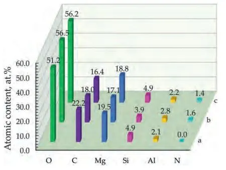
Fig.2.Elemental composition of the PEO-LDH (a),PEO-LDH-BTA (b) and PEO-LDH(BTA) (c) samples.
Fig.1 shows the distribution of elements over the surfaces of PEO-LDH-BTA and PEO-LDH(BTA)samples,as observed through EDX-mapping.The maps indicate a uniform distribution of Mg,Si,O,Al,C and N in the coatings.Mg,Si,and O are present in the base PEO-coating and remain after the hot solution treatment realized during LDH formation (Fig.2).Their respective contents in the coating of PEO-LDH sample are 19.5%,4.9% and 51.2%.The presence of 2–3 at.% Al in the coating is a result of hot solution treatment process.The presence of carbon in the coating can be attributed to the use of EDTA-Na during the synthesis of LDH.Nitrogen,as indicated by the elemental distribution maps (Fig.1),is presented in the samples after BTA-treatment,suggesting the impregnation of the coating with benzotriazole.The nitrogen content in this case is approximately 1.5 at.%.However,nitrogen is a light element that cannot be easily quantified by EDX and its small detected amount in the composition of the coating can be related with the error of this method.Therefore,the XPS and Raman microspectroscopy detailed analysis was applied in this work to confirm the presence of nitrogen-containing compounds.
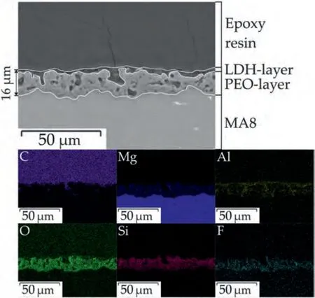
Fig.3.SEM image and EDX maps of the coating cross-section of PEO-LDH sample.

Fig.4.SEM images of PEO-LDH-BTA (a) and PEO-LDH(BTA) (b) samples.
Fig.3 depicts the cross-section image of PEO-LDH sample.Protective coating includes two sublayers: PEO-layer (including its porous and poreless parts)and LDH-layer.The size of PEO-coating pores varied in the range from 2 μm to 5 μm.The LDH-layer is presented on the surface and in porous part of the PEO-coating.The total tickness of the protective coating was 16±2 μm.The element distribution analysis showed that relative content of magnesium decreased in the following order: MA8 substrate,PEO-layer and LDH-layer.It was detected that oxygen,silicon and fluorine are mainly located in the PEO-coating.However,the aluminum is mainly presented in the composition of the LDH-layer.
When the kids came in, he took them for walks along the pier21 near their office. Often she went along and watched Eric, who was becoming a master of sign language, talk and laugh with her boys as no one else had before.
Based on the morphology of the formed crystallites(Fig.4) and previous LDH studies [16,31,49–51,75],it is assumed that the layer doubled hydroxide structures are presented.This assumption is supported by the XRD patterns of the samples (Fig.5a).The hydrotalcite peaks(Mg0.667Al0.333(OH)2(CO3)0.167(H2O)0.5),indicated by red triangles on the XRD patterns (peaks at approximately 11.6°,23.8°,and 34.8°),have low intensity due to the presence of LDH only on the surface.The high content of MgO and Mg2SiO4in the base PEO-coating,as well as a significant response from the Mg substrate were also shown using XRD.However,no benzotriazole peaks were detected on the XRD patterns.
The phase composition of the samples with protective coatings were additionally studied using grazing angle X-ray diffraction (GIXRD) analysis (Fig.5b).The obtained results show the same composition of the investigated specimens that was presented in Fig.5a.However,the peak,which is responsible for the Mg phase was not found using GIXRD.Mg signal from the substrate is presented on the XRD diagram in Fig.5a due to the low reflectivity of the PEO-coating.The GIXRD phase analysis indicated that the studied coatings did not contain the metallic magnesium in their composition.The GIXRD patterns show high intensity of the hydrotalcite peak (2θ≈12°,24° and 35°) as this method primarily investigates the top layers of the surface,where a significant portion of the LDH was detected.The analysis of the Fig.5b indicated that peak at 12°for PEO-LDH-BTA was more intensive among the other samples.It should be noted,that another hydrotalcite-like phase with other stoichiometry Mg0.833Al0.167(OH)2(CO3)0.083(H2O)0.75was also found using GIXRD (blue triangles in Fig.5b).Moreover,this phase was detected only for the samples with LDH structures intercalated with benzotriazole.
Since no benzotriazole peaks were observed on the XRD patterns of the coatings,it was necessary to determine whether BTA had been incorporated into the LDH structure.LDH powders similar to those formed in the coatings were prepared.Although there were differences in the synthesis process,the structure remained identical.XRD patterns (Fig.6)of LDH-p,LDH(BTA)-p and LDH-BTA-p were analyzed and the values ofd006parameter were calculated.The XRD diffraction patterns of LDHs powders show clear evidence of the LDH structure,distinguishing them from ordinary hydroxide or any other bulk or nanostructured material.The subsequent diffractions observed from the basal planes,specificallyd003=2d006=3d009,indicate the presence of well-packed brucite-like layers stacked in an ordered manner along the c-axis.These measurements provide information about the thickness of the brucite layer and the interlayer distance.Variations in LDH patterns are primarily observed in the d-spacing between successive (003) planes.
It is important to note that STOE STADI P has hardware limitations,when it comes to small angles,with a lower limit of 2θat 10°.Consequently,obtaining a peak for the (003)plane was not possible.The XRD patterns reveal compounds with rhombohedral symmetry with well-defined layered structures,as indicated by the presence of peaks corresponding to the (006) and (009) planes at 2θ≈23°,35°,respectively.For LDH(BTA)-p,the peak for (006) is located around 2θ≈22°,and it appears wider compared to the other samples.Furthermore,apart from the peak at 2θ≈35°,an additional peak corresponding to the (009) plane at 2θ≈32° was observed for LDH(BTA)-p.The appearance of this peak can be attributed to the intercalated LDH structure,as reported in the work [40].Moreover,the broader (006) plane peak indicates the incorporation of benzotriazole molecules into the LDH structure,resulting in an increased interplanar distance [34].
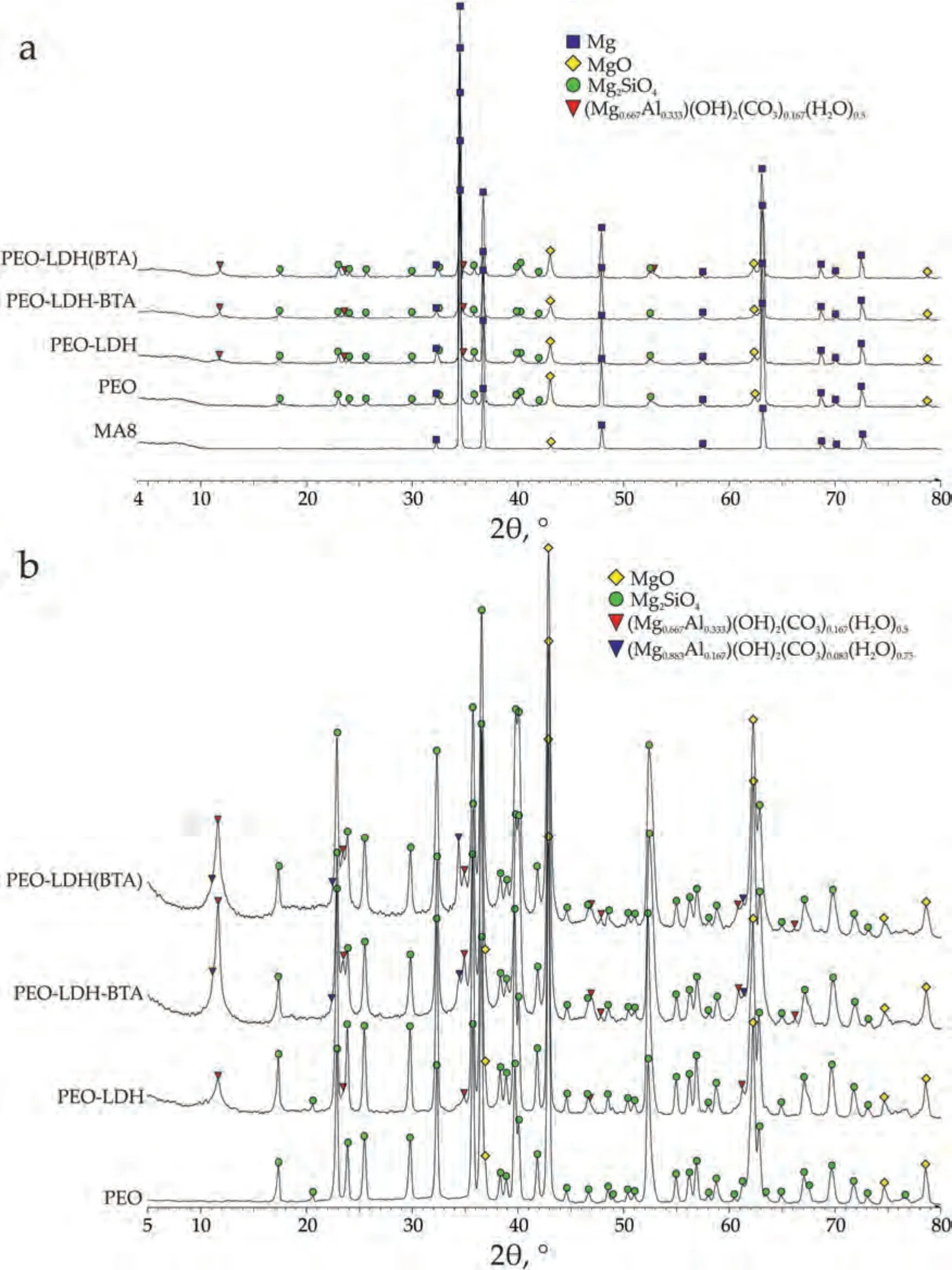
Fig.5.XRD (a) and GIXRD (b) patterns of MA8 alloy with different protective coatings.
LDH(BTA)-p exhibits two states: the intercalated hydrotalcite state and non-intercalated hydrotalcite state.Additional peaks detected at 2θ≈39°,47°,61°,and 62° correspond to the crystal planes (015),(018),(110),and (113) of LDH compounds,respectively,as reported in [76].LDH-p and LDHBTA-p display sharp,narrow,and symmetric reflections at low 2θvalues for the basal (006),and (009) planes.In contrast,the non-basal (015),and (018) planes exhibit asymmetric and broader reflections at higher 2θvalues.
Unfortunately,due to hardware limitations of the device in the region of small angles (the low limit of 2θis 10°),the values of thed003parameter could not be calculated.Nevertheless,d006parameter can be calculated from experimental data using Bragg’s law Eq.(5):
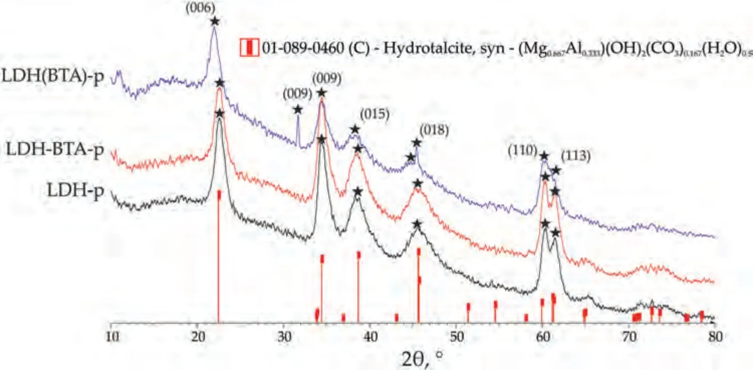
Fig.6.XRD patterns of LDH-p,LDH-BTA-p and LDH(BTA)-p powders.
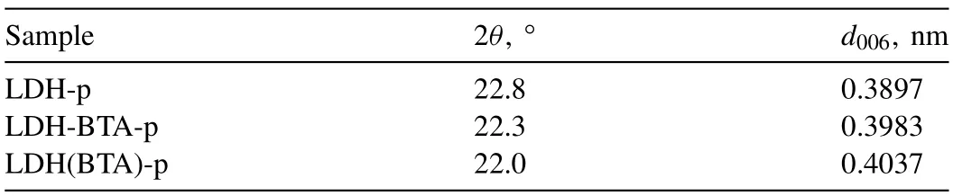
Table 1 2θ and d006 parameters obtained and calculated for powder samples.
wheredis a grating constant (the spacing between the planes in the atomic lattice);θis a glancing angle;nis an integer;λis a wavelength of X-rays.
Moreover,since thed006parameter is correlated with lattice parametercaccording to Eq.(6) [77],it was possible to estimate the increase in the interlayer distance at the benzotriazole intercalation within the LDH structure (Table 1).These results indicate that thed006increases in the following order:LDH-p/LDH-BTA-p/LDH(BTA)-p.It can also be assumed that the intercalation process of LDH powder and PEO-LDHBTA,PEO-LDH(BTA)samples occurs differently.In the case of the powder,the appearance of the hydrotalcite peaks remains unchanged and only a part of the reflections (006) and(009) shifting in the region of small angles.However,in the case of the coatings,the formation of another hydrotalcite-like phase with a different stoichiometry was observed.
But the maiden had determined to free her brothers even if it should cost her her life.31 She left the hut, went into the forest, climbed a tree, and spent the night there.32 The next morning she went out, collected star-flowers,33 and began to sew.34 She could speak to no one, and she had no wish to laugh, so she sat there, looking only at her work.
Our performance is based on classical ballet but it s still very accessible, says Nilas Martins, the ballet company s lead dancer. It s a fun performance. It s like watching fireworks, he continues.
X-ray photoelectron spectroscopy was used to determinate of composition of the obtained coatings.Protective layers of the PEO,PEO-LDH,PEO-LDH-BTA and PEO-LDH(BTA)samples were studied.Figs.7–10 display the survey and high resolution spectra for C and O (for PEO and PEO-LDH) and for C,N and О (for PEO-LDH(BTA) and PEO-LDH-BTA).All peaks,including Auger peaks,are indicated on the survey spectra.According to the calculated results presented in Table 2,all coatings contain Na (in the Na+state),Mg (in the Mg2+state) and O (as SiOx,AlOx,COx,-OH or MgO).The sodium cation content is equal to 1.6–3.3 at.% for the PEO sample and about 0.3–0.5 at.% for others.The presence of sodium and fluoride in the coatings is attributed to the sodium salts (sodium metasilicate and sodium flouride)present in the electrolyte used for the PEO process.Silicon is presented in the coating in the Mg2SiO4,which is supported by XRD data.It should be noted that sodium,fluoride,and silicon content decreased after LDH formation on the PEOtreated surface.There is a significant amount of magnesium in all coatings since it is the primary metal in the alloy.Additionally,the coatings exhibit a high amount of oxygen.The atomic percentage of oxygen in oxide MgO is almost equal in all coatings,except for the PEO-LDH(BTA) sample,where the oxygen content is 13.0 at.% before etching.The amount of oxygen in the oxides and hydrooxide increases from 21.3 to 29.8 at.% for PEO and PEO-LDH,respectively.This indicates the formation of LDH in the coatings,as this structure contain a significant quantity of carbonate and hydroxide groups.Aluminum (in the form of Al3+) was detected on the surface of LDH-containing samples: PEO-LDH,PEOLDH(BTA),and PEO-LDH-BTA,with a content ranging from 6.8 to 13.0 at.%.Nitrogen in the form of pyrrol (C-NH) and pyridine (-N=N+=N-) types was detected only for coating impregnated with BTA.It content in PEO-LDH(BTA)slightly decreases from 2.3 to 1.8 at.% with depth,suggesting the presence of the most part of the inhibitor on the surface.Conversely,for PEO-LDH-BTA the nitrogen content increases from 0.6 to 2.1 at.% with depth,indicating that benzotriazole is not only presented on the surface but also incorporated into the LDH crystallites at deeper levels.Presence of carbon (in the form of C–C,O-C=O,C–O–C) on the coating is due to surface contamination.Its content significantly decrease after the surface etching.However,the presence of carbon in the form of CO32-and M-C (M stands for the metal) was detected for the LDH-contaning samples.This result is due to the hydrotalcite structure formation.The presence of carbon in the form of C-N for the BTA-containing sample confirms the successful LDH impregnation with the inhibitor.
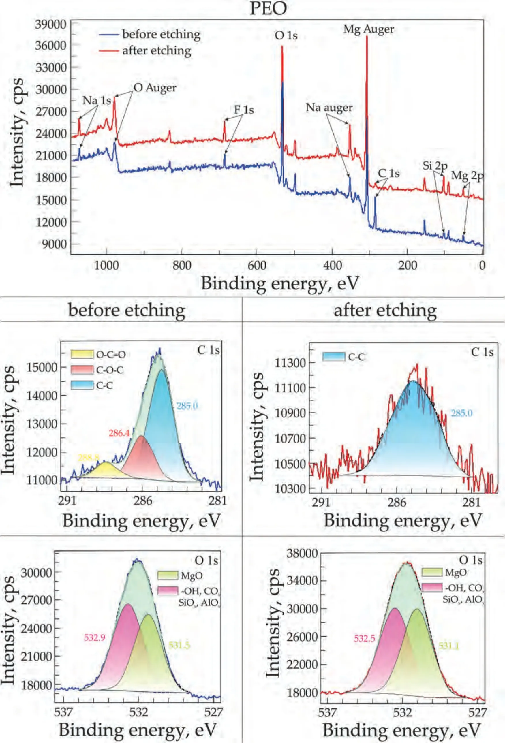
Fig.7.XPS survey and high resolution spectra of C 1 s and O 1 s for the PEO sample.

Fig.8.XPS survey and high resolution spectra of C 1 s and O 1 s for PEO-LDH sample.
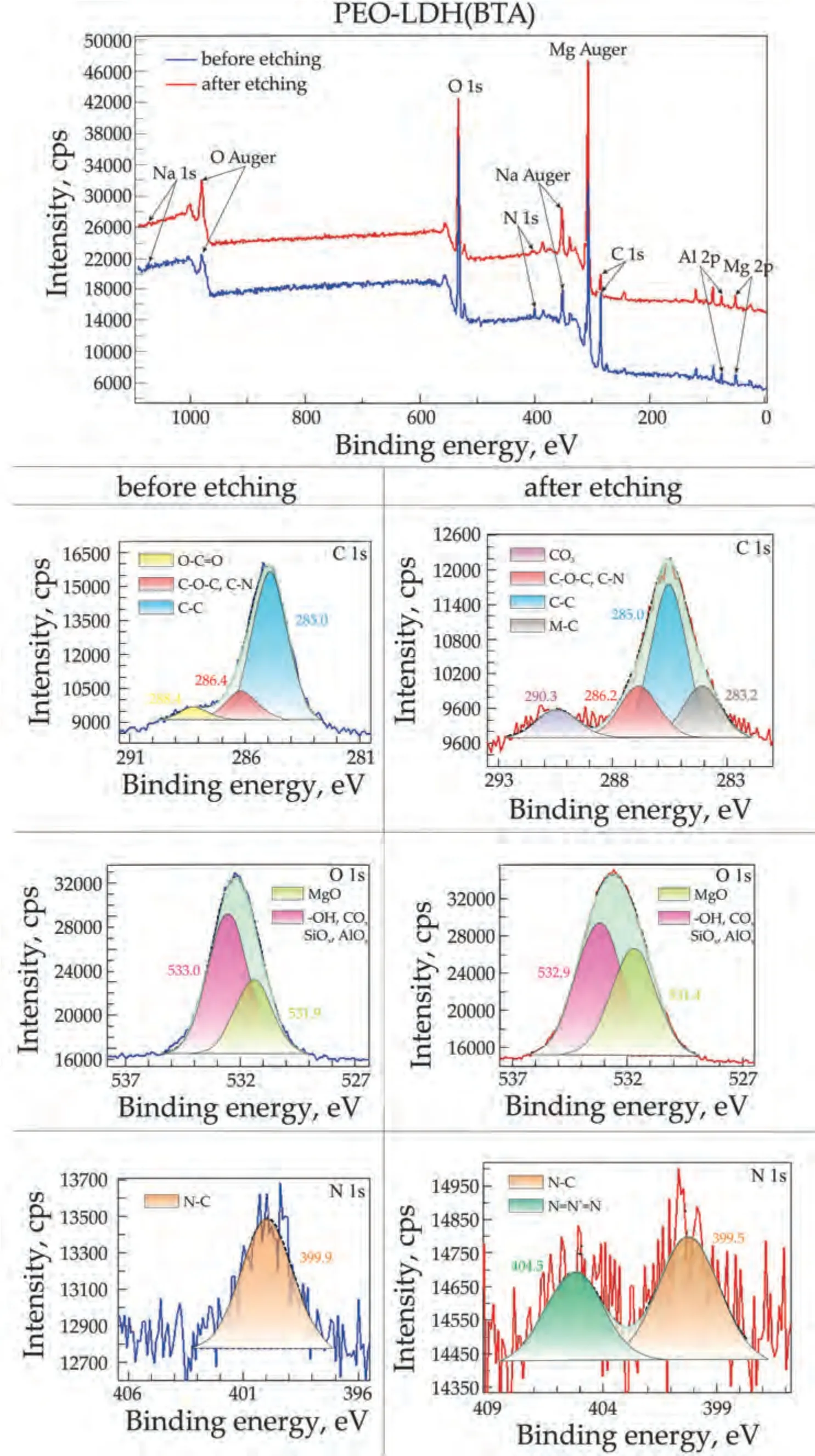
Fig.10.XPS survey and high resolution spectra of C 1 s,O 1 s,and N 1 s for PEO-LDH(BTA) sample.
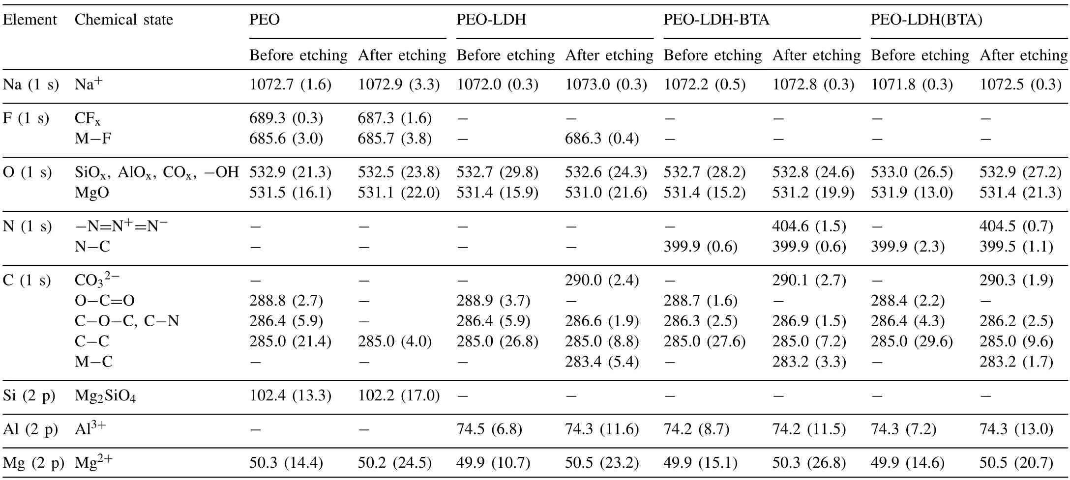
Table 2 Binding energy (eV) and elemental composition (at.% in parentheses) of the studied coatings.
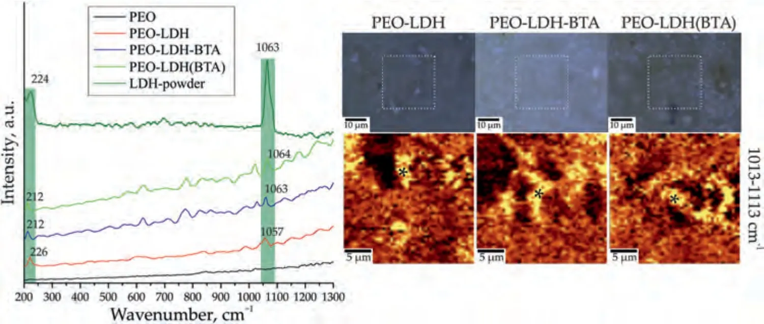
Fig.11.Raman spectra,optical images and maps of the LDH distribution (2D map was designed using a filter in the spectral range of 1013–1113 cm–1 corresponding to the characteristic peak for carbonate anion in LDH) for PEO-LDH,PEO-LDH-BTA and PEO-LDH(BTA).Raman spectra for PEO and LDH-powder are presented for comparison.
Confocal Raman microspectroscopy was used to show the distribution of LDH and benzotriazole on the surface of the coatings (Figs.11,12).The Raman spectrum of LDHp (Fig.11) displays two characteristic peaks of this structure.The peak at 234 cm–1is associated with Me–O stretching bonds,and the high intensity peak at 1063 cm–1corresponds to the CO32–symmetric stretching bonds.
Analysis of the spectrum of benzotriazole powder indicates the characteristic bands of this inhibitor (Fig.12).An intense peak at 782 cm–1corresponds to the “breathing” vibrations of the C=C bonds of the benzene ring.Peaks at 1006 cm–1and 1022 cm–1are associated with bending vibrations of bonds,which are caused by stretching of C=C skeletal bonds in the benzene ring,as well asδ(CH)) [78,79].Peaks at 1095 cm–1and 1126 cm–1refer to bending vibrationsδ(NH) andδ(СH),respectively.The narrow peak at 1209 cm–1is responsible for the combination of asymmetric stretching vibrationsν(N–N–N) and bending vibrationsδ(NH).The peak at 632 cm–1describes torsional vibrations of bonds in the triazole ring[78–80].
Yes, she said. It s a fine blanket. She felt the wool and repeated in surprise, A fine blanket—I ll say it is! She turned to Dad and said to him coldly, That blanket really cost something.
To investigate the distribution of LDH (Fig.11) and BTA(Fig.12) on the surface,a filter was used in the region of the prominent characteristic peaks for LDH (1013–1113) cm-1and BTA (732–832) cm-1.The distribution maps obtained reveal a widespread presence of these components across the surface with only a few areas indicating a low concentration.Spectra were captured at the marked points for further analysis.The spectra show the presence of LDH,as evidenced by a strong peak at 1063 cm-1,corresponding to the symmetric stretching bonds of CO32–,and a peak at 224 cm-1,representing the Me–O stretching bonds.Additionally,the presence of benzotriazole on the surface of the PEO-LDH-BTA and PEOLDH(BTA) samples is observed,with distinct peaks at 632,782 and 1022 cm-1.These peaks are associated with torsional vibrations of bonds in the triazole ring,“breathing” vibrations of the C=C bonds in the benzene ring and stretching of C=C skeletal bonds in the benzene ring,respectively.
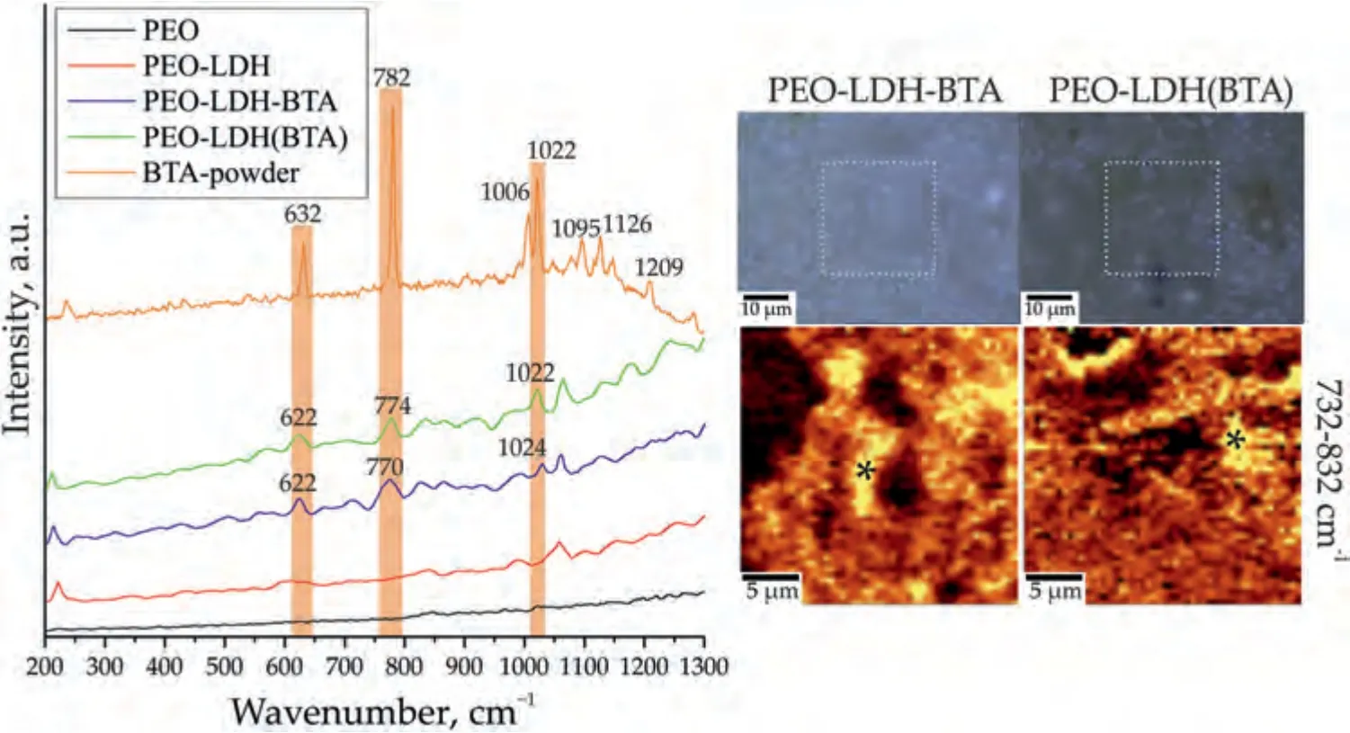
Fig.12.Raman spectra,optical images and maps of the BTA distribution (2D map was designed using a filter in the spectral range of 732–832 cm–1 corresponding to the characteristic peak for benzotriazole) for PEO-LDH-BTA and PEO-LDH(BTA).Raman spectra for PEO,PEO-LDH,and BTA-powder are presented for comparison.
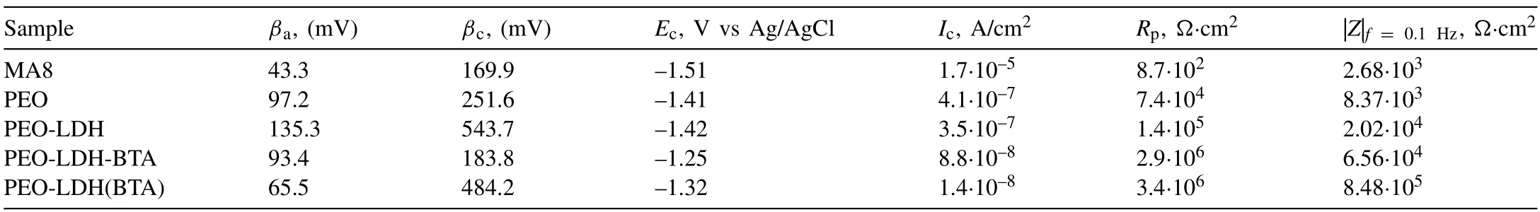
Table 3 The calculated corrosion parameters for the studied samples after 1-hour exposure to 3.5% NaCl solution.PDP curves were analyzed using LEV algorithm.
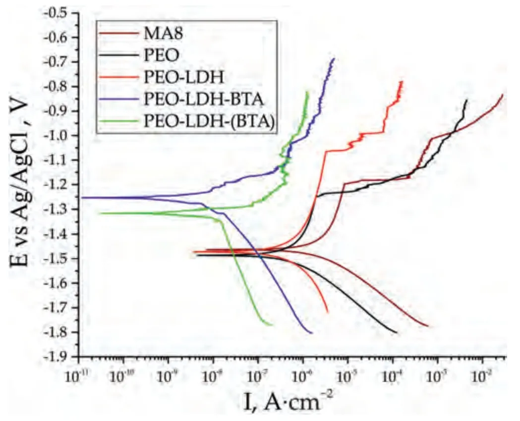
Fig.13.PDP curves for the samples after 1 h immersion in 3.5% NaCl solution.
3.2.The assessment of the protective properties
The potentiodynamic polarization technique was applied to assess the protective properties of the coatings (Fig.13 and Table 3).Based on the data obtained using LEV algorithm,the corrosion current density (Ic) decreased by 4 and29 times for the coatings containing LDH impregnated with BTA through the two-step (PEO-LDH-BTA) and one-step(PEO-LDH(BTA)) process,respectively,as compared to the base PEO-layer.Furthermore,the polarization resistance (Rp)also shows the highest value for the PEO-LDH(BTA) sample(Table 3).The electrochemical parameters were also calculated using cathodic extrapolation method (Table 4).The obtained results are in agreement with ones presented in Table 3.The lowest value of the corrosion current density was also regi
杂志排行

Journal of Magnesium and Alloys的其它文章
- Improvements in mechanical,corrosion,and biocompatibility properties of Mg–Zr–Sr–Dy alloys via extrusion for biodegradable implant applications
- Ultrasonic solidification mechanism and optimized application performances of ternary Mg71.5Zn26.1Y2.4 alloy
- Superplastic behavior of a fine-grained Mg-Gd-Y-Ag alloy processed by equal channel angular pressing
- GO/MgO/Mg interface mediated strengthening and electromagnetic interference shielding in AZ31 composite
- Experimental and theoretical studies on two-dimensional vanadium carbide hybrid nanomaterials derived from V4AlC3 as excellent catalyst for MgH2
- Electrochemical synthesis of boron-containing coatings on Mg alloy for thermal neutron shielding