Electrochemical synthesis of boron-containing coatings on Mg alloy for thermal neutron shielding
2023-12-27NadaraiaSuchkovMarkinImshinetskiyIvannikovMashtalyarYuUstinovSinebryukhovGnedenkov
K.V.Nadaraia,S.N.Suchkov,N.S.Markin,I.M.Imshinetskiy,S.I.Ivannikov,D.V.Mashtalyar,A.Yu.Ustinov,S.L.Sinebryukhov,S.V.Gnedenkov
Institute of Chemistry FEB RAS, 159 Pr.100-Letiya Vladivostoka, Vladivostok 690022, Russia
Abstract The work provides the results of the one-step formation of boron-containing coatings on an Mg–Mn–Ce alloy by plasma electrolytic oxidation.The results of studies of the composition,structure and morphology of heteroxide coatings are presented.It was established that the boron is contained in the coating mainly in the form of B or B2O3.The introduction of B changes the color of coatings,and also helps to increase their porosity.The method of determining the full cross section of the interaction of thermal neutron absorption efficiency by samples material using the installation of neutron-activation analysis based on 252Cf was developed.It was shown that the introduction of boron into the formed coatings allows to increase the macroscopic cross-section of the interaction of samples with thermal neutrons by 3.8 times.This effect opens the potential for the use of synthesized material in the field of nuclear technologies and aerospace industry.
Keywords: Plasma electrolytic oxidation;Boron;Neutron capture;Neutron shielding;Protective coatings.
1.Introduction
Formed by the plasma electrolytic oxidation (PEO) coatings on alloys of various metals are used in many modern industries [1–4].Thus,PEO coatings are already used in the automotive industry,aircraft industry,shipbuilding,as well as in surgery and dentistry [5].Such surfaces make it possible to impart various properties to metals: resistance to corrosion and wear,hydrophobicity,electrical insulating properties,biocompatibility,photocatalytic properties,and much more[6–8].One of the main advantages of PEO is the possibility of modifying the composition and structure of coatings by oxidizing the material with the inclusion of electrolyte components.Today,the trend in the development of PEO technology is addition of various inorganic particles to the composition of the electrolyte,which,through the flow of plasma discharges,can be introduced into the surface layer and contribute to additional functionality [9–16].
There are many works devoted to the introduction of micro-and nano-sized particles into the structure of PEO coatings.Thus,it was shown in [17–19] that the addition of nanosized zirconium dioxide and silicon improves the corrosion properties of the material,and the introduction of aluminum oxide or titanium nitride can increase the resistance of coatings to mechanical wear by an order of magnitude in comparison with PEO layers without particles [16,20,21].Zinc oxide particles can impart an antibacterial effect as well as improve corrosion properties,and the inclusion of hydroxyapatite in the composition of coatings increases osseointegration and biocompatibility of the material with bone tissue[10,19,22–24].In turn,particles of titanium dioxide and zinc can contribute to imparting photocatalytic properties to the surface of PEO coatings [2,16,25].
Thus,we can conclude that,depending on the task,it is possible to select the necessary doping components to impart certain properties.In turn,boron,as well as its compounds,seems promising for incorporation into the PEO coatings [26–29].Boron has broad functionality and is used for various purposes [30–35].In the form of fibers,B serves as a strengthening agent for many composite materials;it is used in electronics as an acceptor additive to change the type of silicon conductivity [36–39].In metallurgy,boron is used as a microalloying element,which significantly increases the hardenability of steels [40].In the field of nuclear technology,B as part of coatings can be used to provide radiation protection against neutron radiation,since it has the largest thermal neutron capture cross section among light and widespread elements.The cross section for the capture of thermal neutrons by the10B isotope (isotopic abundance is 19.8%) in the reaction10B(n,α)6Li is 3837 b [41,42].Thus,coatings containing even small amounts of B can absorb a significant part of the thermal neutron flux.
An analysis of the recent works shows that magnesiumbased alloys are promising materials for the formation of PEO coatings on their surfaces [43].Having such an important feature as a combination of high strength with low specific density,Mg alloys are promising as structural materials [44–46].The widespread use of Mg is hindered by its high thermodynamic activity and low resistance of the natural oxide film that forms on it in air [47,48].The developed electrolytic systems and PEO modes in silicate electrolytes made it possible to impart high strength and anticorrosion properties to the surface of Mg alloys,thereby increasing the possibility of their application in industry [6,8,14,49–55].
Magnesium,its alloys,and compounds under the conditions of gas-cooled reactors of low parameters demonstrate relatively good radiation resistance.No significant radiation effects (swelling,radiation creep,changes in strength and plasticity) are observed in these materials up to a neutron fluence of 1021cm–2.By modifying the surface of Mg alloys by plasma electrolytic oxidation with the incorporation of B,it is possible to achieve an increase in radiation resistance(together with corrosion and mechanical resistance).This,in turn,will significantly increase the service life of such materials.
Optimization of electrolytic systems and electric current modes of the PEO process will allow developing a method for the formation of boron-containing coatings on Mg alloys.Such coatings can have several significant properties for the surface of the alloy,providing them with additional functionality.In accordance with the above applications of boron and its compounds,it can be concluded that the developed boron-containing PEO coatings can be used as a material for physical protection against neutron radiation.
Thus,presented study is devoted to the formation of boroncontaining coatings on Mg alloy with the ability of neutron shielding.To achieve this goal,we have developed a mode and electrolyte for PEO for incorporation of boron particles into the surface layer on a Mg alloy.The composition and structure of the coatings were also studied in detail.The form in which boron was introduced into the PEO layer was established.And the absorption of neutron radiation by coatings were studied.To the best of the authors knowledge such studies were conducted for the first time.
2.Materials and methods
2.1.Samples preparation
Rectangular plates 20×20×1.5 mm3of Mg alloy were used as samples (Mg–Mn–Ce system: 1.3–2.2 wt.% Mn;0.15–0.35 wt.% Ce;Mg to balance).To standardize the surface,the samples were processed with SiC paper with a decrease in the grain size of the abrasive material to 15 μm.Then,the samples were additionally polished with aluminum oxide paper with a grain size of up to 3 μm.After polishing,the samples were washed with deionized water,degreased with alcohol using an RK 31 ultrasonic bath (Bandelin Electronic,Germany),and dried in air.
2.2.Electrolyte preparation
Plasma electrolytic oxidation of Mg alloy was carried out in an electrolyte containing 15 g L–1Na2SiO3·5H2O and 5 g L–1NaF (both Sigma-Aldrich,USA,analytical grade).This electrolyte makes it possible to form heterooxide structures on the surface of a magnesium alloy,which significantly improve the initial physicochemical (corrosion and mechanical) characteristics of the materials surface [56].To form boron-containing PEO coatings,5 g L–1of B powder (High purity substances,Russia,analytical grade) was added to this electrolyte.Boron powder consists of 2 phases: boric acid (sassolite) and crystalline boron in the rhombohedralβ-modification (Fig.1a).
The admixture of boric acid in the powder is explained by the process of obtaining boron powder.By the Moissans method (metallothermic method) boron is reduced from boric anhydride B2O3(after the purification process,the proportion of pure B is about 0.95) [57].Residual boric anhydride in the atmosphere reacts with water,forming boric acid (Eq.(1)):
Since the growth of the oxide layer during plasma electrolytic oxidation occurs predominantly in the anodic phase,it is necessary that the electrokinetic potential(ζ-potential)of the particles in solution be shifted to the negative region (Fig.1b).An analysis of the distribution of the electrokinetic potential allows us to conclude that the particles have a negativeζpotential.However,they have a fairly wide distribution and 2 maxima at values of–16.8 mV and–30.6 mV.
An anionic surfactant (C12H25SO4Na,Sigma-Aldrich,USA,analytical grade) was used to ensure a stable dispersed state of electrolytes and reduce theζ-potential of boron particles.The addition of 0.025 g L–1surfactant reduces theζpotential of the particles and its distribution.Thus,after stabilization of the electrolytic system with anionic surfactants,theζ-potential of B particles is–31.7 mV.Boron particles,according to SEM data,have a size in the range of 60–80 nm.However,in solution they tend to form large agglomerates,the average size of which is about 352 nm (Fig.1c).Particle size and electrokinetic potential were measured by dynamic light scattering using a Zetasizer Nano instrument (Malvern Instruments,UK).
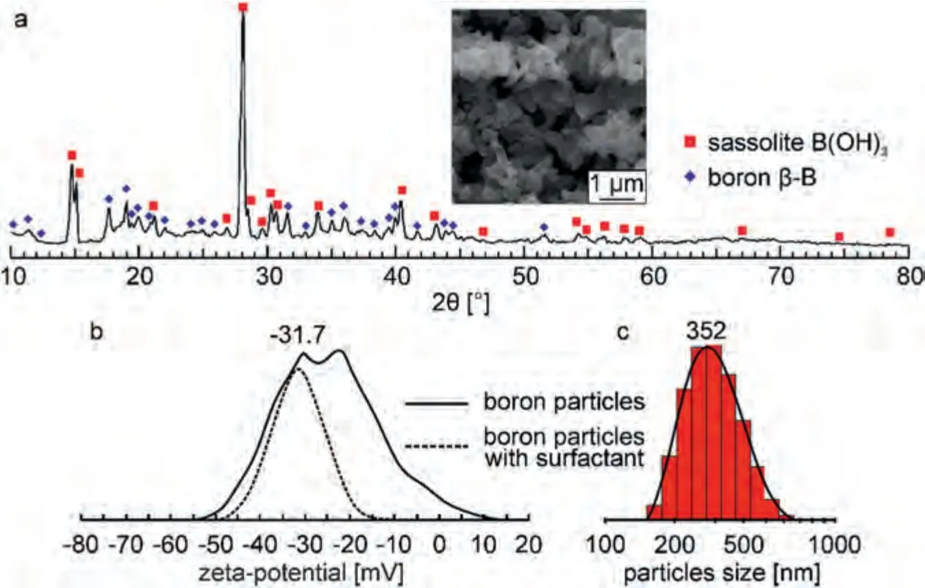
Fig.1.XRD patterns of B particles (a),distribution of the ξ-potential of particles without and with the addition of surfactant (b),particle size distribution(c).The inset shows the SEM image of boron particles.
2.3.Formation of PEO coatings
PEO coatings on an Mg alloy were formed in a two-stage bipolar polarization mode.In the anode phase,the current was 2 A throughout the entire process;in the cathode phase at the first stage,the voltage was–30 V;at the second stage,the voltage changed from–30 to–10 V.The polarization frequency is 300 Hz,the duration of the anode and cathode periods is 0.01 s.The duration of the PEO was 800 s.The plot of voltage change during PEO is shown in Fig.2.During the formation of coatings,the rms values of the applied potential difference were used.The electrolyte temperature(12 °C) was controlled using a Smart H150–3000 chiller(LabTech Group,UK).
2.4.Study of the composition, structure and morphology of coatings
The phase composition of the surface layers was studied using a D8 Advance X-ray diffractometer (XRD) (Bruker,Germany) with CuKαradiation in the 2θangle range from 10° to 80° with a step of 0.02° and an exposure time of 1 s at each point.The search program “EVA” with the data bank“PDF-2” was used for determination of phases.

Fig.2.Voltage changes during the PEO for coatings formed in a silicatefluoride electrolyte without(PEO)and with the addition of 5 g L–1 B particles(PEO-B).
To analyze the chemical composition,X-ray photoelectron spectroscopy (XPS) was used using a SPECS device (SPECS,Germany)with a 150 mm hemispherical electrostatic analyzer.The spectra were excited by AlKαradiation.The binding energy was calibrated using the C1s line (285.0 eV).An ion beam with an Ar+ion energy of 5 keV was used to etch the sample.The etching time was 5 min;the average etching rate was 10 ˚A s–1.
The surface morphology and cross sections of the coatings were studied using an EVO40 scanning electron microscope (SEM) (Carl Zeiss,Germany) equipped with an Aztec X-act device (Oxford Instruments,UK) for energy dispersive spectroscopy (EDX).Cross sections of the coatings were prepared as follows:metal plates were poured with ViaFix epoxy resin (Struers А/С,Denmark) into a mold with a diameter of 30 mm.Then they were subjected to mechanical processing with grinding paper with a decrease in the size of abrasive grains to 14–20 μm and polished on a Tegramin 25 grinding and polishing machine (Struers A/S,Denmark).The polishing steps included grinding with fine abrasives and polishing with diamond slurries.After all stages of polishing,the prepared cross section was processed in an ultrasonic bath in isopropyl alcohol.
Coating porosity was calculated from SEM image data analysis using ImageJ software (National Institutes of Health,USA).The proportion of the area occupied by pores on the entire visible surface of the coatings was estimated using Eq.(2) [56]:
where:(Sp)iis the area of theipore,S0is the area of the analyzed surface.
The method of digital processing of SEM images using software algorithms is one of the most common methods for determining the apparent porosity of the surface of PEO coatings,being a functional,accurate and efficient tool[45,58,59].
The Gwyddion 2.45 software (Czech Metrology Institute,Czech) determined the sizes of all pores in theS0section with an area of 160×220 μm2.Then,using these data in the Origin software (OriginLab Corporation,USA) a histogram of the distribution of pores by size was created.Statistical analysis performed at Origin allowed a log-normal distribution to be created from which the most common pore size(rp)was determined.
Surface roughness was studied by non-contact optical surface profiling(OSP).We used an OSP370 instrument installed on an M370 electrochemical workstation (Princeton Applied Research,USA).Data were analyzed using Gwyddion 2.45 software.The analysis of the surface topography is presented in the form of the most common roughness parameters:Ra(arithmetic mean of the absolute values of the profile heights)andRz(average of the absolute values of the heights of the five highest peaks of the profile and the depths of the five deepest valleys).
2.5.Macroscopic cross-section determination for the sample interaction with thermal neutrons
An experimental evaluation of the macroscopic cross section of the interaction of the obtained samples with thermal neutrons was carried out on a neutron activation analysis device based on a252Cf radionuclide neutron source of the NK252M11 type (JSC SSC RIAR,Russia).The total neutron flux was 109s–1.The device consists of an activation zone and a spectrometric complex.In the activation zone,the studied samples are irradiated,and theγ-spectrometric complex makes it possible to measure the induced activity.Plexiglas was used as a moderator of252Cf fission neutrons,which ensures the maximum flux of thermal neutrons in the activation zone.
The spectrometric complex is based on a GC2018 coaxial HPGe detector (Canberra Industries,USA).The energy resolution of the detector is 1.8 keV at a radiation energy of 1332 keV.The relative detection efficiency at a given radiation energy is 20%.The range of gamma radiation energies for determining the induced activity of the sample is 50–1600 keV.
The gamma spectra were measured using the eSBS v.1.6.7.0 program (Green Star Technologies,Russia).The measurement results were processed using the Gamma v.1.0 program (Green Star Technologies,Russia).
To determine the macroscopic cross section of the interaction of the synthesized material with neutrons,indicators based on europium (Eu) were used,which were placed behind the sample in the irradiation channel.The151Eu isotope(isotope abundance is 47.8%) is characterized by a high cross section for the151Eu(n,γ)152m1Eu reaction.The reaction cross section for thermal neutrons is 3300 b,and the resonance integral is 1790 b.High cross sections for interaction with neutrons make it possible to use thin europium foils,which greatly simplifies the procedure for determining the induced activity of the indicator.The half-life of the daughter reaction product 1152m1Eu is 9.31 h,which provides a high rate of analysis (the optimal activation time is 9–12 h,the time for measuring the induced activity is 2–5 h).
For the producing indicators,an aqueous solution of EuCl3was used,the concentration of europium was 25 g L–1.The solution was poured with an automatic pipette into a plastic cuvette (1.16×1.16 cm2,side wall height is 0.8 mm,wall thickness is 0.8 mm).For uniform distribution of the solution over the volume of the cuvette,filter paper was placed on the bottom of the cuvette.
To determine the macroscopic cross section of the interaction of neutrons with the test material,a series of experiments was carried out to determine the neutron flux density after the beam passed through the test samples.To do this,an indicator plate was installed in the corresponding position of the neutron collimator.The collimator is made in the form of a plastic cylinder (Ø is 28.5 mm with 35 mm high) placed(perpendicular to the axis) in a standard plastic cuvette (Ø is 65 mm with 55 mm high) filled with boron (Fig.S1).The quality of collimation was preliminarily checked and the optimal position of the indicator in the irradiation channel was selected (Tables S1,S2).
For the experiments,an indicator was used,the content of europium in which was 3.75 mg (Fig.S2).In front of the indicator,on the path of the neutron beam,samples of Mg alloy without coating (Mg),with PEO and PEO-B coatings were placed.
To determine the initial neutron flux density,the indicator plate was activated in the absence of a sample.The duration of activation was 16 h.The time of measurement of the induced activity of the indicator plate was 2 h,and the time of holding the indicator before reactivation was at least 3 days.
The induced activity of the indicator was determined from the gamma line of the daughter product of the reaction151Eu(n,γ)152m1Eu–Eγ=841 keV.The intensity of the line was 14.2% (Fig.S3).The maximum induced activity was determined by the Eq.(3):
whereIis the intensity of the analytical signal,λis the decay constant of52m1Eu,tmeasis the duration of the spectrum measurements,qis the quantum yield of the radiation of the corresponding energy group,εis the detection efficiency of the detector,tiris the duration of activation,tcoolis the exposure time of the sample after the end of activation.
Measurement of the activity of the irradiated indicator gives a value proportional to the parameterR(Eq.(4)):
whereσthis the radiative capture reaction cross section for thermal neutrons,Φthis the thermal neutron flux density,Iresis the resonance integral,Φresis the resonance neutron flux density.
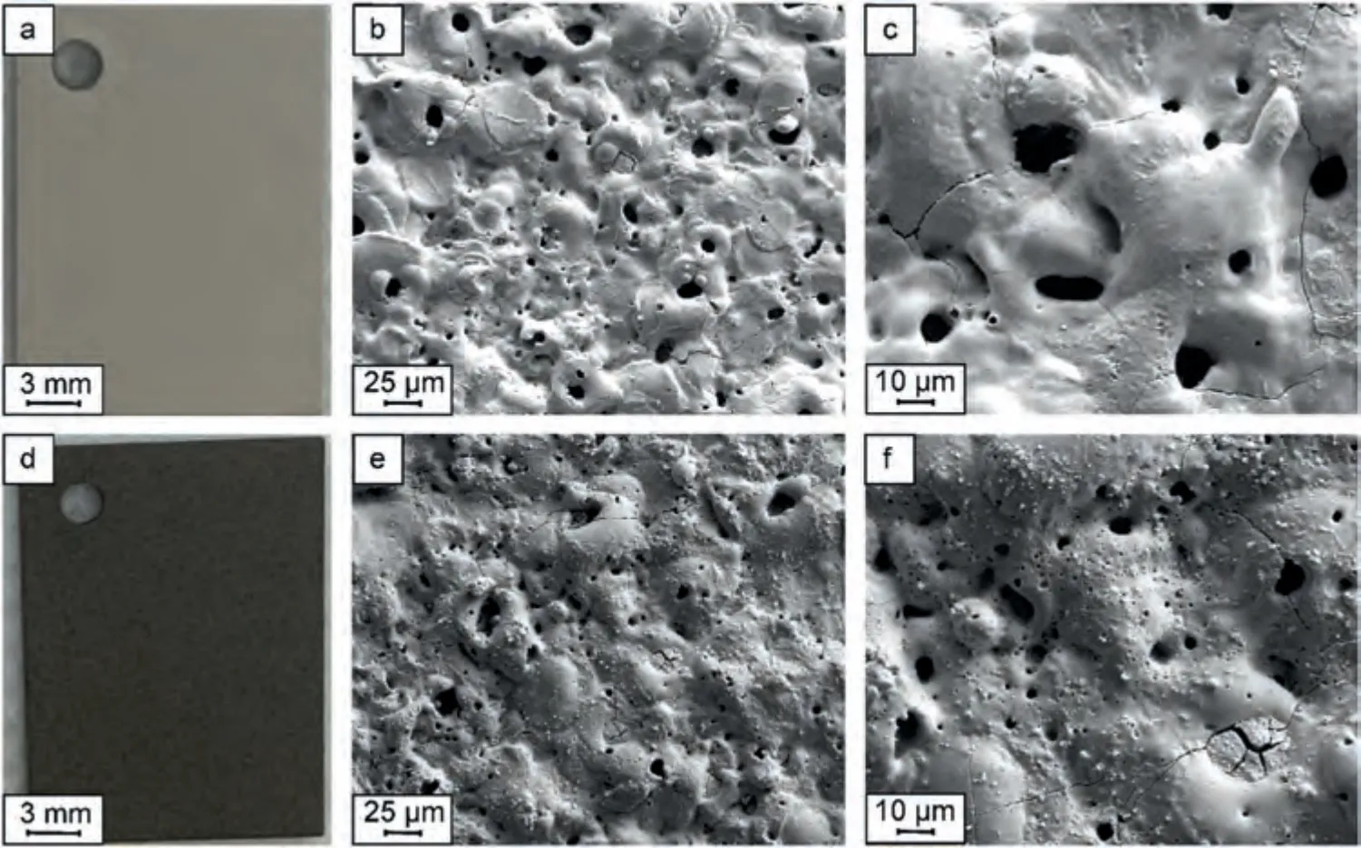
Fig.3.Optical (a,d) and SEM (b,c,e,f) images of the formed coatings at different magnifications: PEO (a–c),PEO-B (d–f).
To determine the cross section for the interaction of the studied samples with neutrons of individual energy groups,an indicator placed in a cadmium shell was irradiated.The113Cd isotope has a thermal neutron capture cross section near 20,000 b,interacting weakly with faster resonant neutrons.Based on the data on the induced activity of the indicator after its irradiation in the cadmium shell and without it,the flux density of resonant (Eq.(5)) and thermal (Eq.(6)) neutrons behind the sample was calculated:
whereAis the maximum induced activity of the indicator,Mis the molar mass of the target substance,δis the isotope abundance,NAis the Avogadro constant,mis the europium mass in the tracer,Φthis the thermal neutron flux density,andΦresis the resonance neutron flux density.
The calculation of the macroscopic cross section of the interaction of the material under study is performed in the approximation of a single act of interaction of neutrons with the sample,in accordance with Eq.(7):
whereΦiis the neutron flux density after the beam passes through the sample;Φ0is the neutron flux density in the incident beam;ρiis the linear density of the sample atoms,σis the macroscopic cross section of the interaction of the sample with neutrons.
To determine the radionuclide composition of the synthesized material after its operation as a material for physical protection against neutron radiation,a long-term activation of the sample was performed.The neutron flux density in the corresponding position of the activation zone is 108s–1cm–2.The activation time was 50 days.Two measurements of the spectrum were made: after one hour and six days of exposure of the sample after irradiation.The spectrum measurement time was 15 h.
The specific induced activity of140La was determined from the 487 keV (45.5%) and 328 keV (20.3%)γ-lines;then,the activity values obtained from the twoγ-lines were averaged.The activity of141Ce was determined from the 145 keVγline (48.4%),56Mn was determined from the 847 keVγ-line(98.85%),24Na was determined from the 1367 keVγ-line(99.98%).
2.6.Statistics
All the results were analyzed statistically and expressed as a mean ± standard deviation.For the calculated mathematical parameters,the error determined by the method of indirect measurements (considering the errors of the measured parameters).At least 5 samples were used for each experiment.
3.Results and discussion
3.1.Structure and composition of the resulting coatings
Fig.3 shows optical and SEM images of the surface of the formed PEO coatings.The obtained coatings (PEO-B) have a pronounced light brown color (Fig.3d),which indirectly indicates the inclusion of boron in the structure of the PEO layer.On SEM images (Fig.3e,f) at different magnifications,fusion of particles and their agglomerates is noticeable on the PEO-B surface,in contrast to the PEO surface (Fig.3b c).Such a morphology may indicate an inert inclusion of particles (without chemical reactions).

Table 1 Composition and conductivity of electrolytes used for the formation of PEO and PEO-B coatings.Thickness,porosity,size of the most common pores and roughness parameters of the formed coatings.
The thickness,porosity and size of the most common pores of PEO-B coatings are superior to these parameters for PEO coatings (Table 1).The increase in thickness can be directly related to the inclusion of particles in the coating structure[14].Additionally,these changes may be a consequence of a decrease in the electrolyte conductivity after the addition of 5 g L–1B particles (Table 1),and,accordingly,an increase in voltage during the process of coatings formation (Fig.2).Particles with a high negative electrokinetic potential and a large size in the process of anodic polarization of the metal create a barrier layer for the transfer of ions to the metal surface [15,60,61].This,in turn,leads to an increase in voltage at a fixed current density of the PEO process (Fig.2).Subsequently,higher (than for basic PEO) voltage values are due to the greater thickness of the formed oxide layer.
Almost no changes in surface roughness are observed: theRaandRzhave the same value within the measurement error (Table 1).The analysis of 3D surface maps shows an increase in the number of pits and a decrease in ridges for PEO-B coatings in comparison with PEO samples (Fig.S4).Such features in the surface morphology can also be a consequence of an increase in the power of plasma discharges in an electrolyte containing boron particles,as indicated by large values of the formation voltage (Fig.2).
The size of the most common pores,considering the dispersion of the log-normal distribution,differs slightly,in contrast to the porosity (Table 1,Fig.S5).The presence of particles in solution leads to a nonuniform distribution of the electric field,which characterizes a high strength near the particle surface [62].Therefore,a plasma discharge is highly likely to form on the surface of particles near the metal.This causes a significant increase in small pores (Fig.3c),which are practically not observed for the base PEO coating(Figs.3f,S5).
SEM in conjunction with EDX analysis made it possible to build maps of the distribution of elements over the surface and cross section of the coatings (Figs.4,5).An analysis of the distribution maps indicates that the main elements in the coating are Mg,O,and Si,which are uniformly distributed over the entire thickness of the coatings.Such elemental composition,due to the presence of magnesium oxide (MgO) and orthosilicate (Mg2SiO4) as the main compounds (Fig.6),is usual for PEO coatings obtained in a silicate-fluoride electrolyte on a Mg alloy [56,63].
The elements distribution maps also show the presence of boron both on the surface (Fig.4) and along the thickness of the coatings (Fig.5).At a large approximation,maps of the distribution of elements were obtained in a 12×12 μm2area containing fused particle agglomerates.The EDX analysis of this section made it possible to establish that these particles are pure B.Therefore,it can be concluded that the large number of particles penetrate the surface layer inertly,without interacting with the PEO coating.The boron content slightly increases near the Mg substrate,while fluorine,on the contrary,increases significantly towards the coating surface.The presence of fluorine is probably associated with sodium fluoride residues not washed out of the pores.
The XRD analysis results indicate that the main compounds of the coatings are magnesium oxide (periclase,JCPDS Card No: 00–045–0946) and orthosilicate (forsterite,JCPDS Card No:01–084–1402).The formation of these compounds in the course of plasma-chemical synthesis was described in detail in our previous works[63].On the diffraction pattern of the PEO-B coating (Fig.6),the presence of peaks of boron or its compounds is not observed,which is due to the low content of these phases (up to 10 at.%).The magnesium peak (JCPDS Card No: 00–035–0821) in the diffraction pattern is due to the penetration of X-rays to the metal substrate.Thus,no differences between the PEO and PEO-B coatings in the phase composition are observed.
X-ray photoelectron spectroscopy confirms the inclusion of boron particles in the PEO-B coatings.The high resolution XPS spectrum and the chemical composition of the coatings formed in the electrolyte containing 5 g L–1of B particles is presented in Table 2 and Fig.7.A low intensity peak corresponding to 1s-B is present in the inset (Fig.7).The surface of the sample consists of the elements contained in the electrolyte (Na,F,Si,O,B) for PEO or the coating substrate(Mg).The shape of the spectra and the content of elements indicate the presence of oxidized forms of MgO and SiO2in the coating,which can also be magnesium orthosilicate Mg2SiO4,according to XRD data (Fig.6).The presence of an intense 1s-C peak with a high content before etching with Ar+ions and a low content after etching is a consequence of surface contamination before the experiment.Taking this into account,note that the result after etching is the most objective elemental content.The content of B in the PEO-B coating corresponds to 1.5 at.%.Its state,according to the binding energy 1 s (193.6 eV),is characterized by the oxidation stateB+3.This implies that boron at a content of 1.5 at.% is in the oxidized form B2O3.Thus,part of the boron is in the composition of the coating in this state.The presence of this compound may be associated with the occurrence of an oxidation reaction in the channel of the most powerful plasma discharges.

Fig.4.SEM image and maps of the distribution of elements over the surface of the PEO-B coating at various magnifications.
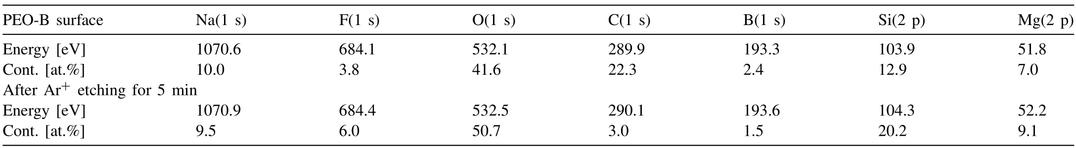
Table 2 Elemental composition of the PEO-B surface before and after Ar+ etching,determined from XPS results.
After etching the top layer of the coating with Ar+ions,the content of oxygen,magnesium and silicon increases,which is due to the high content of oxide and magnesium silicate in it (Table 2).Moreover,after etching,the content of 1s-B in the coating decreases from 2.4 to 1.5 at.%.This is due to the reduction of the oxidized form of boron after etching,or a decrease in the content of B in the greater depth.Apparently,most of the powerful plasma discharges,in which boron oxidation is possible,are formed at the last stages of the process,when the main barrier layer has already been formed.As a result,the main part of the oxidized boron is in the near-surface layer.Note that the low boron content determined by XPS reflects only the surface layer up to 10 nm thick.Therefore,it is likely that the PEO-B coating may contain boron in an amount greater than 1.5 at.%.
3.2.Absorption of neutron radiation by coatings
The results of studying the absorption of neutron radiation by the developed materials indicate the following (Table 3):a sample of Mg alloy (1.5 mm thick) retains about 4.9%of the total thermal neutron flux.This is due (Table S3) to heavy metal alloying additives (up to 0.3 wt.% of Ce,up to 2.2 wt.% of Mn) and impurities in the metal (up to 0.06 wt.%of La),as well as the absorption of neutrons by magnesium.The base PEO-coated sample shows a similar result within the measurement error.
A PEO-B sample significantly reduces the induced activity of the indicator,which is due to the absorption of neutrons in the coating’s volume (Table 3).The PEO-B sample retains 16.3% of the thermal neutron flux.In this case,as was shown above,the metal substrate retains no more than 5% of the incident thermal neutron flux,and,consequently,11.4%of the neutrons are absorbed by the coating material.Comparing the results for PEO and PEO-B,it can be argued that the increased value of the absorption capacity of the PEO-B coating is due to boron contained in the PEO coating formed on an Mg alloy.
Due to the introduction of B particles into the composition of the PEO layers,the macroscopic cross section for the interaction of the material with thermal neutrons was 30.80±4.49 b.This is 3.8 times higher than the similar value for Mg alloy without coating.

Fig.5.SEM image and maps of the distribution of elements along the thickness of the PEO-B coating.
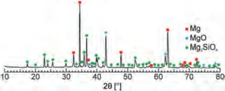
Fig.6.XRD pattern of the PEO-B coating.
The stability of the coating composition is an important parameter that determines the structure and properties of the sample.Due to numerous nuclear transformations in powerful neutron fields,a gradual change in the composition of the coating is possible.This process is accompanied with a corresponding change of the cross section for the interaction of the coating with thermal neutrons.A preliminary calculation was carried out for a thin layer of a boron-containing coating(0.065 mm).Thus,when a PEO-B sample is irradiated with a252Cf radionuclide source with a flux of 2 108neutron s–1cm–2,the decrease in the boron content in the sample will not exceed 0.00033% within 50 days.When the coating near the reactor core is irradiated with a flux of 1012neutron s–1cm–2,within 50 days the decrease in the boron content in the sample will not exceed 1.65% (Supplementary Data).
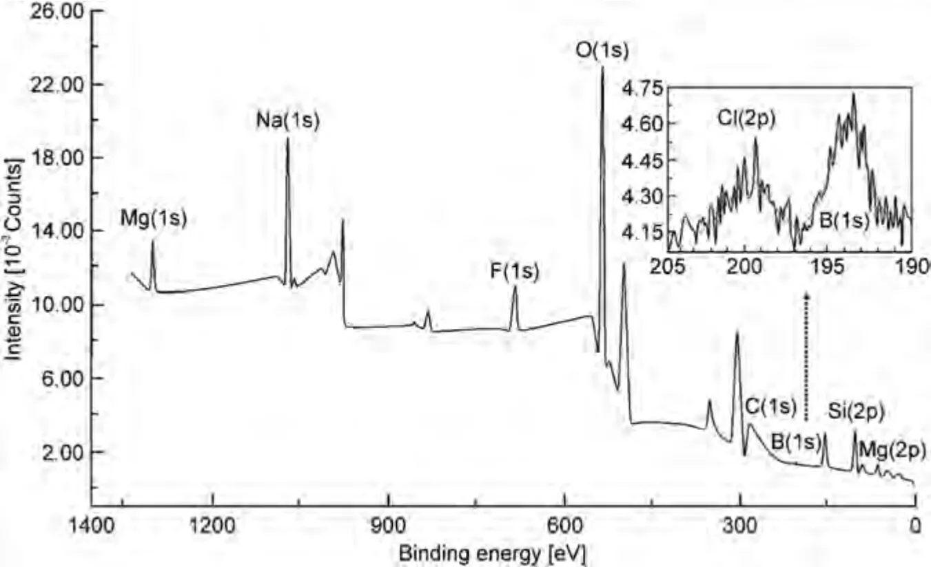
Fig.7.XPS spectrum of the PEO-B coating.
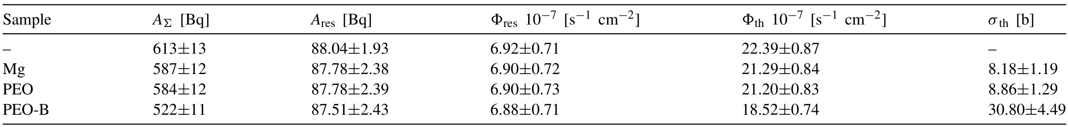
Table 3 Activity of the indicator when it is irradiated with a flux of thermal and resonant neutrons (AΣ) and when it is irradiated with a flux of resonant neutrons(Ares),flux density of resonant (Φres) and thermal (Φth) neutrons;the macroscopic cross section for the interaction of thermal neutrons with the sample material(σth).
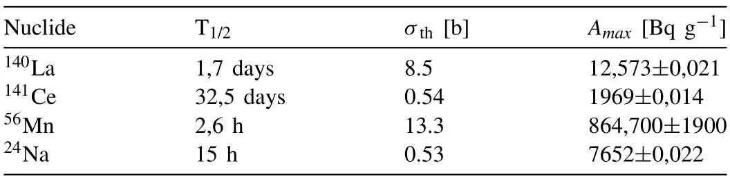
Table 4 Results of determining the induced activity of the PEO-B sample.
The results of determining the radionuclide composition of the synthesized material after its operation as a material for physical protection against neutron radiation are given in Table 4.It has been established that under the considered activation conditions,the induced activity of the PEO-B sample is due to the accumulation of short-lived radionuclides140La,141Ce,56Mn,24Na (Table 4).These radionuclides are produced as a result of the reaction of radiative capture of thermal neutrons by nuclei139La,140Ce,55Mn,23Na,respectively.
The maximum induced activity of the sample under these activation conditions was 886.9 ± 1.9 Bq g–1.The main contribution to the induced activity (97.4%) comes from the short-lived56Mn isotope.Long-lived nuclides under these activation conditions were not identified.The short half-life of most of the resulting radionuclides makes it possible to significantly reduce the induced activity of the material by short-term holding of samples after irradiation.Thus,holding the sample for 6 days made it possible to reduce the induced activity of the sample by more than 300 times to 2.799±0.018 Bq g–1.At the same time,the gamma spectrum of the sample became almost identical to the spectrum before activation (Fig.8).
After a six-day exposure of the sample,its induced activity is represented only by the residual activity of140La and141Ce(Fig.8).An additional decrease in the induced activity is possible by reducing the content of impurities in the sample,for example,La.
4.Conclusions
PEO coatings were formed on a Mg–Mn–Ce alloy in an electrolyte containing 5 g L–1of crystalline boron particles.B particles are mostly incorporated into the structure of PEO coatings inertly,without chemical reactions or in the form of B2O3.Formed coatings are thicker and more porous than base PEO coatings.This is due to the change in the formation voltage during PEO.
A method has been developed for determining the macroscopic cross section for the interaction of a synthesized material with thermal neutrons.
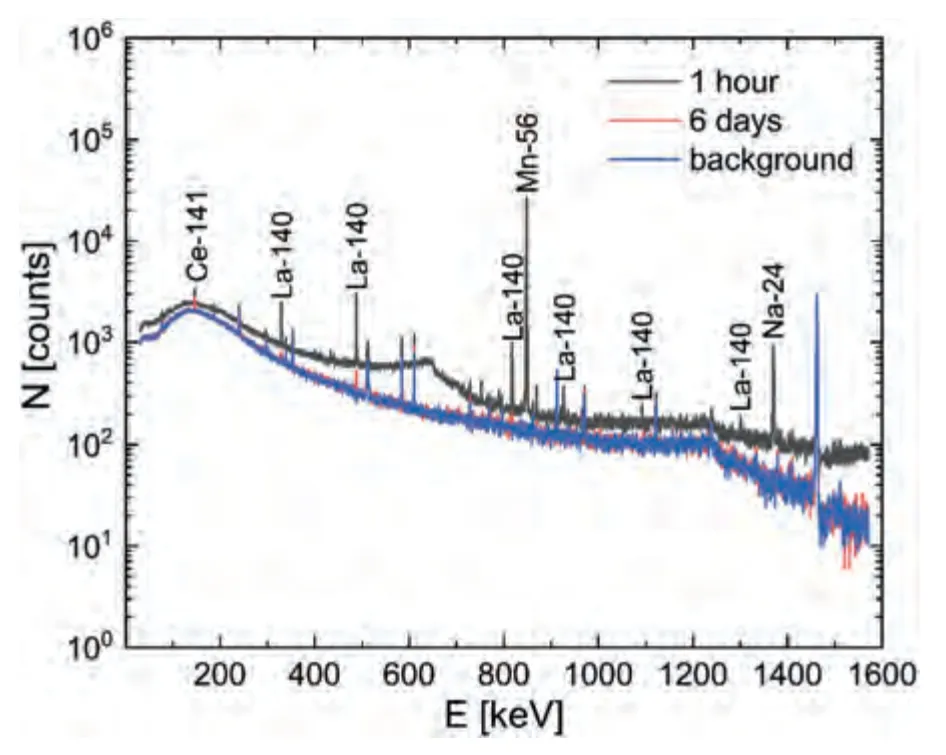
Fig.8.Gamma spectra of background radiation and PEO-B sample after 1 h and 6 days of exposure after 50 days of activation.
A thin (64 μm) boron-containing PEO coating makes it possible to increase the macroscopic thermal neutron capture cross section by a factor of 3.8,compared to uncoated metal.
Developed coatings have great potential for application in the field of nuclear technology,as well as in the aerospace industry.
Declaration of competing interest
None.
Funding
The formation of coatings,as well as XRD,XPS,and OSP analyzes was supported by Russian Science Foundation Grant No.22-73-10149,https://rscf.ru/project/22-73-10149/.The SEM,EDX analyzes and study of absorption of neutron radiation by coatings was supported by the Russian Science Foundation Grant No.23-13-00329,https://rscf.ru/project/23-13-00329/.
Supplementary materials
Supplementary material associated with this article can be found,in the online version,at doi:10.1016/j.jma.2023.09.018.
杂志排行

Journal of Magnesium and Alloys的其它文章
- Improvements in mechanical,corrosion,and biocompatibility properties of Mg–Zr–Sr–Dy alloys via extrusion for biodegradable implant applications
- Ultrasonic solidification mechanism and optimized application performances of ternary Mg71.5Zn26.1Y2.4 alloy
- Superplastic behavior of a fine-grained Mg-Gd-Y-Ag alloy processed by equal channel angular pressing
- GO/MgO/Mg interface mediated strengthening and electromagnetic interference shielding in AZ31 composite
- Experimental and theoretical studies on two-dimensional vanadium carbide hybrid nanomaterials derived from V4AlC3 as excellent catalyst for MgH2
- Achieving high-strain-rate and low-temperature superplasticity in an ECAP-processed Mg-Y-Er-Zn alloy via Ag addition