Loading direction dependence of asymmetric response of pyramidal slip in rolled AZ31 magnesium alloy
2023-12-27YuzhiZhuDewenHouKixunChenZidongWng
Yuzhi Zhu ,Dewen Hou ,Kixun Chen ,Zidong Wng,∗∗
aSchool of Materials Science and Engineering, University of Science and Technology Beijing, Beijing 100083, China
b Micron School of Materials Science and Engineering, Boise State University, Boise, ID 83725, United States
c Center for Nanoscale Materials, Argonne National Laboratory, Lemont, IL 60439, United States
Abstract Textured magnesium alloys usually exhibit anisotropic mechanical behavior due to the asymmetric activation of different twinning and slipping modes.This work focuses on the
Keywords: Magnesium;
1.Introduction
With the increasing demand for lightweight,wrought magnesium alloys become promising candidates as structural materials in the automotive and aircraft industries [1,2].Magnesium alloys have typical hexagonal close-packed (HCP) crystal structure and usually exhibit severe mechanical anisotropic behaviors during deformation,which limits their suitability in many applications [3–6].The generation of strong texture of the wrought magnesium alloy during the post-manufacturing process leads to complex mechanical responses under different loading conditions [7].For example,the yield strength of rolled AZ31 magnesium alloy gradually increases when the tensile loading direction moves from the rolling direction to the transverse direction [8].The preferred grain orientation also affects fatigue properties.Wang et al.[9] reported that rolled AZ31 magnesium alloy shows the highest and lowest fatigue strength when the cyclic loading is applied along the rolling direction and the 45° away from the rolling direction.
The mechanical anisotropy is related to the complex activation of deformation modes in basal-textured magnesium.When a tensile loading is applied along the c-axis of the unit cell,{102} tensile twinning and slipping are the dominant deformation modes [10–12];when the tensile strain is perpendicular to the c-axis,dislocation slips dominate and{102}tensile twins cannot be activated [13–15].Mainly,there are two types of slips in magnesium alloys,〈a〉 type glides on the (0001) basal and the {100} prismatic planes,and 〈c+a〉type glides on the {101} first-order and the {112} secondorder pyramidal planes.Among all the dislocation slips,only〈c+a〉 type pyramidal slip can accommodate c-axis deformation [16,17].The Burger’s vector of 〈c+a〉 type slip is 1/3〈113〉,which is much larger than that of 〈a〉 type slip (1/3〈110〉).The critical resolved shear stress (CRSS) of pyramidal slip is relatively high,which is∼80 times larger than that of basal slip in pure Mg at ambient temperature[18,19].When a single-crystal magnesium sample is subjected to a compressive loading along [0001] direction at room temperature,the dominant deformation mechanism is 〈c+a〉pyramidal slip,and the sample always shows high yield stress and work hardening rate [20–23].Additionally,previous studies confirmed that polycrystalline magnesium alloys containing more 〈c+a〉 slips show higher ductility compared to single-crystal magnesium alloys [24–27].
Asymmetric activation behaviors of pyramidal slip are commonly observed in HCP metals under different loading directions.For example,Jones and Hutchinson [35] studied the deformation behaviors of Ti-6Al-4V alloys under different loading conditions and found cross-slip behaviors of pyramidal dislocations under c-axis compression,but restrictions of pyramidal slip moving on the {101} plane under c-axis tension.On the contrary,Long et al.[36] found under c-axis compression pyramidal slips in Zr-2.5Nb are restricted in the{101} pyramidal plane,which is thought of as the primary slip plane,while cross-slip of pyramidal slip occurs under caxis tension.Furthermore,Tang and El-Awady [29] reported an anisotropy in the CRSS of {101} first-order pyramidal slip,that near-screw and near-edge dislocations contain the lowest and the highest CRSS.
The correlation between 〈c+a〉 pyramidal slip behaviors and loading directions is expected in HCP magnesium alloys.However,it is not thoroughly clear how the 〈c+a〉 pyramidal slips behave under different loading directions.In this work,the asymmetric responses of pyramidal dislocations,depending on loading directions,are studied in textured AZ31 magnesium alloy using the electron backscattered diffraction(EBSD) and transmission electron microscopy (TEM) techniques.A detailed study of the slip morphologies is performed using diffraction analysis.Double cross-slip of 〈c+a〉 dislocations tends to take place under c-axis compression and climb-like dissociation of 〈c+a〉 dislocations occurs under c-axis tension in AZ31 magnesium alloys.
2.Materials and experimental methods
Commercial rolled Mg-3Zn-1Al (AZ31) magnesium alloy sheet was used in this work.In the following descriptions,for convenience,normal direction,rolling direction,and transverse direction are denoted as ND,RD,and TD,respectively.The as-received sample was heat treated at 200 °C for 5 h to relieve the residual stress.For tensile tests,dog-bone samples with dimensions of 4 mm in width (RD),10 mm in gage length (ND),and 10 mm in thickness (TD) were cut from the alloy sheet.For compression tests,samples with the dimension of 10 (ND) × 10 (RD) × 8 mm (TD) were prepared.Uniaxial mechanical tests,including both tensile and compressive tests,were conducted along the ND with a constant strain rate of 10-3s-1using a CMT 5150 machine at ambient temperature.
Samples for EBSD characterizations were mechanically ground by sandpaper,then electrochemical polished with commercial AC2 solution.The microstructure observation was focused on the center of the ND-RD plane.EBSD observations were carried out by the JOEL-JEM 7800F field emission scanning electron microscope.The voltage was 20 kV and the step size was 1 μm.Obtained data was processed using HKL Channel 5.0 software.For TEM characterizations,thin foils with a thickness of∼0.5 mm were cut from the center of the ND-RD plane in the deformed samples and mechanically grounded to∼80 μm.Discs with 3 mm diameter were then punched from thin foils,followed by ion-milling.TEM observations were performed in an FEI Tecnai TF30 scanning transmission electron microscope at the acceleration voltage of 300 kV.
The initial microstructure of the rolled AZ31 magnesium alloy is exhibited in Fig.1.Grain boundaries with angles less than 15° are defined as low angle grain boundaries (LAGBs,identified as white lines in the inverse pole figure (IPF) map),and grain boundaries with angles above 15° are defined as high angle grain boundaries(HAGBs,identified as black lines in the IPF map).The grain size of the initial-state sample ranges from∼5–50 μm.As mentioned above,dislocations can be removed during the stress relief heat treatment process,while the microstructure maintains.Therefore,no pre-existing dislocations would affect the results.The initial microstructure shows a very strong basal texture,that the c-axis of most grains is nearly aligned parallel to the ND.

Fig.1.The IPF map of the initial-state textured AZ31 magnesium alloy.
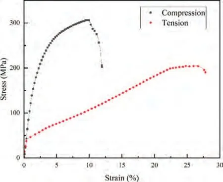
Fig.2.Stress-strain curves of AZ31 magnesium alloy under compression(black line) and tension (red line) along the ND.
3.Results and discussion
3.1.Mechanical responses of the compressive and tensile samples
Fig.2 displays the mechanical behaviors of AZ31 magnesium alloy deformed under compression (black line) and tension (red line) along the ND.In the compressed sample,the peak stress is∼305 MPa and the elongation is∼7.73%.No obvious yield plateau is observed in the black line at the early deformation stage,indicating that dislocation slips accommodate the deformation strain.In the tensile test,the specimen failed at∼24%strain with the ultimate tensile stress∼204 MPa.A yield plateau can be seen in the tensile curve,which suggests that twinning activation occurs [37–41].The ductility for the ND-tension sample is much higher than that for the ND-compression sample.The tensile twin is believed to be responsible for the higher ductility in the ND-tension sample [42–44].The twinning activation can cause the crystal reorientation and stimulate the activation of the dislocation slips within the twins,which in turn,leads to a higher ductility in the ND-tension sample.
3.2.Microstructure analysis in the compressive and tensile samples
Fig.3 shows the microstructures of the deformed AZ31 magnesium alloy.Fig.3a shows the IPF of the sample which is compressed along the ND to a strain of∼4.3%.The c-axis of most matrix grains is nearly aligned along the ND,which exhibits a typical(0001)basal texture.When the applied compressive stress is parallel to the c-axis of the unit cell,tensile twin is prohibited and only dislocations are activated.The corresponding grain boundaries component is shown in Fig.3b,where the {102} tensile twin boundaries are highlighted by red lines.A small number of {102} twin lamellas are activated and no {101} contraction twin is observed under NDcompression.In addition,massive LAGBs are observed in the IPF map,indicating that dislocation slip dominates under this deformation condition.Fig.3d shows the IPF map of the sample deformed under tension along the ND to a strain of∼4.9%.Compared to the ND-compression sample,{102}tensile twins are prevalent in the ND-tension sample (Fig.3b and e).It is noted that the change in crystal orientation from matrix to twin plays an important role in the strain accommodation.In a single-crystal magnesium,when a tensile strain is applied parallel to the c-axis,tensile twins start nucleation and growth,converting the twined regions into softer orientation for basal slip [45].In this work,the difference of the cases with tension/compression loadings along the ND,the mechanical and texture components are consistent with the Schmid factor (SF) response.
The SF values for basal (black rectangle) and pyramidal slip(red dot)systems of all matrix grains in these two samples were calculated and collected in Fig.3c and f.Under compression along the ND,the SF values for basal and pyramidal slip system in the matrix region are mainly ranging from 0 to 0.5 and 0.3–0.5,respectively (Fig.3c).Under tensile loading along the ND,the SF values for basal and pyramidal slip system are mainly ranging from 0 to 0.5 and 0.2–0.5 (Fig.3f).The high SF values for pyramidal slip under both conditions mean when the applied stress reaches its CRSS,the pyramidal slip can be activated.
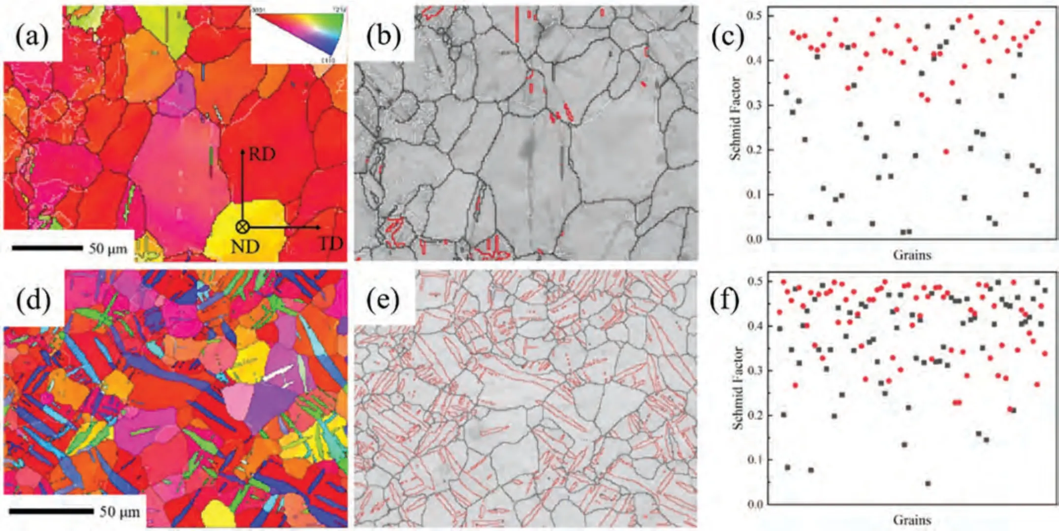
Fig.3.Microstructure of the deformed AZ31 magnesium alloy:(a)-(c)are IPF map,grain boundary map and Schmid factor analysis for the specimen deformed to∼4.3% under compressive loading along the ND;(d)-(f) are IPF map,grain boundary map and Schmid factor analysis for the specimen deformed to∼4.9%under tensile loading along the ND.
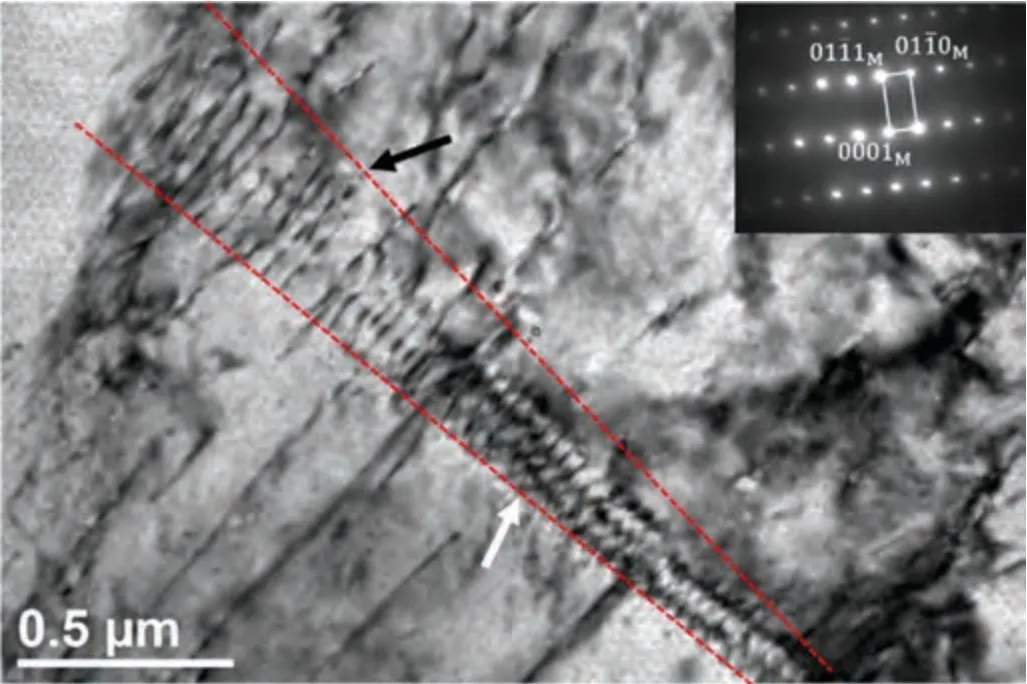
Fig.4.BF TEM image of the compressed AZ31 sample to a strain of∼4.8%along the ND.The SAEDpattern is inserted at the right top,indicating the zone axis is [110].
3.3.Slip behaviors during compression along the ND
To further investigate the anisotropic slip behaviors in the deformed samples,TEM analysis was performed to study the dislocation types and their morphologies.Fig.4 shows the morphology of the deformed AZ31 sample compressed to a strain of∼4.8% along the ND.The corresponding selected area electron diffraction (SAED) pattern is inserted at the top right of the TEM image.The image is taken with the beam direction nearly along the [110] zone axis.In the bright-field(BF)TEM image,activated dislocations exhibit different morphologies:individual straight or stepped dislocation lines with a length of∼1–2 μm,and a long dislocation wall (marked by red dash lines),with a length of∼2 μm.The dislocation wall consists of dislocations with different morphologies.The right part is assembled by a series of dense stepped dislocation lines (marked by the white arrow),while the left part is loosely arranged by straight dislocation lines (marked by the black arrow).Moreover,some individual straight dislocation lines are absorbed by the dislocation wall.As proposed by Beer and Barnett [46],dislocation walls can continuously absorb dislocations to mature to HAGBs,depending on the dislocation mobility.Here,considering the deformation condition,when a textured AZ31 magnesium alloy is compressed along the ND,which is an unfavorable loading condition for{102} tensile twinning activation,the most active deformation modes should be dislocation slips.It can be assumed that as the strain further increases,the dislocation wall can absorb more single dislocations and transfer to HAGBs,which can be responsible for the grain refinement.
To further identify the type of the dislocation wall within the matrix,BF TEM images were taken under two-beam diffraction conditions using different diffraction vectors (g=011 andg=0002) around the [110] zone axis.Fig.5 shows the dislocation structures in the deformed AZ31 sample after∼4.8% compression strain along the ND.The diffraction vector information is inserted at the top right of each TEM image.The (0002) basal plane trace is denoted by a red line (Fig.5a and b).According tog·b=0 invisible criterion,wheregis the diffraction vector andbis the Burger’s vector of the dislocation,wheng=011 is applied,both 〈a〉and 〈c+a〉 type dislocations can be observed,while wheng=0002 is applied,only dislocations containing 〈c〉 components are in contrast and 〈a〉 type dislocations are out of contrast.In Fig.5a,several straight and curved dislocation lines are observed underg=011 (marked by orange arrows),indicating 〈a〉 or 〈c+a〉 type dislocations are activated.In addition,many dislocation walls are apparent (marked by white arrows),which may consist of either 〈a〉 or 〈c+a〉 dislocations based ong·b=0 criterion.
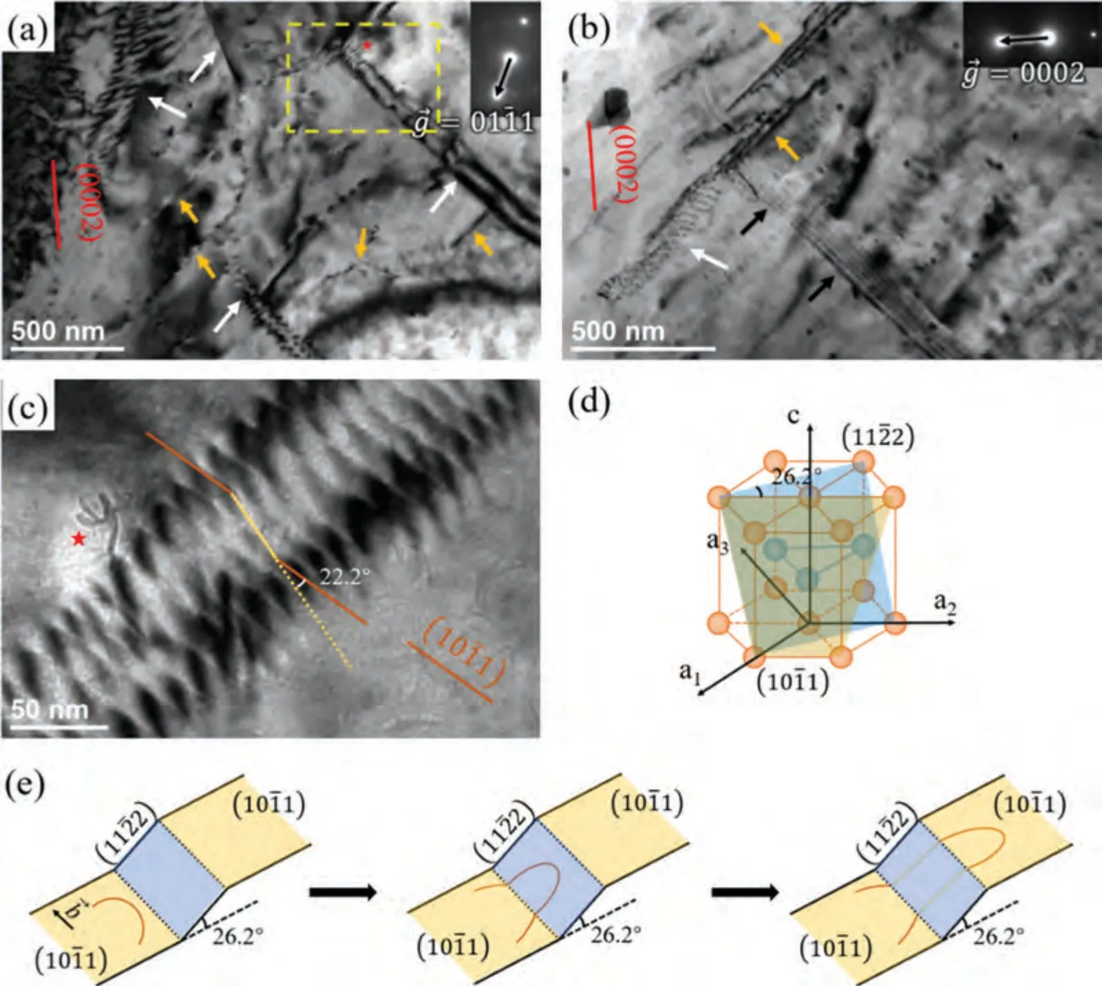
Fig.5.BF TEM images under the two-beam diffraction conditions near [110] zone axis: (a) under g=011,(b) under g=0002.(c) BF TEM image of an enlarged area in Fig.5a shows the zigzag 〈c + a〉 dislocation wall.(d) Orientation relationships of (101) and (112) plane in HCP unit cell.(e) Illustration of double cross slip.The traces of (0002) and (101) planes are indicated by red and dark orange lines.The dislocation walls,singe dislocation lines,and stacking faults are indicated by white,orange,and black arrows,respectively (For interpretation of the references to color in this figure legend,the reader is referred to the web version of this article.).
A higher-magnification BF TEM image (Fig.5c) underg=011 diffraction condition reveals the detailed structure of the dislocation wall in Fig.5a.The(101) type Ⅰpyramidal plane trace is denoted by a dark orange line (Fig.5c).The dislocation wall is composed of a series of ordered zigzag dislocation lines.Similar single zigzag dislocation lines were observed in Mg and HCP high-entropy phase before [47,48].The straight segments of the stepped lines at both ends,which are highlighted as dark orange lines,lie parallel to the {101}plane trace,indicating that they move on the{101}pyramidal plane.The angle between the connected yellow line and the dark orange line is∼22.2°,which is close to the angle value between {101} first-order and {112} second-order pyramidal planes (26.2°) (see the illustrations in Fig.5d).Therefore,the zigzag dislocation line consists of two segments of {101}pyramidal dislocations and one segment of {112} pyramidal dislocation.{101}plane and{112}plane share the zone axis[113] (Fig.5d).When 〈c+a〉 dislocations move from the{101} plane to the {112} plane by cross slip,then move to the {101} plane again,they leave a stepped dislocation line behind.Furthermore,these dislocations tend to accumulate uniformly to minimize energy,and a dislocation wall forms finally.Thus,we can conclude the formation of dislocation walls in ND-compression magnesium is attributed to the double cross-slip of 〈c+a〉 dislocations.Comparably,in Fig.5b,underg=0002 condition,a dislocation wall is still observed,together with a series of narrow fringes (marked by black arrows) emanating from this dislocation wall.These narrow fringes with different contrasts are identified as stacking faults[33].The observed dislocation wall underg=0002 condition should consist of dislocations containing 〈c〉 components.
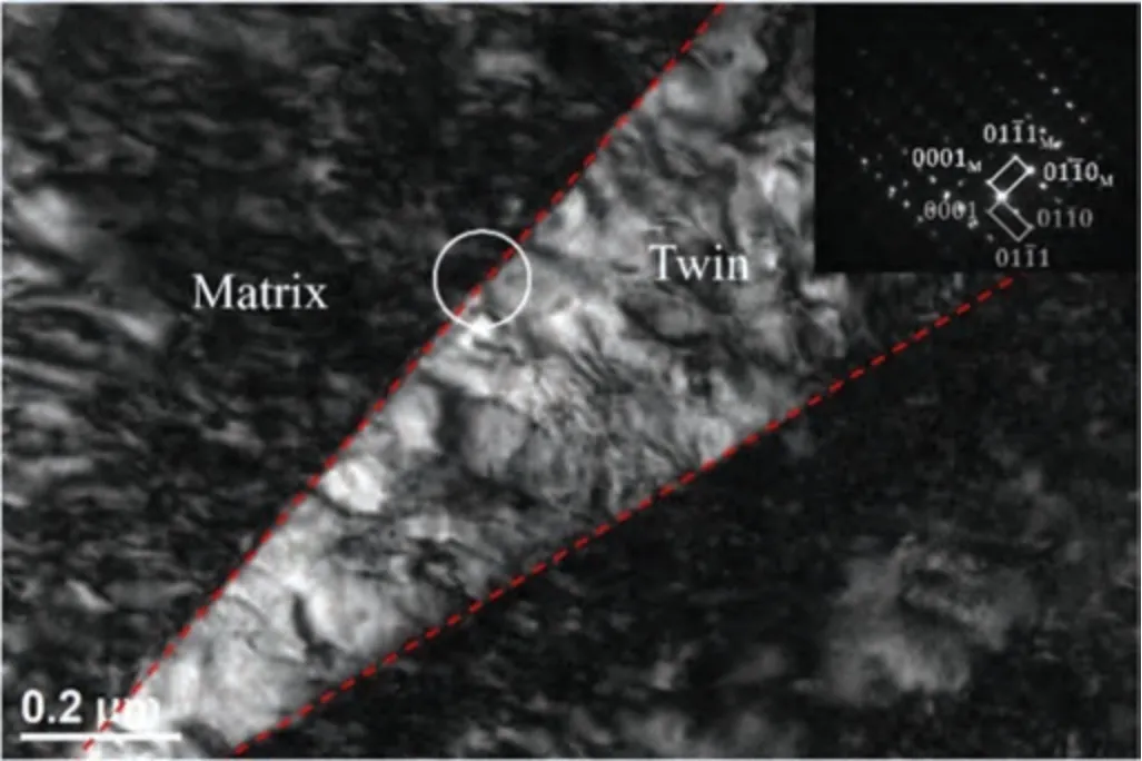
Fig.6.BF TEM image of the deformed AZ31 sample to a tensile strain of∼4.3% along the ND.The SAED pattern is inserted at the right top,indicating the zone axis is [110].
Fig.5e shows the schematic diagrams of the double crossslip process and the formation of zigzag dislocation lines.The blue plane is the {112} second-order pyramidal plane and the yellow plane is the {101} first-order pyramidal plane.These two planes share the [113] zone axis (dashed black line).In the beginning,the 〈c+a〉 dislocation (identified by the orange curved line) lies on the {101} plane,with the Burger’s vector along the [113] direction.As the dislocation starts to move,the {101}〈113〉 dislocation cross slips to the {112} plane and continues to move forward to the{101} plane again,leaving pure edge 〈c+a〉 segments on the {112} plane (identified by yellow straight lines).Similar phenomenon of the cross-slip was predicted under c-axis compression,while was not observed under c-axis tension in Tang and El-Awady’s simulation work [32].They assumed that it is the prevalent twinning activation that prohibits the cross-slip under c-axis tension.The simulation results from Wu and Curtin [49] suggested that the cross-slip depends on the energy barrier between pyramidal Ⅰ/Ⅱplanes.As illustrated in a previous study [50],the increased ductility of rare earth element-containing Mg alloys is attributed to the propagations of easy-glide pyramidal slips stimulated by the cross-slip.Jones and Hutchinson reported a 40% higher yield strength in a deformed Ti-6Al-4V alloy,where 〈c+a〉 dislocations tend to cross-slip rather than moving on {011} plane[35].
3.4.Slip behaviors when tension along the ND
Fig.6 shows the tensile twin morphology of the AZ31 magnesium sheet deformed to∼4.3% tensile strain along the ND.The twin boundaries are highlighted by red dash lines.The SAED pattern,at the upper right corner of the figure,was carried out at the interface between the matrix and the twin(highlighted by the white circle) along the [110] zone axis.The {102} tensile twin has a lenticular shape,contributed to the serrated morphologies of coherent twin boundary (CTB)and basal-prismatic (BP/PB) interface [51–53].Furthermore,dislocation lines are apparent both in the twinned region and the matrix region.To further understand the dislocation behaviors in the matrix,detailed dislocation structures with higher magnification are shown below.
Fig.7 shows the dark-field (DF) TEM images of the dislocation structures within the matrix in rolled AZ31 magnesium alloy deformed to∼4.3% tensile strain under different twobeam conditions near the [110] zone axis.The diffraction vectors are illustrated at the top right corner of each figure.The plane traces inserted in Fig.7 indicate the orientations of lattice planes that possible active dislocation slips align.Many dislocation lines,with a length of∼550 nm,are activated (Fig.7a).According tog·b=0 criteria,these dislocation lines observed underg=0002 should be 〈c+a〉 type dislocations.Furthermore,many of them are aligned nearly parallel to the {112} plane trace (marked by green arrows),suggesting that they should be{112}second-order pyramidal dislocations.In addition,a stepped dislocation forms (highlighted by green and yellow dash lines).The segments parallel to the green and yellow dash lines lie on {112} second-order and {101} first-order pyramidal planes,indicating that limited cross-slip occurs under current loading condition.Fig.7b shows the DF TEM image of dislocation lines underg=011 near the [110] zone axis.Both stepped and curved dislocation lines,as well as dislocation loops are observed.Three types of stepped dislocation lines are highlighted by yellow,green,and red dash lines.The first type contains segments lying parallel to the {101} first-order pyramidal plane and the(0001) basal plane.The second type contains segments that align parallel to the {112} second-order pyramidal plane and the (0001) basal plane.And the last one contains dislocation lines that are parallel to the {101} first-order and the{112} second-order pyramidal plane,as well as the (0001)basal plane.It is noted that no dislocation segment is parallel to the {100} prismatic plane trace,indicating that prismatic slip is unfavorable to generate in the matrix under current deformation.All these dislocation lines contain segments lying on the (0001) basal plane,suggesting that either {101}first-order or {112} second-order pyramidal dislocation tends to dissociate on the (0001) basal plane.These straight segments lying on basal planes were also observed in Mg micropillar [54] and single-crystal Mg [55].As reported in the reference [54],these segments are confirmed as glissile by bothin-situTEM and atomic simulation.A climb-like transition of partial 〈a〉 occurs on the basal plane to form a new〈c+a〉 dislocation,which agrees with the simulation results in the reference [56].In consequence,a zigzag dislocation line forms.To be noticed,a zigzag dislocation line,with three different oriented segments,can be observed in Fig.7b,indicating that dissociation and cross-slip may happen simultaneously.
In summary,the deformation behaviors in the NDcompression and the ND-tension samples are different.In the ND-compression sample,cross-slips frequently occur,and tend to pile up and rearrange in parallel.In the ND-tension sample,the dominant deformation modes are tensile twinning,associated with planar slips distributed both within the matrix and the twin region.

Fig.7.DF TEM images of dislocations in deformed AZ31 magnesium alloy under the two-beam diffraction conditions near [110] zone axis: (a) under g=0002,(b) under g=011.The diffraction vector is at the right top of each figure.The plane traces identified by diffraction analysis are inserted for the determination of the lattice plane that each dislocation lies (For interpretation of the references to color in this figure,the reader is referred to the web version of this article.)..
4.Conclusions
In this study,commercial AZ31 magnesium sheets were deformed in tension and compression along the normal direction.Twinning and slipping behaviors were studied by EBSD and TEM analysis.Conclusionsare drawn as follows:
(1) Tensile twins are prevalent in the sample stretched along the ND,while dislocation slips dominate in the sample compressed along the ND.
(2) Dislocation walls,composed of zigzag pyramidal dislocation lines,are observed in the sample compressed along the ND.The double cross-slips of dislocations between{101}and{112}pyramidal planes contribute to the zigzag morphologies.
(3) Individual zigzag dislocation lines are observed in the matrix region in the sample stretched along the ND.Dissociation of pyramidal slips on basal planes results for the zigzag morphologies.
The current study is mainly focused on the〈c+a〉dislocation behaviors usingex-situmicroscope technology.Detailed study on the evolution of pyramidal slips is still needed,especially in micro-and nano-scale by means of real-time characterizations.Additionally,the interaction between dislocation slips and other interfaces,such as twin boundary,precipitation interface,stacking fault,etc.,is believed as a key mechanism in plastic deformation.These deformation mechanisms require further investigations,and the authors are working on these issues.
Declaration of competing interest
The authors declare no competing interest.
Acknowledgments
This work was supported by the Bejing Municipal Natural Science Foundation (No.2214072),the Interdisciplinary Research Project for Young Teachers of USTB (Fundamental Research Funds for the Central Universities) (FRF-IDRY-20–034) and by the Office of China Postdoctoral Council under Award No.YJ20200248.Use of the Center for Nanoscale Materials,an Office of Science user facility,was supported by the U.S.Department of Energy,Office of Science,Office of Basic Energy Sciences,under Contract No.DE-AC02–06CH11357.
杂志排行

Journal of Magnesium and Alloys的其它文章
- Improvements in mechanical,corrosion,and biocompatibility properties of Mg–Zr–Sr–Dy alloys via extrusion for biodegradable implant applications
- Ultrasonic solidification mechanism and optimized application performances of ternary Mg71.5Zn26.1Y2.4 alloy
- Superplastic behavior of a fine-grained Mg-Gd-Y-Ag alloy processed by equal channel angular pressing
- GO/MgO/Mg interface mediated strengthening and electromagnetic interference shielding in AZ31 composite
- Experimental and theoretical studies on two-dimensional vanadium carbide hybrid nanomaterials derived from V4AlC3 as excellent catalyst for MgH2
- Electrochemical synthesis of boron-containing coatings on Mg alloy for thermal neutron shielding