Dynamic response of UHMWPE plates under combined shock and fragment loading
2023-10-09ChunZhengZhaoLuShengQiangRuiZhangQianChengZhangJunYangZhongZhenYuZhaoTianJianLu
Chun-Zheng Zhao ,Lu-Sheng Qiang ,Rui Zhang ,Qian-Cheng Zhang ,Jun-Yang Zhong ,Zhen-Yu Zhao ,Tian Jian Lu ,**
a State Key Laboratory of Mechanics and Control of Mechanical Structures,Nanjing University of Aeronautics and Astronautics,Nanjing,210016,PR China
b MIIT Key Laboratory of Multi-functional Lightweight Materials and Structures (MLMS),Nanjing University of Aeronautics and Astronautics,Nanjing,210016,PR China
c State Key Laboratory of New Textile Materials and Advanced Processing Technologies,Wuhan Textile University,Wuhan,430200,PR China
d School of Aerospace,Xi'an Jiaotong University,Xi'an,710049,PR China
Keywords:UHMWPE composite Ballistic performance Combined blast and fragment loading Impact test Finite element simulation
ABSTRACT Ultra-high molecular weight polyethylene (UHMWPE) fiber composite has been extensively used to construct lightweight protective structures against ballistic impacts,yet little is known about its performance when subjected to combined blast and fragment impacts.Built upon a recently developed laboratory-scale experimental technique to generate simulated combined loading through the impact of a fragment-foam composite projectile launched from a light gas gun,the dynamic responses of fullyclamped UHMWPE plates subjected to combined loading were characterized experimentally,with corresponding deformation and failure modes compared with those measured with simulated blast loading alone.Subsequently,to explore the underlying physical mechanisms,three-dimensional (3D) numerical simulations with the method of finite elements (FE) were systematically carried out.Numerical predictions compared favorably well with experimental measurements,thus validating the feasibility of the established FE model.Relative to the case of blast loading alone,combined blast and fragment loading led to larger maximum deflections of clamped UHMWPE plates.The position of the FSP in the foam sabot affected significantly the performance of a UHMWPE target,either enhancing or decreasing its ballistic resistance.When the blast loading and fragment impact arrived simultaneously at the target,its ballistic resistance was superior to that achieved when subjected to fragment impact alone,and benefited from the accelerated movement of the target due to simultaneous blast loading.
1.Introduction
High performance protective structures are increasingly constructed using ultra-high molecular weight polyethylene(UHMWPE) fiber composite,attributed mainly to its low density,high specific (tensile) strength,and particularly,excellent penetration resistance [1].In today’s battlefield environment,such lightweight protective structures will often not only withstand projectile penetration but also face major threats from shallowburied mines,improvised explosive devices (IEDs),and shelled warheads,the latter generating intensive loadings that combine blast and fragment impacts [ [2-4]].It is therefore of vital importance to explore how UHMWPE protective constructions perform under such combined blast and ballistic loading.
The ballistic performance of UHMWPE composite has been extensively investigated using experimental,theoretical,and numerical approaches,resulting in a wide variety of protective applications.Based on a non-dimensional analysis of experimental data,it was argued that the high specific stiffness/strength of UHMWPE led to its superior resistance against projectile penetration[5],which was further validated by theoretical modeling built upon the mechanism of membrane stretching [6].Subsequent research revealed that the dynamic deformation and failure mechanisms of a UHMWPE plate subjected to ballistic impact were dependent upon its thickness.While the theory of membrane stretching held for relatively thin UHMWPE plates,the deformation and failure of thicker plates contained two sequential stages[7]:in the first stage,shear plugging dominated local deformation and failure;in the second stage,large scale bulging deflection via progressive degradation played a dominant role.In addition,the ballistic performance of a UHMWPE target was influenced by both its microscale fiber architecture and macroscopic morphology.For instance,relative to a UHMWPE laminate constructed with either unidirectional or helical piles,a cross-ply laminate exhibited superior ballistic limit [8,9].In a previous study,the present authors experimentally demonstrated that a multilayered cross-ply UHMWPE laminate subjected to projectile penetration absorbed more impact energy and hence possessed a better ballistic limit,in comparison with its monolithic counterpart having equal mass[10].Based upon full three-dimensional (3D) finite element (FE)simulations,the authors argued that the multi-layered UHMWPE laminate led to smaller tensile stresses on its rear face and a more significant pull-in effect at its edges,causing larger back-face deflection and hence enhanced ballistic limit [10].The nose shape of the projectile has been identified as another important factor influencing the ballistic performance of UHMWPE laminates.For instance,relative to projectiles having spherical or flat noses,the resistance of a UHMWPE target to a conical-nosed projectile was inferior,for the impact energy of the former was mainly absorbed via global deformation such as bulging and membrane stretching[11];in contrast,a conical-nosed projectile perforated the target mainly by pushing aside the fibers rather than breaking them.Such characteristics caused more localized deformation and failure of the target underwent the strike of a conical-nosed projectile,leading to less efficient energy absorption [12].It should however be pointed out that existing studies focused predominantly on the deformation/failure of a UHMWPE target in the impact area,with little attention paid to the dynamic behavior of the target near its edges [13].Recent experimental results [14] revealed that a fullyclamped UHMWPE plate subjected to the impact of a 42 mm diameter projectile experienced severe shear-out failure at the clamped edges,thus affecting significantly its ballistic performance.
In addition to studying ballistic performance,increasing focus has been placed on exploring how UHMWPE protective structures would dynamically behave under impulsive loadings (e.g.,TNT explosions and mine blasts).Based upon experimental and numerical results,typical deformation/failure modes that have hitherto been identified included out-of-plane bulging,pull-in at the edges,in-plane shearing,delamination,and high temperature melting caused by the explosion [15].Compared with a CFRP(carbon fiber-reinforced plastic)beam having equal areal density,a UHMWPE beam was not only approximately 1.5 times thicker but also had a lower interlaminar shear strength.Accordingly,when subjected to identical shock loading,the UHMWPE beam would experience less bulging at its center and could sustain a higher failure impulse.Nonetheless,for both beam types,the main failure mode was tensile fiber breakage at the clamped edges [16].In recent years,inspired by its exceptional specific strength,UHMWPE composite has been used to construct lightweight explosion-proof walls with UHMWPE laminates,and numerical results suggested that the failure criterion of maximum principal strain could characterize quite adequately its damage induced by blast loading[17].Further,again under blast loading,the dynamic responses of sandwich panels with multi-layered aluminum foam/UHMWPE laminate cores were investigated,and it was concluded that the incorporation of UHMWPE laminate in the sandwich core reduced the deflection of the front face of the sandwich,but increased the deflection of its back face [18].
Experimentally,combined blast and fragment loading was found,generally speaking,to induce more severe damage on a target than that generated by equivalent blast loading acting alone[19].Using FE simulations,the former researchers [3] also demonstrated that the deflection of the target under combined blast and fragment loading exceeded the sum of those generated when the blast and fragment loadings were separately applied.The synergetic effect of such combined loading on target deformation/failure was further found to be dependent upon the interval of arrival time on target between the two types of loadings [20].For instance,if the target was already deforming as a result of the prior arrival of blast loading before the fragment,such deforming could change the subsequent response of the fragment-target system in three aspects: providing initial kinetic energy to the target,changing plastic deformation in the dished region of the target,and altering the shear force during perforation.It was,therefore,important to account for the synergetic effect of combined blast and fragment loading when designing protective structures.At present,existing research on combined blast and fragment loading focused mainly on protective structures constructed with metals[20],concretes [21,22],sandwiches [23,24],and glass fiberreinforced plastics [25].Therefore,how would a UHMWPE target perform when subjected to such combined loading remained elusive.
Experimentally speaking,although combined blast and fragment loading has been achieved using various shelled charges[23],such approaches typically suffered from high costs and great risks,thus were unsuitable for laboratory testing.To address the issue,as shown schematically in Fig.1(a),the present authors[20]proposed a novel laboratory-scale technique by embedding a metallic FSP(fragment simulating projectile,lengthland diameterd1) into a cylindrical aluminum (Al) foam sabot (lengthLand diameterD),and then launched the FSP-foam composite projectile via a lightgas gun: through the sudden release of compressed gas,the projectile was accelerated to strike a target.Traditionally,when a solid projectile (fragment) was loaded into the light-gas gun barrel,ballistic impact tests could be performed [26,27];upon replacing the solid projectile with an Al foam projectile,the technique could be used to perform simulated shock tests[[16,28-30]].In contrast,embedding a FSP into an Al foam sabot to construct a composite projectile enabled performing combined shock and projectile impact tests.As shown in Fig.1(a),the Al foam projectile contained a cylindrical hole of diameterd2,which was slightly larger thand1.A FSP resided within the hole,with the distance between its top face and the surface of the foam sabot denoted as Δd.Since the penetration mechanism of a flat-nosed projectile and the corresponding numerical simulation model had been extensively investigated,the flat-nosed projectile was selected to construct the composite projectile in the present study.When the composite projectile struck a target,the FSP started to penetrate the target while the foam applied a shock loading to the target,the latter was capable of mimicking typical blast loading due to the unique compressive properties of Al foams [20],as illustrated in Fig.1(b).With the proposed impact technique,whether the FSP or the foam sabot struck the target firstly was controlled by varying Δd: when Δd>0(e.g.,Fig.1(a)),the foam sabot struck the target first,followed by the impact of the FSP;when Δd=0,the foam and the FSP struck the target simultaneously;when Δd<0,the FSP struck first,followed by the foam.
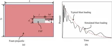
Fig.1.(a)FSP-foam composite projectile for simulated combined blast and fragment loading via a light-gas gun,and(b)variation of pressure transmitted to target by an aluminum foam projectile and comparison with that caused by typical blast loading (e.g.,TNT explosion).
In the present study,the FSP-foam composite projectile of Fig.1(a) was employed to investigate the dynamic responses of UHMWPE targets subjected to combined blast and fragment loading,both experimentally and numerically.The paper was organized as follows.Section 2 was devoted to experimental set-up for combined blast and fragment loading via light-gas gun,including material characterization,experimental measurements,and analysis of experimental results.In Section 3,full threedimensional FE simulations were performed and validated against experimental measurements.In Section 4,the validated FE model was employed to explore underlying physical mechanisms and quantify how the performance was affected by varying Δd.The comparison was also made with the case when the UHMWPE targets were subjected to simulated blast loading alone,with particular focus placed upon variations in deformation/failure modes due to load type change.
2.Experiments
2.1.Material characterization
Two types of projectiles were prepared to impact UHMWPE target plates via a light-gas gun,the closed-cell Al foam projectile(FP) was used to perform simulated blast loading alone;the FSPfoam composite projectile (CP),as shown schematically in Fig.1(a),was employed to generate combined blast and fragment loading.For both projectile types,the Al foam(acquired from Anhui Yiming New Material Technology Co,Ltd,PR China)had a density of 378 kg/m3,a length ofL=85 mm and a diameter ofD=57 mm.The FSP was made of AISI 4340 steel,with a length ofl=20 mm and a diameter ofd1=7.62 mm.A cylindrical hole of diameterd2=8 mm was drilled in the CP to house the FSP.
The FP specimen was compressed via a MTS machine at a nominal strain rate of 6.7×10⁻³s-1.The measured nominal stress σ versus nominal strain ε curve was shown in Fig.2,which could be divided into three stages.In the first stage,the foam exhibited a linear response till the initiation collapse strain εCwas reached;the subsequent stage was often referred to as the plateau stage,wherein the stress remained near constant till the densification strain εDwas reached;the final stage was the densification stage,with the stress rising rapidly till full densification was reached.During the entire compression process,the energy absorption efficiency of the foam was defined as
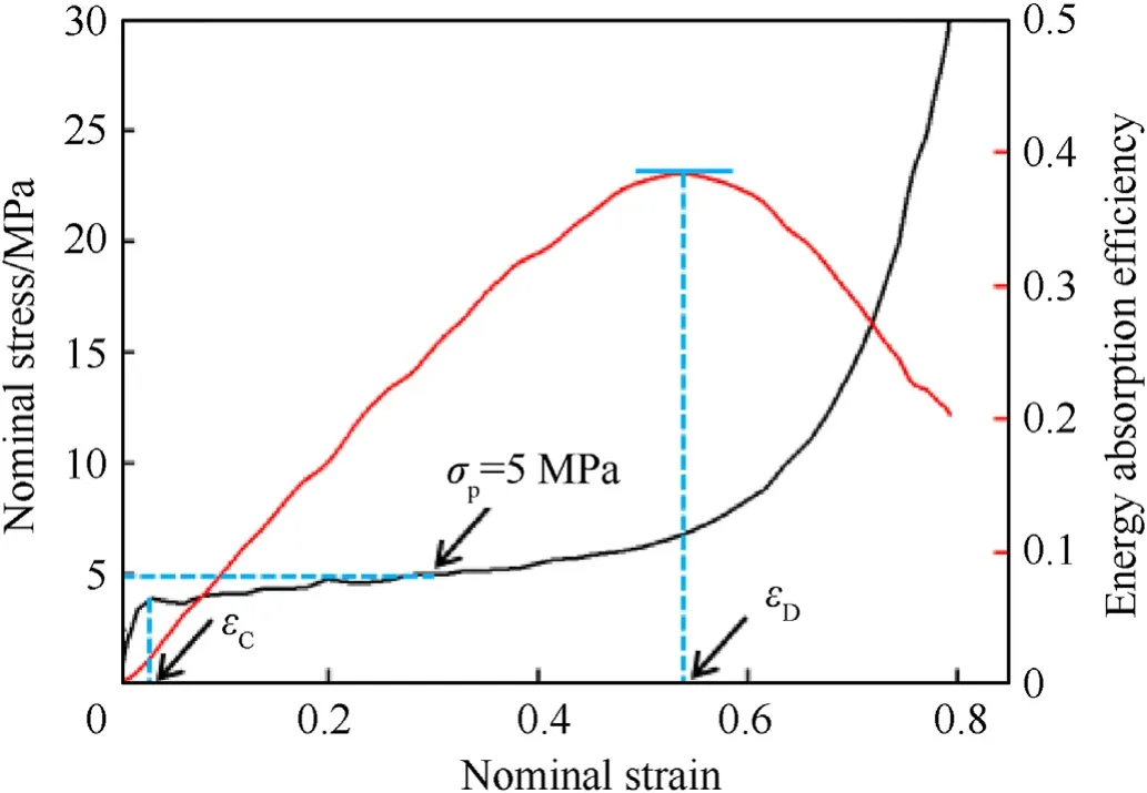
Fig.2.Quasi-static compressive stress versus strain curve of Al foam at a nominal strain rate of 6.7 × 10⁻³ s-1.
2.2.When η reached its peak,namely
The corresponding nominal strain was the densification strain εD[31].Consequently,upon defining the plateau stress σpof Al foam during uniaxial compression as Ref.[32]
It was found that σp=5 MPa,corresponding to εD=0.54,as shown in Fig.2.
The UHMWPE composite material was provided by the Beijing Tongyizhong New Material Technology Co,PR China,with a commercial grade of HA-792 and a density of 970 kg/m3.The HA-792 pre-pregs,0.15 mm thick each,consisted of two orthogonal unidirectional plies to form a [0°/90°] fiber architecture.To construct a 3 mm thick laminated plate for impact testing,24 HA-792 pre-preg layers were laid up and hot-pressed at 130 ℃ under a pressure of 13.8 MPa.As seen in Fig.3(a),the length and width of each asprepared UHMWPE target plate were 260 mm,with 16 holes of diameter Φ=11 mm drilled along its edges for mounting with M10 bolts.According to the results obtained via quasi-static tensile/compressive tests by the present authors [10],the peak tensile strength and out-of-plane compressive strength of a HA-792 UHMWPE laminate could reach 726 MPa and 1.74 GPa,respectively.
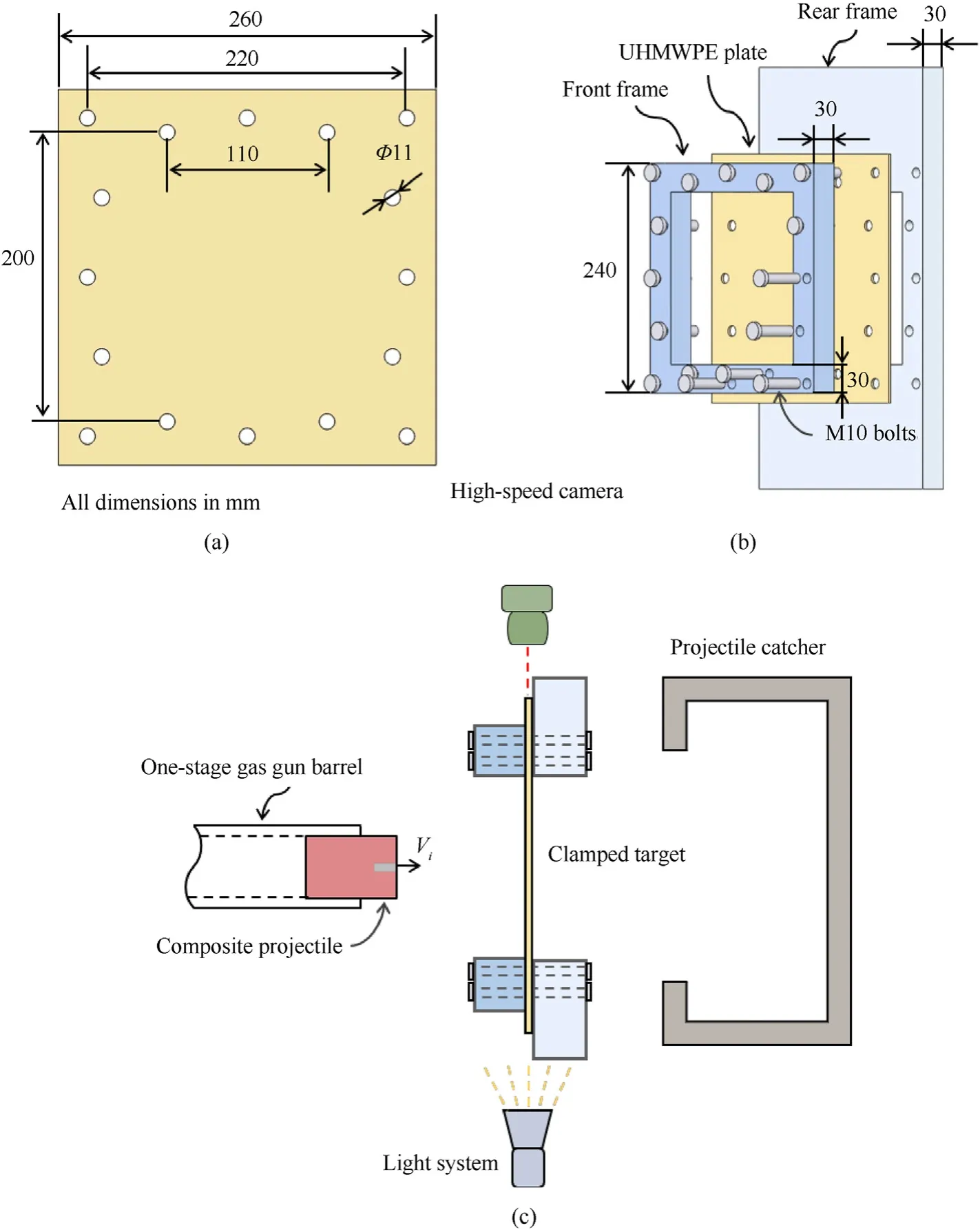
Fig.3.(a) Geometrical dimensions of a UHMWPE target plate;(b) Schematic of a clamped target plate,and (c) schematic of impact test set-up.
2.3.Experimental protocol
As shown in Fig.3(b),a UHMWPE target plate was fixed between the front and rear frames,with an exposed area of 180 × 180 mm2.Previous impact experiments revealed severe damage/failure at the clamped boundary of a UHMWPE laminate due to significant pull-in effect [16].Hence,the front frame was purposely designed to be smaller than the UHMWPE test sample,so as to avoid additional damage in the bolted region,as shown in Fig.3(b).
For impact testing,a one-stage light-gas gun was employed to launch projectiles toward clamped UHMWPE targets.A high-speed camera(I-SPEED 513)was used to capture the deformation process,and measure the impact velocity of each projectile and the maximum deflection of each target plate,with the frame rate fixed at 15,000 and the shutter speed at 19 μs.During the test,a light system was adopted for enhanced image quality.Behind the target plate,a projectile catcher was installed such that the deformed configuration of the FSP after perforating the target could be examined.To make sure that the FSP could perforate the UHMWPE laminate,the impact velocity of the composite projectiles was set in a wide range from 160 to 414 m/s.The purpose of using the foam projectile was to compare the maximum deflection of the target under the impact of two different kinds of projectiles.When the laminate was impacted by a foam projectile with sufficiently high velocity(e.g.,>250 m/s),its boundary would completely fail,thus making it difficult to measure the maximum deflection [16].Consequently,in the present study,the impact velocity of foam projectile was limited to around 200 m/s.
In experiments,the distance between the top face of FSP and the top surface of foam sabot was kept at Δd=0 mm,i.e.,the FSP and the Al foam sabot struck the UHMWPE plate simultaneously,and the effect of the striking sequence would be only discussed numerically.
2.4.Experiment results
Table 1 summarized the experimental results for both FP(foam projectile)and CP(composite projectile)test samples,including the impact velocityViof the projectile,the residual velocityVrof the FSP,and the maximum deflectiondpof each target plate.For comparison,the maximum deflections of UHMWPE plates impacted by FP and CP with different velocities were plotted in Fig.4.Compared with the FP,the CP could generate a higher maximum deflection of the target,irrespective of the impact velocity.For instance,the maximum deflection caused by CP at 160 m/s was even 6.4% greater than that induced by FP at 214 m/s.Note however that,for the CP-7,CP-8 and CP-9 specimens,the maximum deflections were not available due to severe failure near the clamped edges under high velocity impact,as shown by images captured by high-speed camera;Fig.5(b) and Fig.5(c).
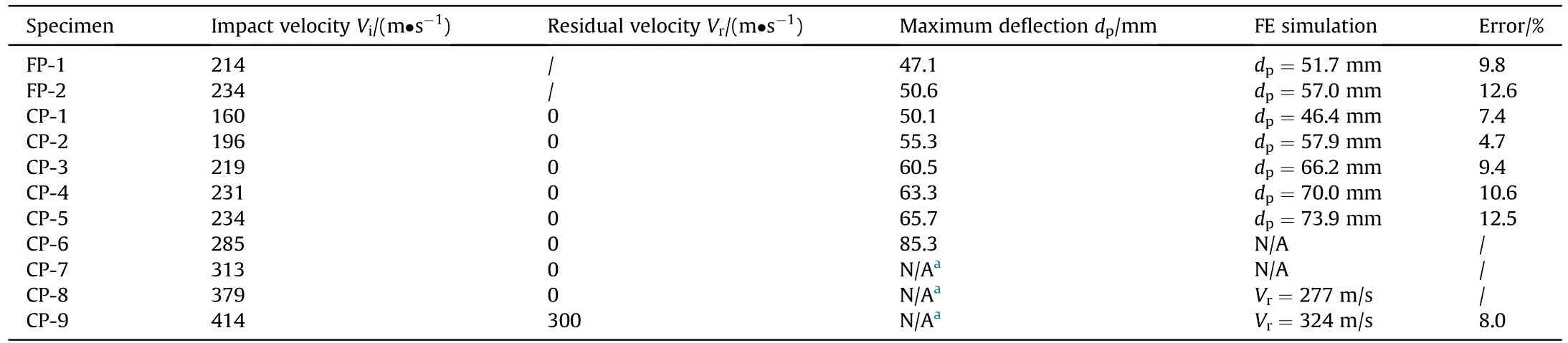
Table 1 Experimental and numerical results of UHMWPE plates impacted by foam projectiles(FP) and FSP-foam composite projectiles (CP).
Fig.4.Maximum deflection versus impact velocity for target plates impacted by foam projectile (FP) and composite projectile (CP).

Fig.5.Sequence of high-speed images of clamped UHMWPE target plates impacted by CP at (a) 234 m/s,(b) 379 m/s and (c) 414 m/s.
Fig.5 displayed the high-speed images of clamped UHMWPE plates impacted by CP with selected impact velocities,with time=0 μs indicating the initial contact between projectile and target.At 234 m/s (Fig.5(a)),the out-of-plane bulge of UHMWPE plate formed rapidly and continued to increase thereafter.At around 599 μs,the bulge reached a maximum and started to rebound(as observed at around 1265 μs).Due to the relatively low impact velocity,the FSP was unable to perforate the target.When impact velocity was increased to 379 m/s,a larger bulge formed in the target,as seen in Fig.5(b).In this case,as the bulge led to material pull-in,the material endured severe failure near the clamped edges and,at around 849 μs,was dragged out from the clamp.At around 1949 μs,the target plate failed completely at the clamped edges such that part of the material moved ahead along with the CP projectile;during the whole impact process,no FSP perforation was observed.When the impact velocity was further increased to 414 m/s,the FSP perforated the UHMWPE plate and retained a residual velocity of 300 m/s at 266 μs,as shown in Fig.5(c).The boundary failure was similar to that observed in Fig.5(b),and fiber fracture induced by FSP perforation occurred at around 1399 μs after the impact.
Corresponding to the test results summarized in Table 1,Fig.6 also presented photos of two UHMWPE specimens (FP-2 and CP-5) after being impacted at the same velocity of 234 m/s.For both cases,the UHMWPE specimens exhibited similar deformation and failure patterns:blast-induced bending deformation,pull-in at the edge,and significant failure around the bolt holes.As shown in Fig.6(a),the failure around the bolt holes of FP-2 specimen was dominated by bearing failure,featured by material extension and permanent deformation around the bolt holes.In comparison,a few bolt holes of CP-5 specimen exhibited more intensive shear-out failure,which was characterized by shear failure extension of the material to the boundary of the specimen,accompanied by the completely failed constraint of the clamping frame;Fig.6(b).The results confirmed that,relative to the FP having the same impact velocity,the CP could generate more severe failure in a clamped target plate.
When the impact velocity of CP was increased to 313 m/s,compared with the case of lower velocity impact (specimen CP-5;Fig.6(b)),more bolt holes in the specimen (CP-7) exhibited shear-out failure rather than bearing failure,and material pull-in also occurred at the edges,as shown in Fig.7(a).Although no perforation occurred,a crater induced by FSP penetration appeared at the center of the target.Fig.7(b) displayed the remnant of specimen CP-9 after being impacted at even higher velocity(414 m/s).In this case,the target was perforated by the FSP,shear-out failure occurred around almost all bolt holes,and fractured UHMWPE fibers around the perforation hole were observed.In addition to the out-of-plane views of CP-9 shown in Fig.7(b) and Fig.7(c) also displayed its cross-sectional view,from which significant delamination failure around the perforation hole was detected.

Fig.7.Deformation and failure patterns of UHMWPE target plate after being impacted by(a)FP at 313 m/s and(b)CP at 414 m/s.(c)Cross-sectional view of CP-9 specimen after FSP perforation.
The deformed configurations of composite projectiles after impacting targets at selected velocities(160,234 and 414 m/s)were presented in Fig.8.As the impact velocity was increased,the Al foam sabot was increasingly compressed due to interaction with the targets during the impact,maintaining a cylindrical configuration with almost no visible change in diameter for high-porosity Al foams typically exhibit a plastic Poisson ratio equaling to 0.In contrast,upon impacting and perforating the target,the FSP underwent little deformation,as the impact velocities considered in the present study were relatively low.
Fig.8.Deformed configurations of composite projectiles after impacting the targets at selected velocities,and the morphology of the FSP after impacting and perforating the target at 414 m/s.
3.Numerical simulations
3.1.Numerical model
Numerical simulations based upon the method of finite elements (FE) were performed with the commercially available LSDYNA.Due to the symmetry of the problem,only a quarter of the three-dimensional (3D) model was considered for a FSP-foam composite projectile impacting a clamped UHMWPE target plate,as shown in Fig.9.Note that,as the interaction between the FSP and the Al foam sabot tended to cause severe element distortions of the foam due to its low strength,the material of foam sabot above the FSP was ignored,but its mass was added to the remaining part of the foam sabot for consistency.
Fig.9.(a)Three-dimensional(3D)finite element model for a FSP-foam composite projectile impacting a clamped UHMWPE target plate(only a quarter shown due to symmetry),and (b) mesh refinement around the bolt hole.
Based upon the Lagrangian algorithm,all parts of the FE model were meshed using hexahedral SOLID 164 elements.The meshing strategy adopted in the current study was consistent with previous studies about dynamic loading and ballistic impact[20,31]:for the foam sabot,as shown in Fig.9(a),Fig.8 and Fig.12 and Fig.17 elements were adopted along its radial,circumferential and axial directions,respectively,whereas the number of elements along its outer and inner circles was the same;for the FSP,a global element size of 0.5 mm was employed.For the UHMWPE laminated plate,a mesh convergence test (global element sizedmvaried from 1 to 0.5 mm) was carried out with the impact of CP at a velocity of 196 m/s,as displayed in Fig.10(a).As the mesh size was varied,the predicted deflection of the back sheet versus the time curve was displayed in Fig.10(a).The maximum deflection tended to converge as the mesh size was reduced: to ensure the accuracy of the numerical model,dm=0.5 mm was adopted for the UHMWPE composite.To simulate local failure modes (e.g.,bearing failure and shear-out failure) captured from experiments,mesh refinement was adopted for the region around each bolt hole;Fig.9(b).A uniform element size of 1 mm was adopted for the clamping frame and bolts: the influence of mesh size was ignored for both were regarded as rigid structures.
Fig.10.(a) Sensitivity of numerically calculated deflection history of the target to element size,and (b) energy evolution history (dm=0.5 mm and Vi=196 m/s).
The UHMWPE target plate was characterized using the sublaminate model to achieve balanced efficiency and accuracy for simulating the ballistic performance of UHMWPE laminates[10].In the sub-laminate model,the UHMWPE laminate was simplified as a combination of multiple transversely isotropic sub-laminates,and each sub-laminate was homogenized by several cross-piles in the composite laminate.Cohesive contact was employed to mimic inter-laminate interaction and delamination failure,which considered the normal stress σnand shear stress σs,the normal strengthIn,and the shear strengthIs.The normal strength of cohesive contact was measured from the dynamic throughthickness tensile test,and the shear strength was approximated by the quasi-static shear result considering the dynamic effect[10].The failure criterion of cohesive contact was [33]
The Eroding-Surface-To-Surface contact option was set between the FSP and the UHMWPE target,as well as between the frame fixture,the bolts,and the target.The Automatic-Surface-To-Surface contact option was adopted for other contact interfaces,including that between the target and foam sabot as well as that between the FSP and foam sabot.
The numerically predicted energy evolution history was presented in Fig.10(b),withdm=0.5 mm andVi=196 m/s.The sum of kinetic energy,internal energy,hourglass energy and sliding energy was equal to the total energy at any time after the impact;further,during the whole impact process,neither the sliding energy nor the hourglass energy exceeded 10% of the total energy.Therefore,it was demonstrated that the current FE model reached a good balance of energy.
3.2.Material property
Due to little deformation observed during the impact tests,the FSP together with the frame fixture and bolts were regarded as rigid parts via*MAT_RIGID in LS-DYNA.As with existing studies[10,33],the UHMWPE plate was modelled using a continuum composite constitutive model (i.e.,*MAT_COMPOSITE_FAILURE_SOLID_MODE),which employed a linear elastic relationship between stress and strain
whereE,Gand ν were the Young's modulus,shear modulus and Poisson ratio,respectively.The subscriptsa,b,crepresented material axis directions of the UHMWPE composite laminate,as shown in Fig.9(a):aandbdesignated the 0°and 90°directions(i.e.,the orientation of unidirectional UHMWPE fibers),whereascrepresented the thickness direction.The keyword *MAT_ADD_ERSON was used to simulate the evolution of failure in UHMWPE laminates by deleting those elements that had failed during FE simulation:an element was deemed to fail once the value of maximum principal strain reached 0.4 or the value of compressive volumetric strain reached 0.8 or both values were reached [10].For the present UHMWPE laminate (HA-792),Table 2 listed relevant material properties (elastic module,Poisson ratios and strengths),which were validated in a previous study [10].In particular,their properties were adopted here to simulate local failure patterns observed experimentally around bolt holes,including bearing failure and shear-out failure.For a bolted cross-ply UHMWPE laminate under tensile loading,the failure of material around bolt holes was affected by the deformation and interaction between 0°and 90°piles.In the present study,due to the lack of a suitable multi-scale simulation method and reliable failure data,we could only simulate material failure around bolt holes by setting the in-plane compressive strength of the UHMWPE plate.To this end,in the present study,the in-plane compressive strength was set as 800 MPa (Table 2).Once the in-plane compressive strength exceeded 800 MPa,failure around bolt holes tended to be dominated by the tension failure,inconsistent with experimental observation.In contrast,if the in-plane compressive strength was too small,failure around bolt holes would become much more severe than that observed experimentally,leading to a significantly larger maximum deflection relative to that measured.
The closed-cell Al foam was modelled using the homogeneous constitutive model *MAT_CRUSHABLE_FOAM,with the Young's modulus and Poisson ratio set as 1.0 GPa and 0,respectively [20].The relationship between stress and volumetric strain for the Al foam was calibrated with the experimentally measured quasi-static compressive stress versus strain curve of Fig.2.For closed-cell Al foams,the compressive responses were approximately similar over a wide range of strain rates,from quasi-static to about 5000 s-1[34].Thus,the strain rate effect of Al foams was not considered in this study.
3.3.Model validation
For each UHMWPE target plate tested,the numerically predicted maximum deflections and the residual velocities of the FSP were compared with those measured in Table 1.The maximum deflections and residual velocities from numerical simulations agreed favorably well with the experimental measurements,except for the residual velocity in the case of CP-8 specimen where the predicted value was 277 m/s while the target plate was not perforated in the experiment (i.e.,Vr=0 m/s).This was attributed to the fact that the impact velocity of CP-8 specimen was close to its ballistic limit.When the incident velocity of a projectile approached the ballistic limit,it was known that the impact result of target and the residual velocity of the projectile was prone to errors,either in FE simulations or experimental measurements.
In terms of deformation and failure patterns,the present FE simulation results agreed well with experimental measurements,as shown in Fig.11.In particular,details of deformation/failure patterns were successfully simulated,including the bulge deformation of UHMWPE target and the pull-in at its edges,as well as bearing/shear-out failures around the bolt holes.However,remarkable deviations in the location and number of (bearing/shear-out) failures were present in CP-6 specimen;Fig.11(c).As shown in Fig.11(c),while shear-out failure occurred experimentally only around the intermediate bolt holes at each clamped edge of the UHMWPE plate,more significant shear-out failure than bearing failure occurred around all the bolt holes in FE simulation.Such severe boundary failure forced the target to be dragged out from the clamp,enabling it to continuously move forward during FE simulation.As a result,the maximum deflection of CP-6 in the simulation was not applicable and hence its maximum deflection was not listed in Table 1.
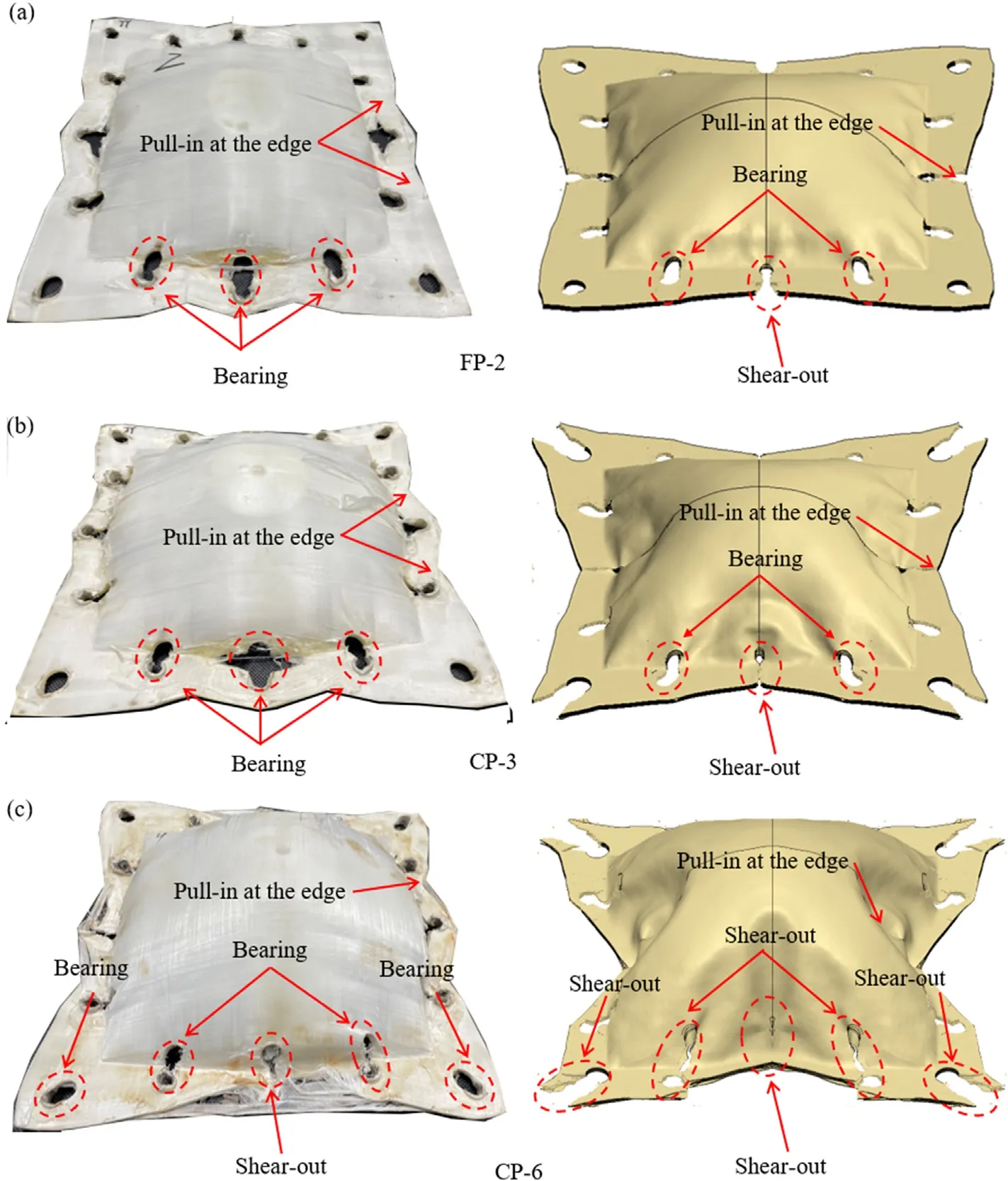
Fig.11.Comparison of experimental measured and numerically simulated failure modes of UHMWPE target impacted by(a)FP at 234 m/s,(b)CP at 219 m/s and(c)CP at 285 m/s.
Although the simulation model developed in the present study could reliably predict the residual velocity of the projectile and the maximum deflection of the target,another discrepancy was found between the simulation results and experimental observations,because the simulation of material failure around bolt holes at the clamped boundary was not perfect as previously discussed.In the simulation results (e.g.,Fig.11),increasing the impact velocity of projectile led to more severe failure of material around bolt holes at the four corners of the target,so that more material flowed toward the impacted area due to the weakening of boundary constraints:as a result,more obvious inward wrinkles formed around intermediate bolt holes at each edge(e.g.,CP-3 and CP-6).To widen the applicability of the simulation model,this issue would be squarely addressed in a future study.
Since the present continuum composite constitutive model not only ignored microscopic fiber structure and thermal softening effect of fibers but also simplified interlaminar interaction,the numerical simulation results could not perfectly match the experimental results.Nonetheless,overall,the present FE simulations were considered reasonable and acceptable.
4.Discussion
4.1.Deformation evolution of target under two kinds of loadings
In this section,the validated FE model was employed to compare the back face deflection (BFD) of a clamped UHMWPE plate impacted by CP at 234 m/s with that impacted by FP at the same velocity.The numerical evolution of the back profile for the exposed area was shown in Fig.12.The deflection induced by CP(mimicking combined blast and fragment loading)was consistently larger than that induced by FP(simulating blast loading alone).As the impact proceeded,the bulge deformation of the UHMWPE target born in its center gradually extended to the boundary.From Fig.12(a) and Fig.12(b),the CP-induced deformation reached the boundary at 150 μs,whereas that induced by FP was in the development until 200 us.Subsequently,as shown in Fig.12(c),the deflection at the boundary started to increase after 300 us,which was attributed to bearing/shear-out failures around bolt holes and the consequently insufficient boundary constraint.In Fig.12(c)and Fig.12(d),the CP-induced deflection was always larger than that caused by FP.The CP-and FP-induced deflections peaked and then started to rebound at around 1050 μs and 900 μs,respectively.

Fig.12.Numerically calculated evolutions of back face deflection at the exposed area of a clamped UHMWPE plate impacted separately by CP and FP,both at 234 m/s.
Consistent with experimental observation,when subjected to the impact of either CP or FP,the phenomenon of pull-in was numerically predicted in UHMWPE target plate.To quantify the pull-in effect under the two different kinds of impact loadings,three measuring points were arranged on the back face of the target,with vertical distances from the points to the impact center equaling 30,60,and 90 mm,respectively,as shown in Fig.13(a).For each measuring point,Fig.13(b) displayed the in-plane displacement along the vertical axisb,which could be taken as the pull-in displacement at that point.It was seen that using the composite projectile led to a more significant pull-in effect relative to the FP having the same impact velocity;correspondingly,the test sample experienced more severe failure at the boundary,as shown in Fig.6(b) for the case of CP-5.

Fig.13.Pull-in displacement of back face:(a)Arrangement of measuring points;(b)Evolution of pull-in displacement under two different kinds of impact loadings(CP versus FP).
4.2.Ballistic resistance of target under combined loading
In this section,the ballistic performance of clamped UHMWPE target subjected to impact loadings from two different projectiles,i.e.,FSP alone and composite projectile (CP),was investigated to reveal the underlying synergistic effect of combined loading.For comparison,the numerical results for impact with FSP alone and combined FSP-foam sabot,i.e.,CP impact,were presented in Fig.14.The ballistic limit of HA-792 UHMWPE target against CP impact increased by more than 30% compared to FSP impact alone,attributed mainly to the synergistic effect of foam sabot and FSP.Note that Δd=0 mm was selected for the plotting,which meant that the FSP and the Al foam sabot impacted the target simultaneously.
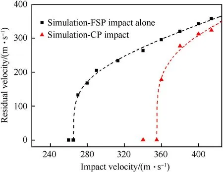
Fig.14.Ballistic performance of HA-792 UHMWPE plate: comparison between FSP impact alone and composite projectile (CP) impact.
Fig.15(a) illustrated how a clamped UHMWPE target plate changed its cross-sectional profile under CP impact at 313 m/s,while Fig.15(b)displayed the variation trend of its profile under FSP impact alone at the same velocity.Under CP impact,the dynamic response of the target plate due to FSP penetration was affected by the simultaneous strike of Al foam sabot,and hence was somewhat different from that under FSP impact alone.Specifically,at about 20 μs after the CP impact,the portion of target experiencing significant deformation was larger,for the diameter of foam sabot was considerably larger than that of the FSP;correspondingly,the BFD(back face deflection) was larger (5.8 mm versus 5.3 mm),indicating the Al foam sabot accelerated the out-of-plane motion of the target.The target experienced delamination failure under both CP and FSP impacts,but the delamination under CP impact occurred near its back face while that under FSP impact occurred closer to its front face.At about 40 μs after the CP impact,the out-of-plane acceleration of the target was intensified as a result of foam sabot strike,leading to a BFD of 11.0 mm;the corresponding BFD under FSP impact was only 9.4 mm.At about 60 μs after the CP impact,a global bulge of the target occurred,leading to enhanced membrane tension,less significant delamination and enlarged BFD of 15.3 mm,and hence weakened penetration effect of the FSP;Fig.15(a).In contrast,in the absence of foam sabot,the FSP was capable of penetrating through the target,the deformation became more localized,delamination failure was more severe,and the BFD of 13.4 mm was considerably less;Fig.15(b).In summary,for clamped UHMWPE targets studied here,the interaction between FSP and foam sabot that struck the target simultaneously acted to enhance the ballistic limit of the target.

Fig.15.Evolution of cross-sectional profile of clamped UHMWPE plate subjected to(a)simultaneous impact of FSP and foam sabot,and(b)FSP impact alone.Impact velocity fixed at 313 m/s.
Based upon the FE model,consider next the contact pressure between the FSP and the target plate.As shown in Fig.16(a),the peak contact pressure between the target and the FSP embedded in Al foam sabot was reduced by 10% compared to the case of FSP impact alone,as the increased target acceleration by the sabot reduced the relative movement between the FSP and target,leading to decreased interaction between the two.For the case of FSP impact alone,the contact pressure peaked and then dropped to zero once the perforation of the target occurred.In contrast,the FSP embedded in a CP continued to interact with the target till the relative velocity between the two took significantly more time to become null;Fig.16(a).
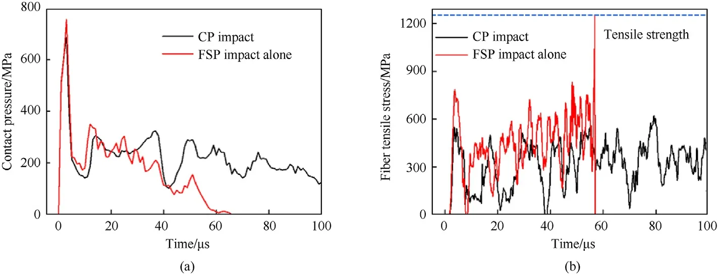
Fig.16.Comparison of UHMWPE laminate impacted by CP with that by FSP alone,both at 313 m/s:(a)Contact pressure between FSP and target;(b)Fiber tensile stress at the center of the back face.
Fig.16(b) compared the evolution of fiber tensile stress at the center of the back of the target under CP impact with that under FSP impact alone,both at a fixed velocity of 313 m/s.Under such conditions,the tensile stress induced by the FSP embedded in foam sabot never exceeded the strength threshold,while that induced by its counterpart(i.e.,FSP alone)reached the threshold at around 55 us.Again,this was attributed to the fact that the foam sabot had an accelerating effect on the target,thus reducing the relative velocity and interaction between it and the FSP.As previously discussed,due to the coupling effect between the two,the ballistic performance of UHMWPE target under CP impact was superior to that under FSP impact at the identical velocity.
4.3.Effect of the interval of arrival time between FSP and foam sabot
Upon varying the interval distance Δd(Fig.1(a)) between the FSP and the top surface of foam sabot,the arriving times of the FSP and the sabot on target could be altered.When Δd<0 mm,the FSP hit the target before the foam sabot,whereas the opposite held when Δd>0 mm.As the value of Δdgradually increased from negative to positive,the impulsive loading induced by foam sabot on the target was increasingly ahead of that generated by the FSP.How this would affect the ballistic performance of a clamped UHMWPE laminate was quantified using the FE model.The numerical results were presented in Fig.17 for-10 mm<Δd<20 mm in terms of the residual velocity of FSP,with the initial impact velocity of the CP fixed at 414 m/s and the thickness of UHMWPE laminate at 3 mm.As Δdwas increased,the ballistic resistance of UHMWPE laminate initially increased (i.e.,the residual velocity of FSP dropped),reaching a peak,and then started to decrease.For the case considered here,optimal performance (minimal residual velocity of FSP) of the target was realized at Δd=5 mm.

Fig.17.Numerically predicted residual velocity of FSP versus its spacing distance Δd in CP at the initial impact velocity of 414 m/s.The clamped UHMWPE target plate was 3 mm thick.
To explore the mechanisms underlying the influence of Δdon ballistic performance,the contact pressure between FSP and target as well as the maximum principal strain at the center of back face were plotted as functions of time in Fig.18(a) and Fig.18(b),respectively,with 0 μs representing the instant the impact of foam sabot on target was initiated.As shown in Fig.18(a),relative to the case of Δd=-10 mm,when the CP with Δd=5 mm hit the target,the contact pressure had a lower peak value and lasted longer before dropping to zero.This was attributed to the acceleration of target when it was hit by the foam sabot,which led to an enhanced ballistic limit,as discussed in the previous section.
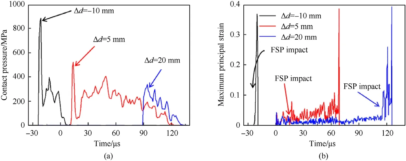
Fig.18.Mechanical response of clamped UHMWPE plate impacted by CP for selected values of Δd(-10 mm,5 mm and 20 mm):(a)evolution of contact pressure between FSP and the target,and(b)evolution of maximum principal strain at the center of back face(below the FSP).Time=0 μs corresponded to the moment when foam sabot started to hit the target.
In addition,to generate out-of-plane impact load on target,the foam sabot also caused the target to stretch in plane,thus affecting its strain state.The failure criterion based on maximum principal strain had been successfully employed to characterize the failure of UHMWPE composite subjected to blast loading [17].Thus,the maximum principal strain at the center of the back face of the target was used to describe its strain state under CP impact.As shown in Fig.18(b),as Δdwas increased from -10 mm via 5-20 mm,the maximum principal strain before the impact of FSP reached a value of 0,0.038 and 0.062,respectively,implying that increasing the Δdof FSP also increased strain levels in the target.Relative to the case of Δd=5 mm,the CP with Δd=20 mm led further drop in the contact pressure between FSP and target(Fig.18(a)),while the residual velocity of the FSP increased(Fig.17).For a CP with Δd=20 mm,the foam sabot impacted the target first,causing it to experience significant strain before the FSP started to penetrate it;Fig.18(b).Accordingly,the capacity of the target to absorb the impact energy of the FSP via bulging deformation was reduced and hence its ballistic performance was inferior.
In summary,the impulsive loading induced by a foam sabot housing the FSP could either enhance or reduce the ballistic resistance of a clamped UHMWPE target plate,depending on the variation of Δd.As Δdwas increased from negative to positive,the enhancing role of foam sabot gradually increased,reaching a peak,and then gradually decreased.Correspondingly,the ballistic performance of the target exhibited a similar variation trend.
5.Concluding remarks
The dynamic response of fully-clamped UHMWPE laminated plates under combined shock and fragment loading had been systematically investigated,both experimentally and numerically.The combined impact loading was achieved by launching a FSP-foam sabot composite projectile via a light-gas gun.Deformation and failure patterns were compared with those generated by foam projectile impact alone,and how the position of the FSP embedded in the foam sabot affected the ballistic performance of the target was quantified.The main conclusions were summarized as follows:
(i) Relative to blast loading induced by foam projectile alone,the combined blast and fragment loading led to larger back face deflection of the target plate and more severe failure near its clamped edges.
(ii) When the foam sabot and the FSP simultaneously hit the target,the former led to larger out-of-plane deformation(bulging),thus enhancing the ballistic resistance of the target.
(iii) The impulsive loading induced by a foam sabot housing the FSP could either enhance or reduce the ballistic resistance of a clamped UHMWPE target plate,depending critically on the distance between the FSP embedded in the foam sabot and the top surface of the latter.
(iv) When the blast loading and fragment impact arrived simultaneously at the target,its ballistic resistance was superior to that achieved when subjected to fragment impact alone,benefited from the accelerated movement of the target due to simultaneous blast loading.
The results presented in the current study are helpful for designing high-performance lightweight protective structures against combined blast and fragment loadings.
Declaration of competing interest
The authors declare that they have no known competing financial interests or personal relationships that could have appeared to influence the work reported in this paper.
Acknowledgment
This work was supported by the National Natural Science Foundation of China (Grant No.12032010,11902155 and 12072250),by the Natural Science Foundation of Jiangsu Province (Grant No.BK20190382),by the Research Fund of State Key Laboratory of Mechanics and Control of Mechanical Structures(Grant No.MCMS-I-0222K01),by the Fund of Prospective Layout of Scientific Research for NUAA,and by the Foundation for the Priority Academic Program Development of Jiangsu Higher Education Institutions.
杂志排行

Defence Technology的其它文章
- An energetic nano-fiber composite based on polystyrene and 1,3,5-trinitro-1,3,5-triazinane fabricated via electrospinning technique
- Aerial multi-spectral AI-based detection system for unexploded ordnance
- Model-based deep learning for fiber bundle infrared image restoration
- Robust design and analysis for opto-mechanical two array laser warning system
- Combustion behavior and mechanism of molecular perovskite energetic material DAP-4-based composites with metal fuel Al
- Perforation studies of concrete panel under high velocity projectile impact based on an improved dynamic constitutive model