Dissimilar welding of high nitrogen stainless steel and low alloy high strength steel under different shielding gas composition: Process,microstructure and mechanical properties
2023-10-09ZengLiuChengleiFnChunliYngZhuMingSnboLinLngpingWng
Zeng Liu ,Cheng-lei Fn ,* ,Chun-li Yng ,Zhu Ming ,Sn-bo Lin ,Lng-ping Wng
a State Key Laboratory of Advanced Welding and Joining,Harbin Institute of Technology,Harbin,150001,China
b Inner Mongolia Metal Material Research Institute,Yantai,264000,China
Keywords:High nitrogen steel Dissimilar steel joints Shielding gas Metal transfer Microstructure Mechanical properties
ABSTRACT Ar-N2-O2 ternary shielding gas is employed in dissimilar welding between high nitrogen steel and low alloy steel.The effect of O2 and N2 is investigated based on the systematical analysis of the metal transfer,nitrogen escape phenomenon,weld appearance,nondestructive detection,nitrogen content distribution,microstructure and mechanical properties.There are two nitrogen sources of the nitrogen in the weld:high nitrogen base material and shielding gas.The effect of shielding gas is mainly reflected in these two aspects.The change of the droplet transfer mode affects the fusion ratio,N2 in the shielding gas can increase nitrogen content and promote the nitrogen uniform distribution.The addition of 2% O2 to Ar matrix can change the metal transfer from globular transfer to spray transfer,high nitrogen base material is thereby dissolved more to the molten pool,making nitrogen content increase,ferrite decrease and the mechanical properties improve.When applying N2-containing shielding gas,arc stability becomes poor and short-circuiting transfer frequency increases due to the nitrogen escape from droplets and the molten pool.Performance of the joints is improved with N2 increasing,but internal gas pores are easier to appear because of the poor capacity of low alloy steel to dissolve nitrogen,The generation of pores will greatly reduce the impact resistance.4-8% N2 content in shielding gas is recommended in this study considering the integrated properties of the dissimilar welded joint.
1.Introduction
High nitrogen steel attracted widespread attention in recent years in the field of defense because of the remarkable strain rate strengthening effect [1],which has great potential to replace traditional medium carbon low alloy steel [2,3].However,oversaturated nitrogen in the steel would escape during the fusion welding process and restricts its application.A lot of researches on high nitrogen steel focuses on the weldability[4,5].Low alloy steel is also extensively used in defensive structures [6].The dissimilar welding of high nitrogen steel and low alloy steel has not been reported but the application is becoming more and more attractive with the development of high nitrogen steel.The application of N2-containing shielding gas has become an indispensable means to inhabit the nitrogen escape during high nitrogen steel welding process.On this basis,this study is to figure out whether the N2-shielding gas can play an active role in high nitrogen steel dissimilar welding and its effect on welded joints performance.
N2in the arc atmosphere plays an important role in increasing nitrogen content in the weld[7,8],nitrogen content increases with the N2pressure in the shielding gas [9] and the solidification of nitrogen can effectively reduce the ferrite in the austenitic weld[10,11].Paulraj et al.[12] used this feature to balance the microstructure of duplex weld.Researchers also applied the N2-containing shielding gas to improve the performance of the welded joints.Fouad et al.[13] added 2% N2in Ar to weld 316 stainless steels.The ultimate tensile strength and hardness were both increased and it was indicated that the tensile performance of the weld depends strongly on the heat input and nitrogen content in shielding gas.Kim et al.[14]applied Ar and Ar-5% N2to investigate the effect of N2on the resistance to pitting corrosion of duplex stainless-steel weld.The presence of N2in the shielding gas can increase the austenite content and can make the alloy elements such as chromium,nickel and molybdenum distributed more uniform.The pitting corrosion resistance of the material was thereby improved [15].In addition,the addition of nitrogen to the weld metal can also increase the pitting potential and the passivation current [16].Pamuk et al.[17] investigated the effect of Ar-N2backing ratios of microstructure and corrosion resistance of the weld.The base material is duplex stainless steel,the shielding gas is pure Ar.Nitrogen content in the weld and heat affected zone on root sides increased with the N2content in the backing gas.With the N2content increased,the nitrogen content of the heat affected zone increased firstly.The nitrogen content of the weld and the HAZ both reached the same level of the base material,and the highest corrosion resistance was obtained when using 100% N2as the backing gas.
N2content in the shielding gas is not the more the better,there is an optimal proportion range.Okagawa et al.[18] suggested N2content should be below 5% when welding 304 L.Yang et al.[19]stated that N2proportion should not be over 10% considering the welding pores and formation quality when applying N2-containing shielding gas to fabricate high nitrogen stainless steel.These indicates that the critical N2content has much to do with the type of the materials.The relationship between N2content and porosity in the weld is thereby complex,the addition of N2can inhibit the formation of gas pores in a certain range[20],but a large number of gas pores are generated when N2content is too high.Porosity formation is determined by composition of shielding gas,welding consumable and base material [21].The main role of N2in the shielding gas is to inhibit the escape of nitrogen in the molten pool so that the austenite content increases,the uniformity of the weld microstructure is improved[22].In summary,there are three major effects of N2-containing shielding gas:compensate for the nitrogen loss,adjust the phase proportion in the weld and improve the mechanical properties.However,most studies have not linked the nitrogen loss phenomenon during welding process and the nitrogen content in the weld with the microstructure and properties,which is very important in the welding of high nitrogen steel.
In this study,high nitrogen austenitic stainless steel and low alloy strength steel are weld with different shielding gas compositions to study the weldability of the dissimilar steel.The microstructure and the change of mechanical properties were connected with the welding process of metal transfer and nitrogen escape phenomenon to explain the effect of shielding gas composition on the dissimilar steel joints.The results can be a reference of dissimilar welding of high nitrogen steel with steels and the application of N2-containing shielding gas for steel arc welding.
2.Materials and methods
The base materials in this study are 7 mm thick plates of high nitrogen stainless steel (HNS) with nitrogen content of 0.65 wt% and high strength low alloy high strength steel (HSS).The dimensions of the HNS and HSS are both 150 × 100 × 7 mm3.A symmetrical single V groove was prepared with the angle of 60°.Chemical compositions of the base materials and filler material are shown in Table 1.ER 307Mo was selected as the filler material which is a typical austenitic steel filler that contains alloying elements such as Cr and Mn that can improve nitrogen solubility on the premise of no new chemical elements are introduced.The experimental design is presented in Table 2.Adding 2% O2can greatly improve the stability of the high nitrogen steel welding process and help to maintain the nitrogen content in the weld at a certain level[23].The O2content should not be too high,otherwise too much oxide is formed and there is a risk of oxygen pores.Three kinds of ternary shielding gas with different content of N2within 12% were adopted to investigate the effect of N2,higher N2 level would lead to a great risk of nitrogen gas pores.Pure Ar and 2% O2-98% Ar were taken as control groups,which can also be used to illustrate the role of O2.The shielding gas used in this study was all ordered from the Linde Group.

Table 1 Chemical compositions of the base and filler materials.

Table 2 Experimental design.
The welding power supply (Fornis TPS4000) was operated in direct current electrode positive (DCEP) mode.The Abb robot was used to control the movement of the torch.Before welding,the groove face was polished with angle grinder to 600 grind and then wiped with absolute ethanol.Table 3 shows the welding parameters.
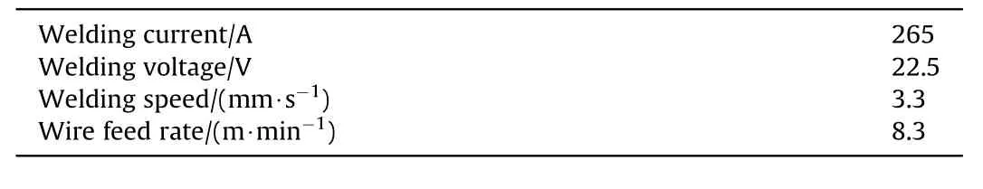
Table 3 Welding parameters.
Fig.1 shows the schematic of the position and the size of the specimens.Tensile test and impact test were conducted to evaluate the performance of the welded joints.Plate tensile test was used to measure the strength of the entire joints,rod tensile test was used to measure the strength of the strength near the weld junction.Similarly,in order to analyze the impact energy of the joints,the Charpy V-notch was made at three locations of weld center and bond area on both sides of the welds.Nitrogen content was measured by EltraONH-2000 hydrogen-oxygen-nitrogen analyzer.Seven specimens in different locations were made to characterize the distribution of nitrogen of the welded joints.In order to ensure the repeatability of the test results,three samples of the tensile test and the impact test were taken then averaged the results.Two pairs of plates were welded for each kind of shielding gas to guarantee the quantity of the samples taken.A Phantom-V311 high-speed camera was used to observe the metal transfer,the frame rate was 2000 frames per second.Keyence VHX-2000 digital microscope was used to obtain the microstructure of the welded joints and the fracture morphology.The phase composition was determined by Xray diffraction(XRD)(Bruker D8 ADVANCE)using Cu Kα radiation.Merlin compact scanning electron microscopy (SEM) with an energy dispersive spectrometer (EDS) was employed to analyze the chemical composition of the weld.
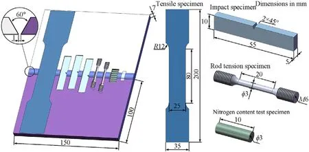
Fig.1.Schematic of the position and the size of the specimens.
3.Results and discussion
3.1.Welding process
Fig.2 shows the arc morphology and droplet transfer process with different shielding gas composition.The arc length decreased with the gas content added to the Ar matrix.The arc has a high temperature,the polyatomic gas will be decomposed into monatomic gas under the thermal effect of arc.The dissociation reaction is endothermic,which has a cooling effect on the arc.Therefore,adding some polyatomic gas to monatomic gas Ar can make the arc compressed and the arc length thereby becomes shorter.The droplet transfer with pure Ar is globular transfer.When adding 2% O2to the shielding gas,the metal transfer mode is changed into spray transfer because the active gas O2can effectively reduce the surface tension of the droplet.The degree to which the arc length became shorter was thereby more severe than adding N2subsequently,whose metal transfer mode all remains spray transfer.It is found that obvious nitrogen escape from the molten pool below the arc,which leads to welding spatter when N2content reached 8%.The bubbles escapes more vehemently from the molten pool with 12% N2shielding gas,the number of welding spatter thereby increases.
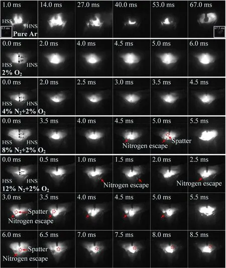
Fig.2.Droplet transfer process with different shielding gas composition.
The number of two 5-s droplet transfer and short-circuiting transfer of it was counted and then averaged the results shown in Fig.3,the frequency of droplet transfer increases sharply when adding 2% O2to Ar and then decreases with the N2content.The variation of the short-circuiting transfer presents the opposite tendency,whose frequency decreases when using binary shielding gas containing 2% O2and then increases with the added content of N2in the Ar-2% O2-N2ternary shielding gas.
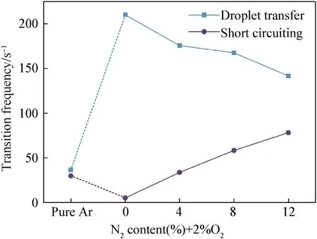
Fig.3.Transition frequency with different shielding gas composition.
The trend of the transition frequency can be used to reflect the droplet size and the welding stability.From Fig.2,the stability of the welding process was improved,and the arc was compressed significantly when adding 2% O2to Ar so that the transfer mode was changed.However,adding N2to the shielding gas reduced the transition frequency,which is contrary to the effect of arc compression caused by adding polyatomic gas.In addition,the frequency of the short circuiting increased obviously with the N2content in the shielding gas.All these show that the N2addition to the shielding gas make the welding stability decrease,which caused by nitrogen escape during the welding process and would be analyzed combined with the nitrogen escape phenomenon.
It was found that the size of the droplet changed significantly in a very short time during the droplet falling process of the shielding gas containing N2content of 8% and 12%.As shown in Fig.4(a),from 1.0 to 1.5 m,the droplet expanded.As shown in Fig.4(b),from 1.5 to 2.0 m,the droplet deflated,and it has an irregular shape.The period of 0.5 m is well below their average metal transfer cycle(about 6 m and 7 m).Considering the anomalous phenomena of the metal transfer has only been found in the metal transfer of the shielding gas containing higher N2content of 8% and 12%,it can be inferred that the abnormal expansion and shrinkage of the droplet are caused by the nitrogen behavior.This interesting phenomenon has been found in the observation of the metal transfer of the nitrogencontaining welding wire that nitrogen escape from the droplet caused the droplet expansion and fragmentation,as reported by Liu et al.(2021).Regarding the welding material with high nitrogen content,nitrogen escaped from the inside of the droplet because of the change of the nitrogen solubility during the melting process.As for the filler metal used in this study,there is no nitrogen in the material,the occurrence of the droplet expansion means that nitrogen in the shielding gas has dissolved into the droplet and escaped in a very short time.What’ more,it is quite possible that the dissolution of nitrogen has already occurred at the beginning of melting.As the 1.5 m shown in Fig.4(a),it is observed that the luminous region of arc expanding rapidly after the droplet bursting.This is due to the droplet bursting brings large amount of nitrogen to the arc atmosphere in a short time,which is one of the reasons of the N2-containg shielding gas worsens the welding process stability.The rapid expansion of the droplet can also make the occurrence of short circuiting,as 0.0-1.5 m shown in Fig.4(b),the droplet touched the molten pool in the process of continuous expansion.However,the droplet did not fall into the molten pool because of the irregular movement caused by nitrogen escape.
Not only from the droplet,nitrogen escape from the molten pool can also cause the short circuiting.Fig.5 shows two typical cases of the short circuiting caused by nitrogen escape from the molten pool.As the 1.0 m shown in Fig.5(a),the fluctuation and swell of the molten pool surface caused by nitrogen escape was in contact with the droplet that had not depart the welding wire would cause the short circuiting;besides,as the 0.5-2.0 m shown in Fig.5(b),the blow force of the bubble burst from the molten pool could change the movement of the droplet and hinder the droplet transfer.The size of the droplet thereby became bigger,which resulted in the short circuiting.

Fig.5.Short circuiting caused by nitrogen escape with the shielding gas of 12% N2-2% O2-86% Ar.
Fig.6 shows the morphology of the molten pool with different shielding gas.It is found that the obvious bubble escape in the molten pool with the N2content of 8% and 12%.The number of bubbles escaping from the molten pool of 12% N2-2% O2-86% Ar shielding gas is greater than 8% N2-2% O2-86% Ar.
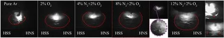
Fig.6.Morphology of molten pool with different shielding gas composition.
3.2.Gas pores and nitrogen content
Fig.7 shows the weld appearance and nondestructive detection of the joints with different shielding gas composition.Many small gas pores appeared in the weld when the N2content reach 8% and big surface gas pores appeared in the first half of the weld when the N2content reach 12%,even caused the bulges in the center of the weld.It is conceivable that if the nitrogen content continues to increase,the number and size of macroscopic pores will further increase,which shows that the N2range selected in this study is reasonable.It is also found some gas pores close to the base material of HNS in the weld.
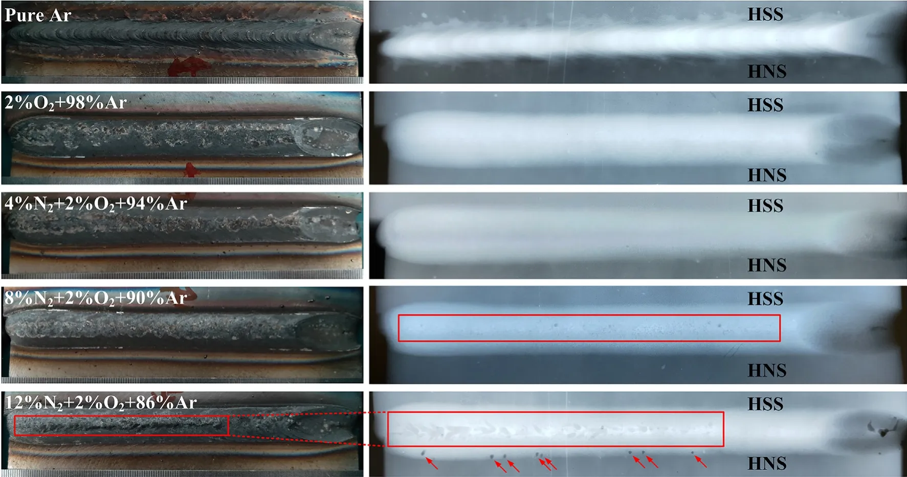
Fig.7.Weld appearance and nondestructive detection of the joints with different shielding gas composition.
Fig.8 shows the cross-section morphology of the joints with different shielding gas composition.The macroscopic gas pores appeared when N2content reached 8% and the pores are mainly distributed at the top of the weld.Interior pores are found in the weld with 12% N2-2% O2-86% Ar as shown in Fig.8(e).No surface pores are observed in the weld,but the surface of the weld is concave,which can be considered as a trace of the bubble bursting.As shown in Fig.8(f),the variation of the weld width(w1)with the shielding gas composition has a similar tendency with the variation tendency of droplet transfer frequency as shown in Fig.3.This is because the smaller the short-circuiting frequency,the longer the existence time of the arc,the weld width is thereby increased.Arc compression is another reason for the weld width narrowed and due to the deepening of the heat,the weld width at half of the weld(w2)increases with the N2content in the shielding gas.With the N2increasing,w1decreases while w2increases,indicating a continuous increase in fusion ratio.Using the center of the root gap as the center of the weld to measure the width between the weld toes on both sides to the center,it is found that the melting width of both sides is unequal,the melting width of the side of HNS is greater than HSS,but this situation is improved when the N2content reached 12%,which is because the arc energy becomes concentrated caused by arc compression.
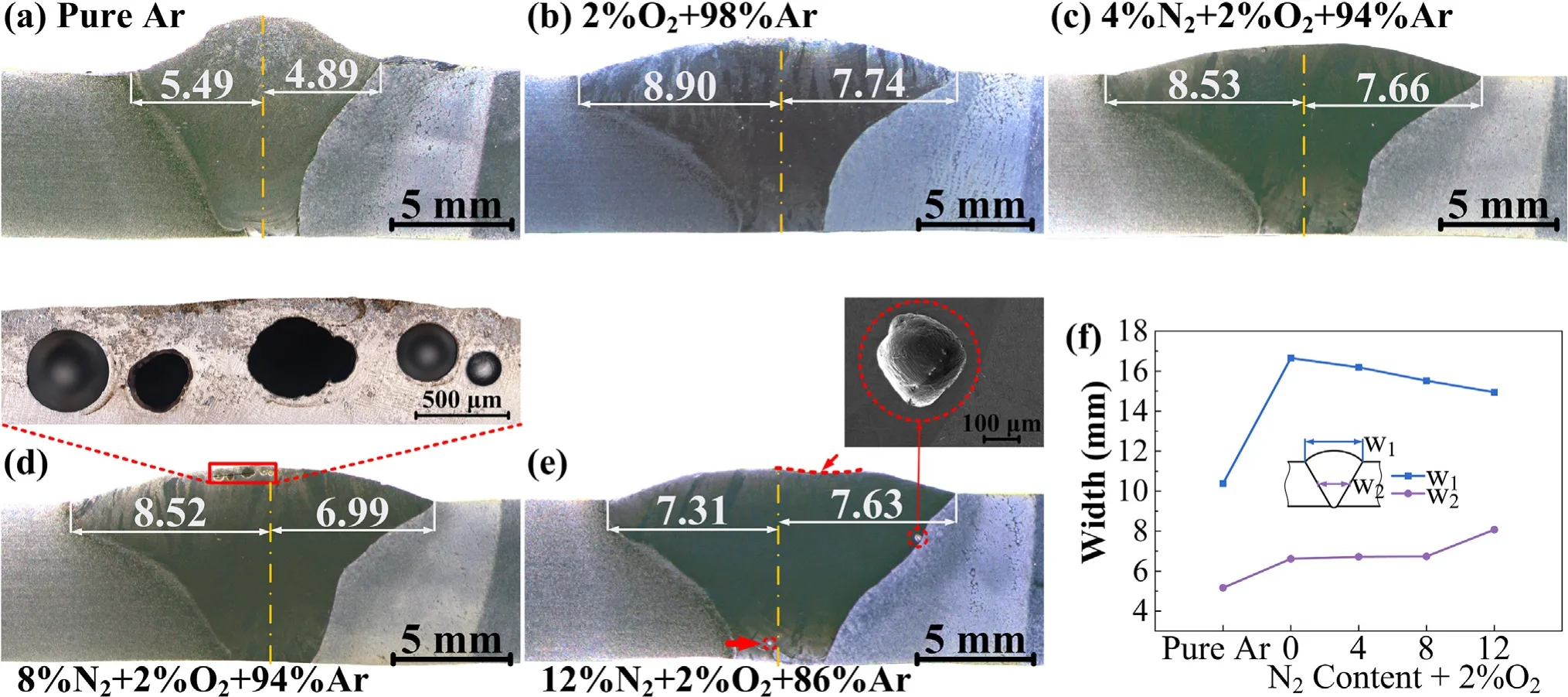
Fig.8.(a)-(e) Cross section morphology of the joints and (f) Weld width with different shielding gas composition.
In order to investigate the formation of the gas pores in the dissimilar steel weld,under the same welding process,the same kind of steel was welded with 12% N2-2% O2-86% Ar shielding gas.Fig.9 shows the weld appearance and nondestructive detection of the similar joints.Gas pores appeared in the center of both the welded joints.In the HNS-HNS joint,gas pores just appeared in the in the first half of the weld and the size of the pores become smaller with the welding process proceeding.In the HSS-HSS joint,gas pores exist in the entire weld and most of them are surface pores which caused the bulges in the weld.It is interesting that the existence and distribution of the gas pores in the dissimilar welded joints seems to be a combination of that in the two kinds of similar joints.Fig.10 shows the cross-section morphology of the same joints with the shielding gas of 12% N2-2% O2-86% Ar.It is observed that macroscopic pores are distributed on the top of the weld closed to the surface.The gas pores of the HSS-HSS weld with 12% N2-2% O2-86% Ar is larger and more concentrated than the weld of HNS-HNS,which also proves directly that the bulges are caused by the surface gas pores.
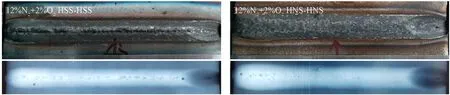
Fig.9.Weld appearance and nondestructive detection of the same joints with the shielding gas of 12% N2-2% O2-86% Ar.
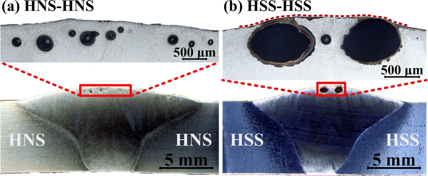
Fig.10.Cross section morphology of the same joints with the shielding gas of 12% N2-2% O2-86% Ar.
In the HNS-HSS dissimilar weld with N2-containing shielding gas and in the condition of using nitrogen-free filler metal,the weld has two sources of nitrogen of the weld: base material of high nitrogen steel and the shielding gas,which are the sources of nitrogen gas pores.Fig.11 shows the nitrogen content in the different position of the dissimilar welded joints with different shielding gas composition.From the base material of HNS to HSS,the nitrogen content of the joint with pure Ar decreased most rapidly.This is because the metal transfer mode of it was droplet transfer,the droplet size is big and accompanied by short circuiting.The existence time of the molten pool is short so that the time for nitrogen to dissolve and diffuse is short.The distribution trend of nitrogen in the other welded joints is similar,the nitrogen content in the center of the weld with N2-containing shielding gas in higher than that with 2% O2-98% Ar.However,the difference of nitrogen content in the weld center among the welded joints with N2-containing shielding gas is not obvious.The nitrogen content in the position close to the base material of HSS of the weld with 12% N2is noticeably higher than other welded joints.N2added in the shielding gas during the welding process can accelerate the nitrogen dissolution into the molten pool through the surface and suppress the nitrogen escape from the inside.What’ more,the fusion ratio increases with the N2content.Both of these will increase the nitrogen of the weld.However,the nitrogen content in the center of the weld was not increased obviously with N2content increasing,which is because the solubility of nitrogen is limited by the content and variety of chemical elements of the molten pool.In addition,as the metal transfer shown in Fig.2,the escape of nitrogen bubbles and welding spatter become violent when N2content in the shielding gas exceeded 8%.All of this means the nitrogen content in the weld has reached the capacity to dissolve nitrogen.The excess nitrogen will escape in the form of bubbles.Until the size and number of bubbles increase to the limit that can escape,the bubbles will remine in the weld to form pores.When the N2content reached 12%,the nitrogen content in the weld close to the base material of HSS increased greatly indicates the N2in the shielding gas promotes nitrogen element diffusion in the molten pool.

Fig.11.Nitrogen distribution of the joints with different shielding gas composition.
Base on the analysis of the gas pores and the variation of nitrogen content of HNS-HSS dissimilar weld,there are three main reasons for the formation of gas pores with N2-containing shielding gas: 1) the nitrogen content of the molten pool increases with the N2content in the shielding gas,the gas pores appear when the nitrogen content exceeds the capacity of the molten pool to dissolve nitrogen;2) the increase in nitrogen content of the entire molten pool inhibits the dissolution of nitrogen from the base material of HNS into the molten pool,the supersaturated nitrogen could not be dissolved by the molten pool and 3) the chemical elements that enhance the nitrogen solubility would be diluted with the dissolution of the base material of HSS.
What’s more,the distribution of the gas pores also has the relationship with the solidification of the molten pool,the gas pores caused by N2-containing shielding gas are mainly distributed at the top of the weld.With adding N2,nitrogen dissolves from the surface of the molten pool.The redundant nitrogen of the molten pool with shielding gas containing higher N2content that cannot dissolve into the molten metal would accumulate and become pores.It is indicated in Fig.6 that the escape of the gas pores occurred in the molten pool with the shielding gas containing high N2content,and the bubbles in the molten pool with 12% N2escaped more violently than 8% N2,which corresponds to the size and quantity of gas pores of the weld with 12% N2is greater than 8%.As the welding process proceeding,the porosity has a decreasing trend,which because that nitrogen exists near the surface and escapes to the atmosphere easily.It is inferred that the heat accumulated on the base material during the welding process would slow down the solidification of the molten pool and promotes the evolution of nitrogen.When employing 12% N2-2% O2-86% Ar shielding gas,the surface pores that caused bulges appeared in both the HSS-HSS weld and the HNS-HSS weld,but the difference is that the pores of the HNS-HSS weld are mainly distributed in the first half of the weld,which is similar to the weld of HNS-HNS with 12% N2,which indicates that the HNS base material of the dissimilar joints has slowed down the solidification of the molten pool because the thermal conductance of HNS is obviously worse than HSS.The pores exist in the entire weld of HSS-HSS with 12% N2shielding gas because the thermal conductance of HSS is good so that the solidification of the molten pool is rapid,which confirms the statement that the solidification rate has an effect on the distribution of gas pores in the weld.Therefore,reducing the solidification rate such as reducing the welding speed or adding the procedure of preheating can be used to reduce the porosity caused by employing N2-containing shielding gas.
3.3.Microstructure
Fig.12 shows the phase compositions of the welds with different shielding gas compositions determined by XRD.Ferrite is only found in the welds with pure Ar and 2% O2-98% Ar.The welds with N2-containing shielding gas are full austenitic.

Fig.12.XRD patterns of the weld center with different shielding compositions.
Fig.13 and Fig.14 show the macro-metallograph and microstructure of the joints with different shielding gas composition.The microstructure of the weld with pure Ar is skeletal ferrite distributed on the austenite matrix.When using 2% O2-98% Ar shielding gas,the content of ferrite was reduced significantly.The ferrite content in the weld is determined by calculating the proportion of the pixels of ferrite to the total number of pixels of the weld.The ferrite content of the weld with pure Ar and 2% O2-98% Ar are 41.7% and 2.0%,respectively.When N2is further added to the shielding gas,even for the N2content of 4%,the ferrite disappeared completely in the weld.When the N2content reached 8%,the ferrite content in the HAZ of the base material of HNS decreased obviously as presented in Fig.14 (g).

Fig.14.Microsturcture of the joints with different shielding gas composition.
Fig.8 shows the melting width of the base material of HNS is increased more than HSS after adding 2% O2to the Ar matrix,which indicates the base material of HNS dissolved more than HSS.As the nitrogen content variation shown in Fig.11,the increase of nitrogen content of the weld with 2% O2-98% Ar shielding gas is also caused by the dissolution of the base material of HNS.Because nitrogen is a strong austenitic forming element,the decrease of ferrite content can also be explained by the nitrogen content in the weld was increased.The phase composition of the welds with the N2-containing shielding gas are both the full austenitic weld,which is because the nitrogen content in the welds does not show obvious difference.However,as shown in Fig.11,the nitrogen content of the weld with 12% N2near the HSS side is obviously higher than other welds.The nitrogen solubility of HSS is very limited,so the increase in nitrogen content in that position may be one of the main reasons for the formation of interior gas pores.In order to further illustrate the influence of the dissolution of the base materials,detailed observation by SEM and EDS analysis of the welds are given in Fig.15.Micropores are observed in the welds with N2-containing shielding gas and it is also found a phenomenon that 3 or 4 gas pores are arranged in a straight line,which is the trace of the gas pores floating up.It gives another evidence that the source of the surface pores is not only from the N2-containing shielding gas,but also from the inside of the weld.The risk of the pores formation and the difficulty of nitrogen pores escape both increase with the N2content in the shielding gas.The change of chemical composition with shielding gas composition is summarized in Fig.15(f).The Ni content of filler metal is higher than the two base materials,so Ni content continues to decrease with the increase of fusion ratio.The Cr content in HNS and filler metal is similar,the decrease of Cr in the weld is caused by the dissolution of HSS.The Mn content increases first then decreases with the change of the shielding gas composition,which can be used to compare the effect of the two base materials because the Mn content of HNS is higher than the filler metal while Mn in HSS is lower.The increase of Mn indicates the effect of HNS is bigger than HSS,otherwise the effect of HSS is bigger.The Cr,Mn content decrease when N2content reached 8% because of more HSS dissolved into the weld,Fe content increases correspondingly.This situation is aggravated when N2reached 12%.Cr and Mn are both the alloying elements that can improve the nitrogen solubility.The increase of porosity is also related to the decrease of this kind of alloying elements caused by the dissolution of HSS.

Fig.15.(a)-(e) Microstructure of the welds and the chemical compositions of the weld and (f) Change of the chemical compositions with the shielding gas compositions.
The dissolution of HSS increases significantly when N2content reached 12% based on the above analysis.The chemical compositions between the filler metal and HSS vary greatly,macrosegregation is easier to appear when HSS dissolves more.As shown in Fig.16(a),macro-segregation appeared at the bottom of the weld,a macropore is found near the macro-segregation as the red arrow marked in Fig.8(e) and Fig.16(a).Obvious element diffusion occurs at the edge of the macro-segregation as the EDS line scanning shown in Fig.16(c).Nitrogen is easier to dissolve into the macro-segregation because the nitrogen atom is smaller,the nitrogen solubility of that is very low,which is also the source of the welding pores.As shown in Fig.16(d) and Fig.16(e),some micropores are found in the island macro-segregation,and the number of the gas pores in the upper half is obviously more than the below because of the rise of the bubbles.It is reasonable to infer that the macropore in Fig.16(a) is generated from the macro-segregation,floated faster and appeared in the weld as the molten pool flow.

Fig.16.Macro-segregation in the weld with 12% N2-2% O2-86% Ar.
3.4.Mechanical properties
Fig.17 shows the relationship between the impact energy and the shielding gas composition in both the bond areas and the center of the weld.The impact energy increases in the order of HSS bond area,weld metal and HNS bond area.In the position of the HSS bond area and weld metal,the impact energy does not present any trends with the change of the shielding gas composition.The impact energy of the HNS bond area increases obviously when adding 2% O2to the Ar matrix and continue to increase with the addition of N2,but when the N2content reached 12%,the impact energy decreases significantly,which indicates the N2in shielding gas mainly influences the impact energy of the bond area between the weld and the HNS base material.
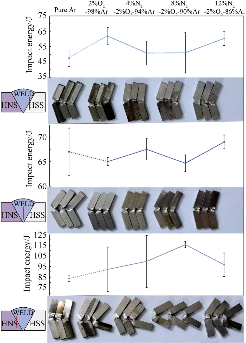
Fig.17.Impact energy of the welded joints.
The impact fracture of the bond area between the weld and HNS are given in Fig.18.The bond area is a heterogeneous position that contains the weld metal,the interface and the heat affect zone.From the macroscopic morphology of the fracture of the impact specimens,the fracture feature is not like the conventional impact fracture that contains two shear lips distributed on both sides symmetrically.Because of the difference in impact resistance,there is only one shear lip,and the fracture is along the weld junction and the area of the shear lip increases with N2in the shielding gas.When N2reached 8%,the fracture morphology changed obviously and two shear lips appeared,indicating that the impact resistance of this position is significantly improved.What’ more,the fracture of the impact specimen with pure Ar has a large proportion of flat area,which is the trace of tearing occurred during the impact.With the application of the multiple shielding gas,the tearing region gets smaller,and the region of dimples becomes larger.When N2reached 8%,the tearing region disappeared and replaced by dimples.
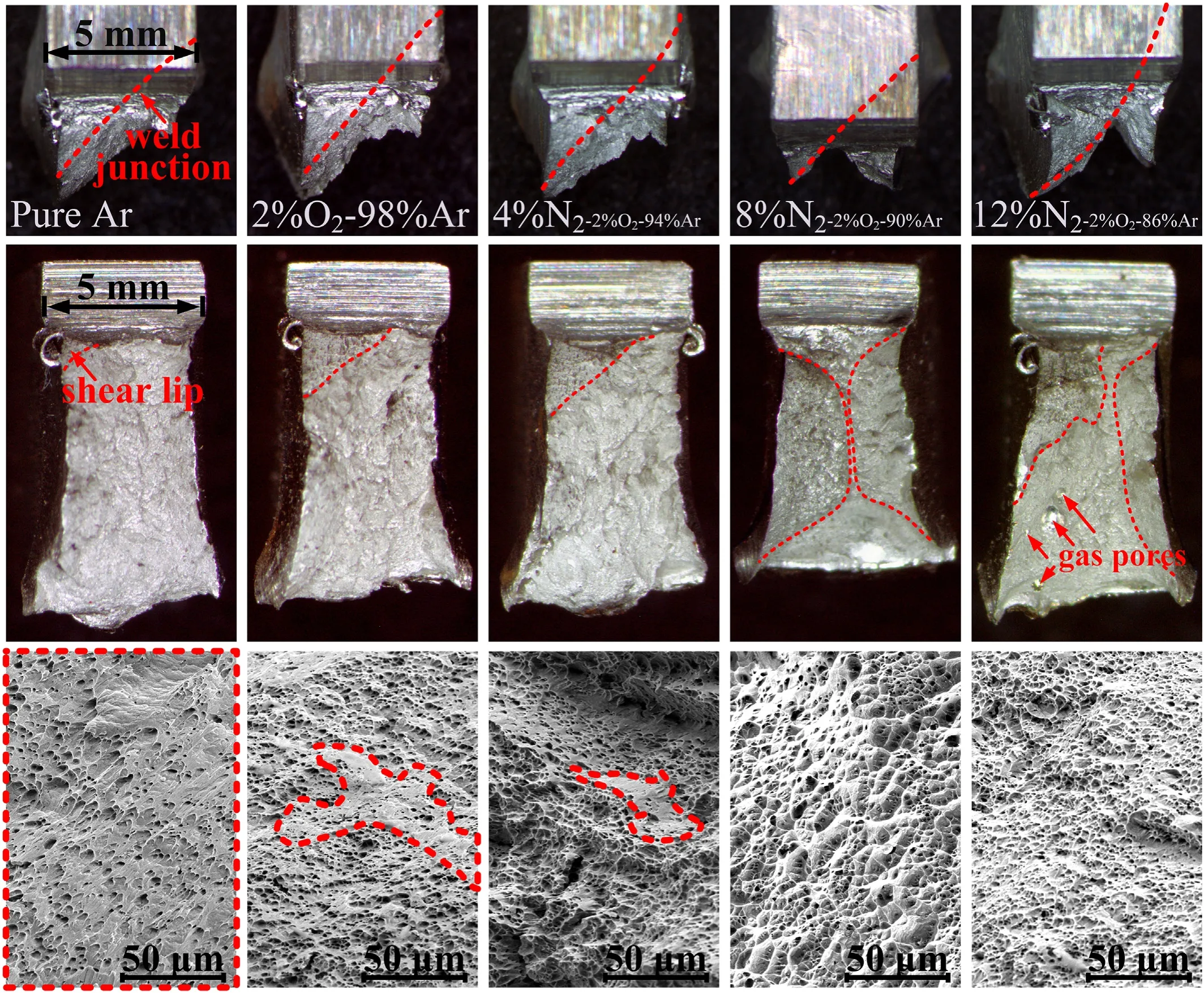
Fig.18.Morphology of the impact fracture.
The impact energy decreased obviously when N2reached 12%,the generation of the gas pores is the main reason of the impact resistance decrease.As shown in Fig.18 and Fig.19,it can be found that there is a tearing region around the gas pores,while the other region without gas pores is dimples morphology,which indicates that the existence of the welding pores causes the metal around the pores to tear apart during the impact.It can also be seen from the fracture morphology that tearing region appears around the gas pores and the cracks are easily to propagate along the tearing direction,as summarized in Fig.19(e),the crack propagation is directional the in the process of being impacted,and the existence of pores promotes the cracks propagation,even the pores themselves can be as the crack source,which is the reason why the pores greatly reduce the impact toughness.
Fig.20(a) shows the change of the tensile properties of welded joints.The tensile strength increased obviously with the N2content in the shielding gas.It is found that the fracture position on the surface is similar,as shown in Fig.20(b),the fracture positions of the front side of the welds are all close to HSS base material and that of the back side are all close to HNS base material.In order to explain the phenomena,Fig.20(c) gives the tensile strength near the bond area of both sides,although the change trend of the test results is consistent with the tensile strength,the strength of the bond area between HNS and weld is higher than that between HSS and weld,except for the joint with the shielding gas of pure Ar,which the two are almost equal.

Fig.20.Tensile properties of welded joints:(a)Tensile strength and elongation of the joints;(b)Fraction location of the tensile specimens;(c)Tensile strength near bond area on both sides.
The cross-section microstructure of the fracture was observed.Fig.21 shows the fracture cross section of the welded joint with pure Ar and 2% O2-98% Ar.The fracture of the pure Ar joint is irregular (Fig.21(a)),the crack develops along the ferrite and austerity phase boundary,especially along the interface of austenite and primary dendritic crystals (Fig.21(b)).The fracture surface of the joint with 2% O2-98% Ar becomes smooth(Fig.21(c))with ferrite content decreasing,but ferrite is found in the edge of the fracture and zigzag position(Fig.21(d)),which confirms the statement that the fracture is prone to occur in the position ferrite exists.As shown in Fig.21(e),the crack in the weld root of the HNS side broke along the fusion line flatly,which can be considered as one of the crack sources.It can be seen from it that the disordered ferrite distributed along the fusion line not only decrease the impact performance,but also affect the tensile performance.In addition,it is also found there are notch(Fig.21(f))and cracks(Fig.21(g)) in the weld root of the HSS side,which fractured along the fusion line and austenite dendrite respectively,indicating that this location is also the weak area of the joint.

Fig.21.Fracture cross section of the welded joint with pure Ar and 2% O2-98% Ar.
Fig.22 shows the tensile fracture location and microstructure of the joints with N2-containing shielding gas.It can be seen the fracture locations of the three joints are similar,the fracture position inside the weld is also similar that all are 3-5 mm away from the fusion line of the HSS base material and broke along the position almost parallel to the fusion line.As the schematic diagram shown in Fig.22(f),the fracture position is coincident with the solidification center of the weld,and as shown in Fig.22(d),the fracture extended either along or perpendicular to the dendrites.Thus,it can be seen that the uneven solidification coupled with the full austenitic weld make the fracture propagates smoothly along the grain boundary of the solidification center during the tensile process.It is also found that the deformation degree of the weld close to the HNS side is larger than that close to the HSS side,as shown in Fig.21(a),Fig.21(c)and Fig.22(e),cracks are also found in the HAZ of the HSS base material near the fusion line.The poor deformation capacity of HSS base metal limits the tensile performance of the dissimilar joint.

Fig.22.Fracture cross section of the welded joint with N2-containing shielding gas.
4.Conclusions
In this study,dissimilar steel of high nitrogen austenitic stainless steel and low alloy high strength martensitic steel were welded under the shielding gas of pure Ar,Ar-2% O2binary shielding gas and Ar-N2-2% O2ternary shielding gas with different N2content.The conclusions are as follows:
(1) The addition of O2to the Ar matrix shielding gas has a great influence on the droplet transfer mode.The change from globular transfer to spay transfer causes stability and existence time of arc improved,more high nitrogen stainless steel base material is thereby melted into the weld,making ferrite decreased significantly.
(2) After adding N2to the shielding gas,the arc is compressed,but the transition frequency decreases and the shortcircuiting transfer frequency increases with N2increasing,which can be explain from four aspects: expansion of the droplets,recoil caused by nitrogen bubbles burst in the molten pool,spatter from nitrogen escape and reduction of the arc space.
(3) The shielding gas induced gas pores mainly concentrated in the top of the weld and has relationship with the solidification influenced by the state of the base material.From this it can be inferred that the application of preheating and postheating can help to improve this kind of gas pores.
(4) N2in the shielding gas can suppress the escape of nitrogen and promote the uniform of nitrogen distribution in the whole joint,including the weld region near the low alloy steel with poor ability to dissolve nitrogen,which is the main reason of the generation of internal porosity in the weld with 12% N2.
(5) The dissimilar joint with 8% N2content has the best integrated properties.4-8% N2is recommended to be added in the shielding gas when welding high nitrogen steel and low alloy steel weld.
Declaration of competing interest
The authors declare that they have no known competing financial interests or personal relationships that could have appeared to influence the work reported in this paper.
杂志排行

Defence Technology的其它文章
- An energetic nano-fiber composite based on polystyrene and 1,3,5-trinitro-1,3,5-triazinane fabricated via electrospinning technique
- Dynamic response of UHMWPE plates under combined shock and fragment loading
- Aerial multi-spectral AI-based detection system for unexploded ordnance
- Model-based deep learning for fiber bundle infrared image restoration
- Robust design and analysis for opto-mechanical two array laser warning system
- Combustion behavior and mechanism of molecular perovskite energetic material DAP-4-based composites with metal fuel Al