The damage to model concrete gravity dams subjected to water explosions
2023-10-09ShangMaYeqingChenZhenqingWangShutaoLiQingZhuLongmingChen
Shang Ma ,Ye-qing Chen ,Zhen-qing Wang ,Shu-tao Li ,** ,Qing Zhu ,Long-ming Chen
a College of Aerospace and Civil Engineering,Harbin Engineering University,Harbin,150001,China
b Institute of Defense Engineering,AMS,PLA,Beijing,100036,China
Keywords:Underwater explosion Concrete gravity dam Model test Damage evolution
ABSTRACT Over the past century,the safety of dams has gradually attracted attention from all parties.Research on the dynamic response and damage evolution of dams under extreme loads is the basis of dam safety issues.In recent decades,scholars have studied the responses of dams under earthquake loads,but there is still much room for improvement in experimental and theoretical research on small probability loads such as explosions.In this paper,a 50-m-high concrete gravity dam is used as a prototype dam,and a water explosion model test of a 2.5-m-high concrete gravity dam is designed.The water pressure and the acceleration response of the dam body in the test are analysed.The pressure characteristics and dynamic response of the dam body are assessed.Taking the dam damage test as an example,a numerical model of concrete gravity dam damage is established,and the damage evolution of the dam body is analysed.By combining experiments and numerical simulations,the damage characteristics of the dam body under the action of different charge water explosions are clarified.The integrity of the dam body is well maintained under the action of a small-quantity water explosion,and the dynamic response of the dam body is mainly caused by the shock wave.Both the shock wave and the bubble pulsation cause the dam body to accelerate,and the peak acceleration of the dam body under the action of the bubble pulsation is only one percent of the peak acceleration of the dam body under the action of the shock wave.When subjected to explosions in large quantities of water,the dam body is seriously damaged.Under the action of a shock wave,the dam body produces a secondary acceleration response,which is generated by an internal interaction after the dam body is damaged.The damage evolution process of the dam body under the action of a large-scale water explosion is analysed,and it is found that the shock wave pressure of the water explosion causes local damage to the dam body facing the explosion.After the peak value of the shock wave,the impulse continues to act on the dam body,causing cumulative damage and damage inside the dam body.
1.Introduction
With global developments and rampant terrorist attacks,increasing attention has been given to the protection and safety of large buildings.As an important hydraulic structure,various countries have successively carried out research on dams subjected to explosive loads.In July 1946,the United States conducted several underwater explosion tests of nuclear bombs on Bikini Island [1],and since 1953,the Army Corps of Engineers Test Station has been asked to study the dynamic response and damage mode of dams subjected to explosion loads.During World War II,British scientist Wallis conducted theoretical and experimental research on underwater explosions.Using the results of this research,the British army successfully blew up the Mohne dam and the Eder dam in Germany [2].In the early 1950s,the former Soviet Union also conducted systematic experimental studies on the responses of dams to underwater explosions[3].France has formulated a special dam safety law,stipulating that all large reservoirs must conduct dam-break model test studies.
The experimental study of underwater explosions began in 1948,when Cole [4] analysed the physical and chemical phenomena of underwater explosions,the characteristics of shock wave propagation in water,and the bubble pulsation involved in underwater explosions.The law of the peak pressure of the shock wave and the characteristics of shock wave propagation in underwater explosions were summarized,and a corresponding calculation formula was offered.This has created a precedent for systematically studying the dynamic phenomena of underwater explosions.Slifko[5]conducted in-depth experimental research on the pressure characteristics of explosion shock waves in an infinite water medium and revealed the relationships among underwater shock wave pressure,water depth and other factors.
The underwater testing of large-scale explosives is restricted by objective factors such as the environment.Researchers generally use small-scaled model tests to study the typical dynamic behaviour of underwater explosions[6,7].Hung[8]used a charge with a TNT equivalent of 1.12 g to conduct experiments and studied the behaviour of underwater explosion bubbles at different boundaries.It was found that the bubbles formed by the underwater explosion of microcharges contracted slightly faster than the electric spark/laser bubbles.A centrifuge generated centrifugal force through high-speed rotation so that the model had a gravitational field environment similar to that of the prototype.Snay[9,10]noted that in an underwater explosion scale test,the Coriolis force caused by the rotation of the centrifuge had a negligible effect on the bubble movement.Using a centrifuge test facility,Price[11]conducted an underwater explosion test of a small structure under an acceleration of 190 g and replicated the conditions required for a large-scale structural response of the prototype.To explore the dynamic and complex behaviour of underwater explosions,Gong [12] used a centrifuge scale model test to study the behaviour characteristics of underwater explosions based on the dimensional similarity ratio,revealing that the scale factor of bubbles is different from that of time.Hu[13]and Long[14]conducted a centrifuge scale-down test of the dynamic response of a steel plate structure in an underwater explosion.The test confirmed that the shock wave was slightly affected by the speed of the centrifuge,and the deformation of the steel plate structure caused by bubble pulsation could not be ignored.Song[15]discussed the applicability of the reduction ratio to the dynamic load of an underwater explosion by numerical simulation of the centrifugal underwater explosion scale test.Wang[16] studied the law of underwater explosion shock waves and bubble pulsation in a centrifuge using a scale model test.Based on the similarity rate criterion of underwater explosion loads,Vanadit-Ellis and Davis[3]believed that a centrifuge could not only simulate the internal stress state of a gravity dam and the tested fluid pressure but also simulate the bubble pulse load of an underwater explosion and the peak pressure of the shock wave propagation.A 1/100 model was developed,the response of a concrete dam subjected to an underwater explosion was tested by the centrifuge test,and the failure mode of the gravity dam was obtained.Lu [17-20]established a physical model,used the mechanical impact of a drop weight to simulate a shock wave in an underwater explosion,carried out experimental research on the damage and protection of the concrete gravity dam under the action of the shock wave,and analysed the load propagation of the underwater explosion in medium and far fields.At the front of the dam,this can be equivalent to a plane wave acting on the dam body.However,it is impossible to simulate the bubble pulsation pressure,cavitation and jet effect of an underwater explosion with a heavy hammer impact,and it is difficult to truly reflect the dynamic response and failure mode of a dam subjected to an explosion.
Researchers have conducted numerical simulations on the damage mode of concrete gravity dams subjected to water explosions.Wang [21] used a finite element numerical simulation to discuss the stability of concrete gravity dam foundations subjected to water explosions.The foundation performance has a great influence on the shock wave propagation in the dam and the damage to the dam body.Shu [22] discussed the failure mode of concrete gravity dams subjected to penetrating strikes,discussed the destructive effects of explosions on the dam body after the projectile penetrated the dam body,and classified the dam body penetration failure modes.Wang et al.[23] discussed the damage classification of concrete gravity dams subjected to near-field water explosions using a fluid-structure coupling algorithm and proposed a vibration-based damage assessment method to rate and classify the damage status of dams after explosions.Zhu et al.[24] summarized and classified the failure modes of concrete gravity dams under the action of water explosions and discussed the damage characteristics of concrete gravity dams under the action of water explosions with different charges by using a joint ABAQUS and LSDYNA modelling method.Wang [25] analysed the damage characteristics of a dam body subjected to a water explosion under the premise of considering the initial stress field of the gravity dam and considered that the safety of the dam foundation is a key factor to be considered in research on explosion-resistant dam bodies.Liu[26] obtained the main frequency and basic mode shape of a dam body through numerical calculation by inverting the material parameters of the dam body during water explosions.The numerical research on the dynamic response and failure of gravity dams under the action of water explosions has mainly focused on the classification and influencing factors of dam body failure modes.
Centrifuge tests have stringent instrument and equipment requirements and can only be carried out in a centrifuge test chamber.The model is limited to a certain size,and the constraints are relatively simple.Only a small number of underwater explosion tests can be carried out.For a structure,the scale of a centrifuge test is too small;a concrete gravity dam exhibits a highly nonlinear behaviour state under the action of an explosion and the influence of boundary effects.A centrifuge scale model test will not necessarily show the damage to a concrete gravity dam subjected to an underwater explosion.Therefore,large-scale testing is essential.The damage test of a large-scale concrete gravity dam under the action of an underwater explosion can avoid the influence of the size effect,and a multiple-section test can determine the specific influence of the dam body joint on the dynamic response of the dam section.
In explosion tests,the instantaneous acceleration of a concrete gravity dam under the action of an underwater explosion can reach several thousand gravitational accelerations,which is much larger than the maximum value that can be provided in a centrifuge test.Therefore,the additional acceleration of the structure can be temporarily ignored,and only the effect of the load generated by the explosion on the structure is considered.On this basis,based on certain experimental assumptions,this paper designs a large-scale model test and combines the actual situation to set the dam body-dam foundation connection,dam body-dam body joints and other issues.The model test plan,site layout,sensor installation,measurement plan and similarity rate are given.The damage test results of concrete gravity dams are analysed and sorted.Under two different dosage testing conditions,the variation law of pressure propagation in water and wall pressure is summarized,and the failure mode of the dam body is analysed from the aspects of macroscopic failure and dynamic response of the dam section.Combined with numerical simulations,on the basis of verifying the pressure propagation in water and the acceleration of the dam body,the damage evolution process of a dam body under the action of a massive TNT explosion is further studied.
2.Test design
A typical dam with a dam height of 50 m and a width of 12.5 m(Fig.1)was selected for the scale model test,and a 1:20 scale model test was carried out.The damage evolution process of concrete gravity dams under underwater explosions was studied without considering changes in parameters such as the length of the whole dam section and the material strength.
The test used an underwater explosion of TNT in front of the dam to simulate the impact of the prototype concrete gravity dam.The actual construction of a dam is very complicated,and many influencing factors must be considered.To save testing funds and highlight the research focus,the following assumptions were made in an underwater explosion test of a scaled concrete gravity dam:
(1) Regardless of the influence of auxiliary structural equipment such as a power station building on the structural response,the test mainly studies the dynamic response and damage of the concrete gravity dam itself under the action of an underwater explosion.
(2) Regardless of the impact of the attacking method of an incoming weapon,the test adopts a TNT group charge to suspend the static explosion in the water and does not consider the influence of the explosive movement in the water.
(3) Regardless of the base treatment of the gravity dam,in the actual construction of the gravity dam,the connection treatment between the bottom of the dam body and the bedrock is very complicated.In the test,the bottom of the dam body is anchored at the bottom of the channel to provide sufficient restraint and support for the bottom of the dam body.
(4) The effect of a similar rate of gravitational acceleration is not considered.The design of the scaled model test follows the similarity rate theoretical research.Under the condition of constant gravity (G=1g,1g=9.8 m/s2),a similarity design that fully satisfies the constitutive relationship of each physical quantity is difficult to achieve in practical engineering.When the model material density,strength,ultimate strain and other variables used in the test are the same as the prototype material,according to similarity theory,the gravity acceleration of the model is required to be 20g(the geometric scale of the test model is 1:20).Researchers generally use the considerable additional acceleration generated by centrifuges to conduct scale-scale experimental studies of structures.The experiment in this paper studies the dynamic response of a scaled concrete gravity dam subjected to an underwater explosion under the condition of constant gravity.Compared with the centrifuge test,the model in this test is larger,and a regularity study can be carried out more effectively than a small model within 1 m.In addition,in the actual test,the dynamic acceleration generated by the structure under the action of an underwater explosion is large,far greater than the 20ggravitational acceleration.In this experiment,by increasing the depth of the explosive into the water,the detonation products generated by the explosion are “confined”in the water,forming an effect similar to a “closed explosion”in the surrounding rock,which effectively prevents the energy of the underwater explosion from escaping through the splash of water.The similarity ratio relationship of the main physical quantities of the scaled concrete gravity dam subjected to the underwater explosion test based on similarity theory is shown in Table 1.
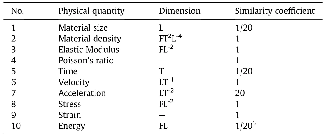
Table 1 Similarity ratio relationship of main physical quantities in scale model test.
2.1.Test layout and working conditions
To better study the effect of the underwater explosion on the target dam and adjacent dams,the four dam sections are set as a dam section group,and the dam body is shown in Fig.2.The height of the test dam is 2.50 m,the height of the dam head is 0.42 m,the width of the dam head is 0.42 m,the span of each dam section is 0.63 m,the total span of the 4 dam sections is 2.52 m,and the bottom width of the dam foundation is 2.57 m.
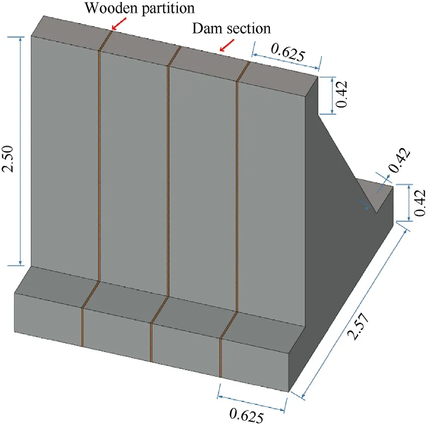
Fig.2.Layout of dam sections in scale test (Unit: m).
Considering the test requirements and construction methods comprehensively,a construction method of“segmented formwork and integral pouring”was adopted for the test dam section.The dam sections are divided by pine wood planks with good water absorption,which can meet the test requirements of the dam body joints.In addition,after the front of the dam is filled with water,the pine wood absorbs water and expands,which plays a good waterproofing role at the position of the dam section and prevents the water from overflowing from the back of the dam.
The water-retaining function of the dam on the river is simulated by excavating the channel,and the channel layout is shown in Fig.3.Dam section group A and dam section group B are located face to face on the bottom foundation of the same height,and the distance between them is 4 m.There is a foundation support constraint behind each dam section group to prevent the dam section group from causing excessive backwards displacement.The explosive is fixed with a steel frame and suspended in the water.After the steel frame is erected into the water,the parts of the steel frame on both sides of the waterway are fixed with heavy objects.
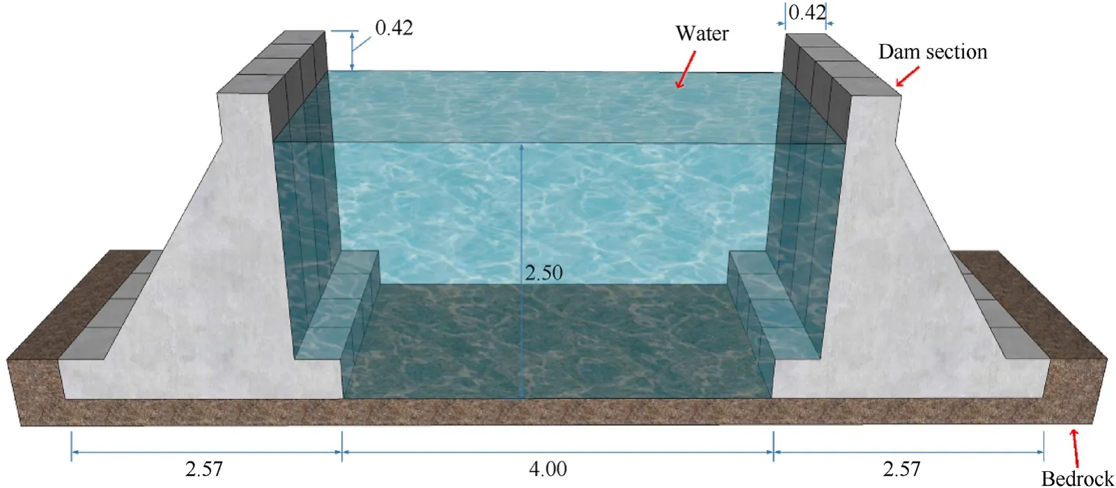
Fig.3.General arrangement of water channel and dam body (Unit: m).
Two rounds of tests were carried out.The TNT charges were 45 g and 400 g,respectively.The pressure sensor was arranged in the water,and the acceleration sensor was arranged on the downstream surface of the dam body.Table 2 gives the specific settings of the two working conditions.WhereWis the mass of the TNT charge,Dis the explosion depth of the explosive,Lis the distance between the explosive and the dam body,His the height of the water level in front of the dam,andR1andR2are the distance measurements of pressure sensorsP1andP2respectively.
2.2.Model materials and size
(1) Concrete
In the test,concrete was poured with on-site formwork,and a total of 8 dam bodies were poured into 2 dam section groups.The concrete mix ratio is shown in Table 3.The concrete water-binder ratio was 0.4.The 100×100×100 mm3concrete block was tested for compressive strength.The 7-day-old concrete compressive strength was 29.9 MPa,and the 28-day-old concrete compressive strength was 40.5 MPa,which meets the design requirements and related standards.

Table 3 Mix ratio of concrete.
(2) TNT
In the test,TNT was used as the starting explosive.TNT has good stability and is not sensitive to external disturbances such as friction and vibration.Fig.4(a)shows a 45 g TNT cylindrical pellet with a height of approximately 4.5 cm and a diameter of approximately 3.2 cm;Fig.4(b) shows a 400 g TNT pellet,which is composed of two 200 g standard TNT pellets.The block is approximately 10 cm long,approximately 6 cm wide and approximately 3 cm high.In the test,two medicine blocks are bound with insulating tape.A detonator was used for detonation in the test.
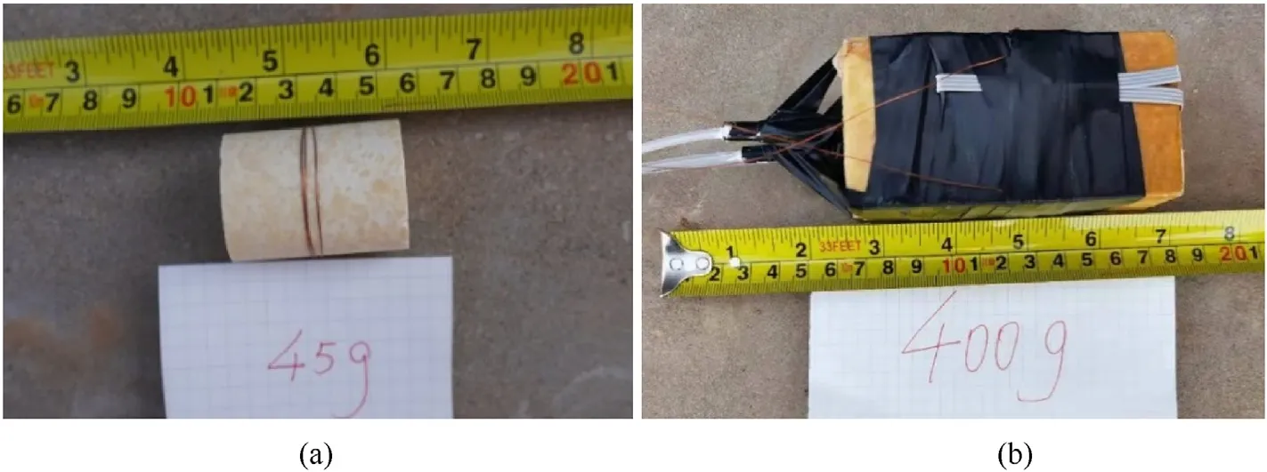
Fig.4.TNT charge: (a) 45 g TNT;(b) 400 g TNT.
2.3.Measuring equipment design and installation
2.3.1.Water pressure sensor arrangement
The water pressure sensor used in the test is shown in Fig.5.Combined with the test conditions,a water pressure sensor with a range of 100 MPa was selected for the test.To prevent the position of the pressure sensor in the water from changing,a steel pipe is used to suspend the sensor in the designated position,as shown in Fig.6 and Fig.7.

Fig.5.Water pressure sensor.
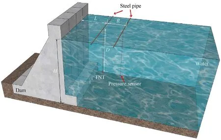
Fig.6.Schematic diagram of suspended pressure sensor in water.
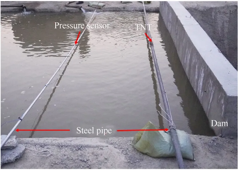
Fig.7.Place pressure sensor in field water.
2.3.2.Acceleration sensor arrangement on the dam
Several acceleration sensors were arranged on the gravity dam to measure the overall response of the dam body,and then the dynamic response law of the dam body was studied.The explosions in the test were all near-field/contact explosions,and the explosion-facing surface of the dam body was subjected to a considerable impact.To protect the sensors,the sensors of the dam body were mainly arranged on the downstream surface of the dam body.Since the acceleration sensor was arranged on the wading structure,attention should be given to waterproofing during the arrangement.
There were two dam sections in the test,and a total of 16 acceleration sensors were needed.Acceleration sensors were arranged in the middle two dam sections of each dam section group,and the layout positions were the dam head and the downstream dam surface,the middle and the lower part.The sensors were affixed with wires,waterproofed and attached to the dam body model according to the sensor layout plan.The accelerometer installation is shown in Fig.8.
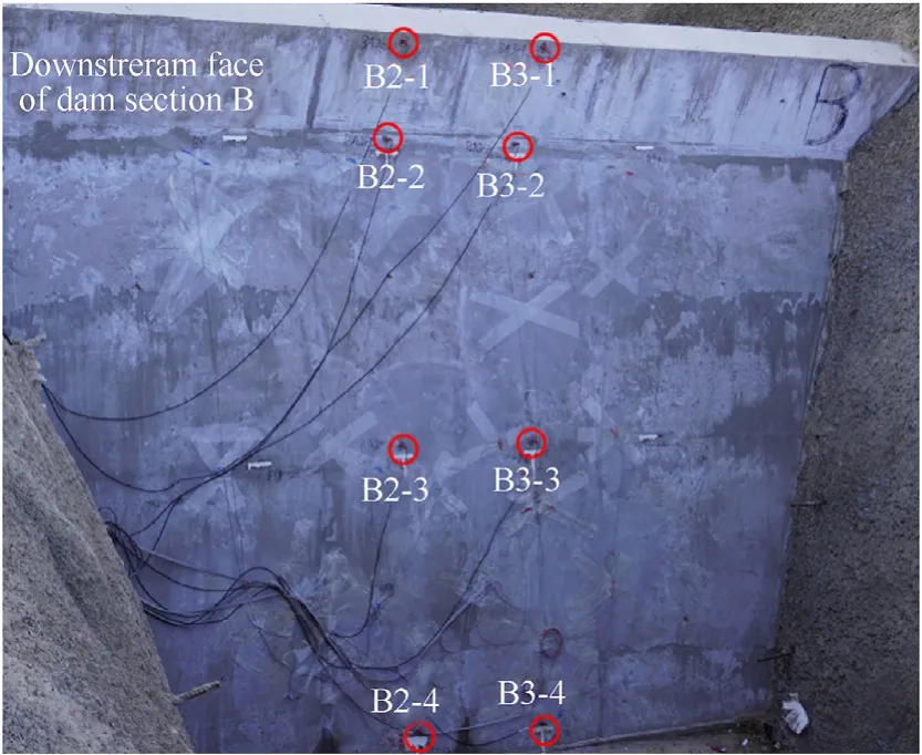
Fig.8.Acceleration sensor arrangement behind the dam.
2.3.3.Sensor selection and installation
The accelerometer selects two types of ranges.The middle and upper parts of the dam body are close to the explosion source,and the vibration is large.The range of the acceleration sensor is 10000g.The bottom of the dam body is far from the explosion source,the vibration is small,and the range of the acceleration sensor is 5000g.A unidirectional acceleration sensor is used as shown in Fig.9.
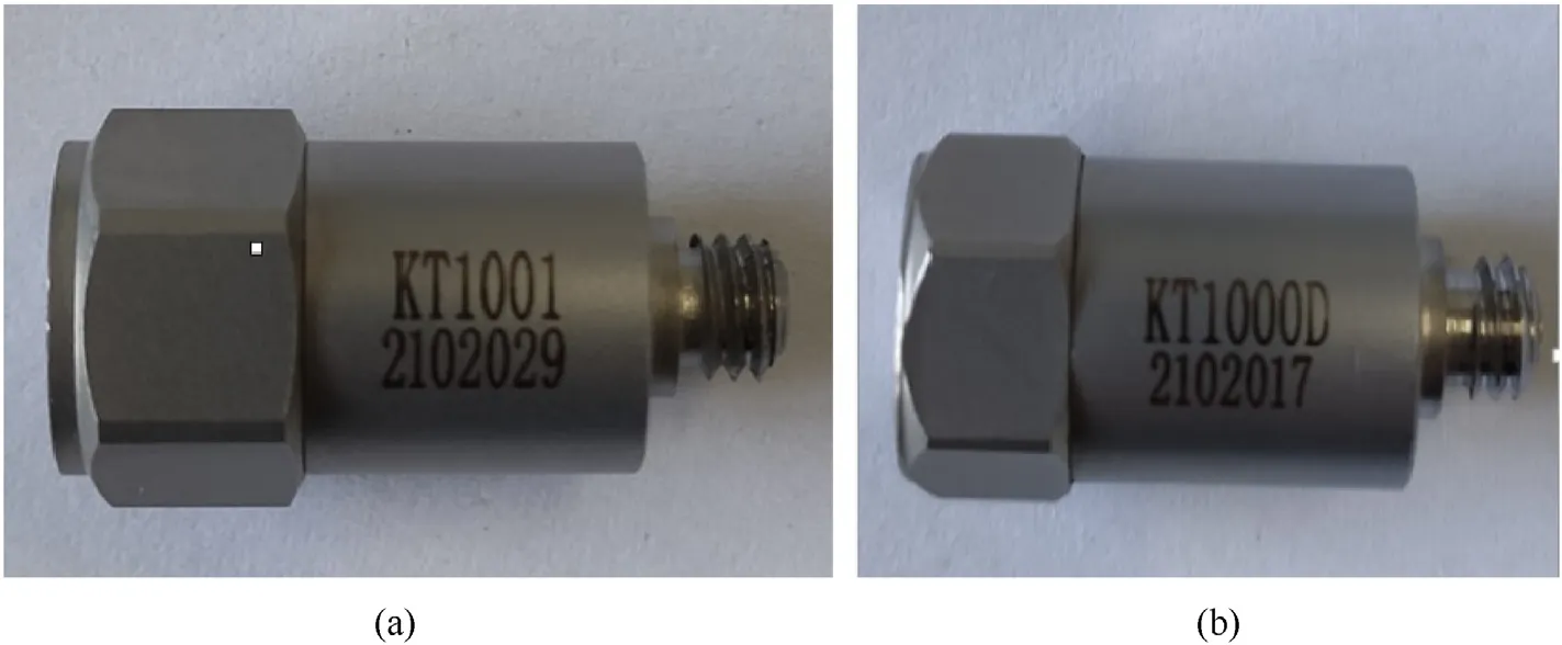
Fig.9.Acceleration sensor selection: (a) 5000g range unidirectional accelerometer;(b) 10000g range unidirectional accelerometer.
3.Test analysis
3.1.Analysis of pressure in water
3.1.1.Analysis of pressure propagation in water
When the explosive explodes underwater,the shock wave pressure time-history curve at a certain point instantly climbs to the pressure peak.According to Cole's empirical formula,the shock wave peak pressurePmat a certain point can be obtained as shown in Eq.(1).WhereRis the distance measurement,R0is the equivalent charge radius,andWis the charge quality.
Fig.10 shows the pressure time history curve of theP1measuring point in the A-1 working condition.The peak pressure of the shock wave is 8.27 MPa,which is 19.79% lower than the 10.31 MPa calculated by Cole's empirical formula.Fig.11 shows the pressure time history curve of theP2measuring point in the A-1 working condition.The peak pressure of the shock wave is 12.79 MPa,which is 21.53% lower than the 16.30 MPa calculated by Cole's empirical formula.Fig.12 shows the shock wave time-history curve measured by the underwater explosion with 400 g TNT,and the peak value of the shock wave pressure reaches 30.98 MPa,which is 16.52% lower than the 37.11 MPa calculated by Cole's empirical formula.
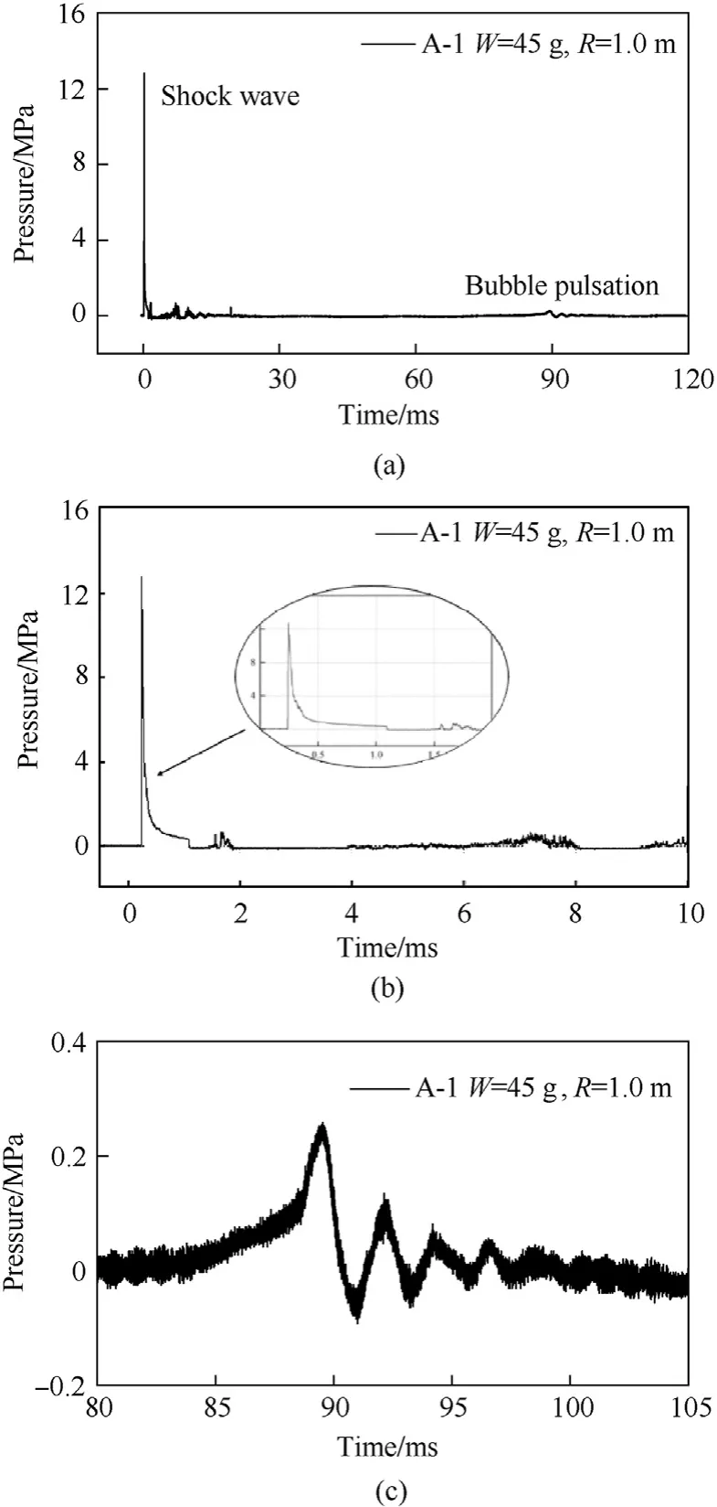
Fig.10.The measured curve of underwater explosion pressure at P1 under A-1 working condition: (a) Full-time curve of underwater explosion pressure at P1(W=45 g, R=1.0 m) under A-1 working condition;(b) Shock wave of underwater explosion;(c) Bubble pulsation of underwater explosion.
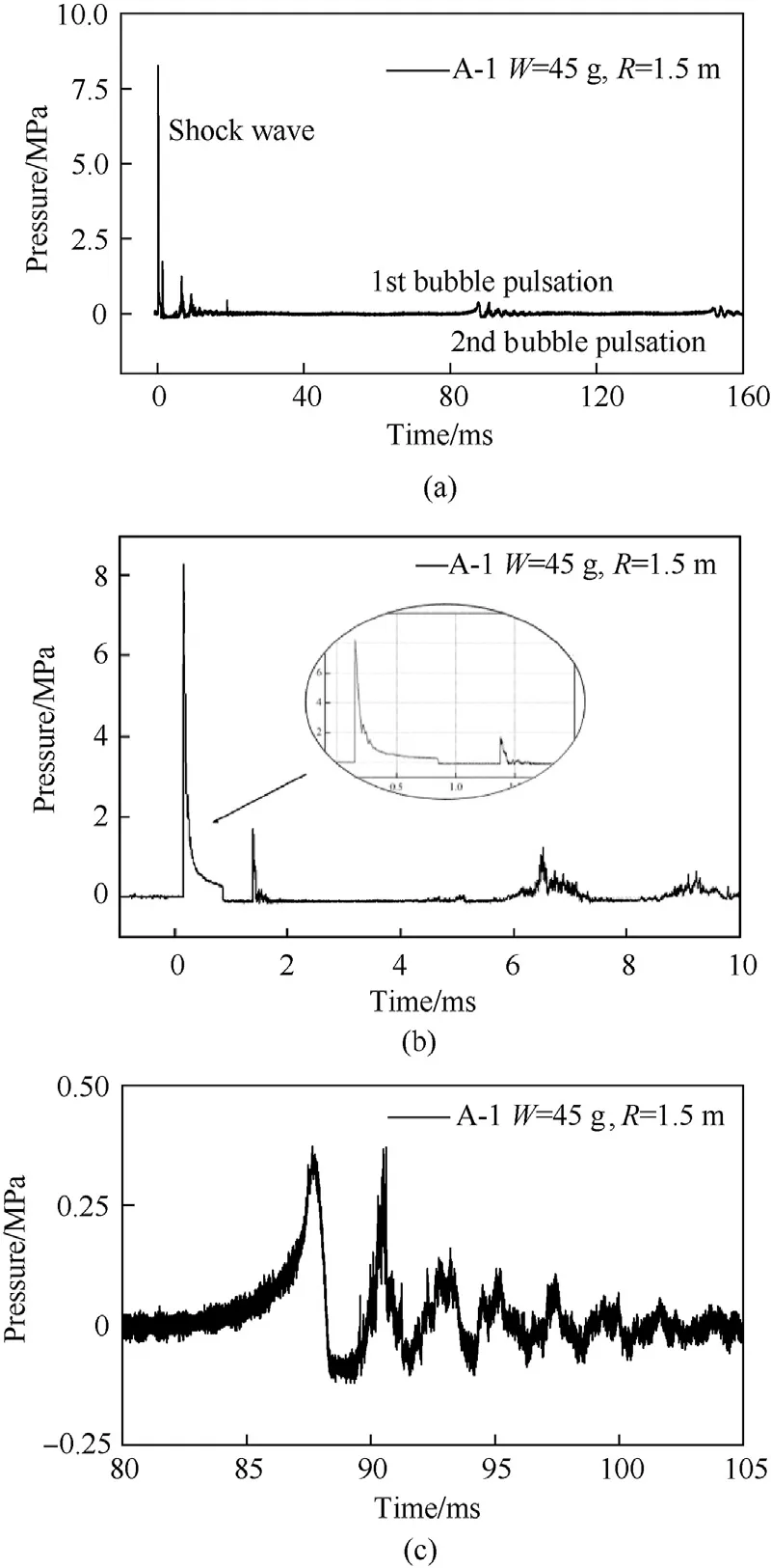
Fig.11.The measured curve of underwater explosion pressure at P2 under A-1 working condition: Full-time curve of underwater explosion pressure at P2 (W=45 g,R=1.5 m)under A-1 working condition;(b) Shock wave of underwater explosion;(c)Bubble pulsation of underwater explosion.
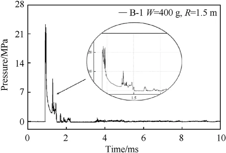
Fig.12.B-1 working condition (W=400 g, R=1.0 m) measured curve of water pressure in underwater explosion.
Cole gives the bubble pulsationTbtime in the underwater explosion of TNT,as shown in Eq.(2),whereHis the depth of the explosive into the water.
The underwater explosion test of the A dam section group measured the obvious bubble pulsation pressure,as shown in Figs.10 and 11,and even in the A-1 working conditionP2,a relatively obvious second bubble pulsation pressure was measured.The time of bubble pulsation pressure reaching the measuring point is later than that of the underwater explosion shock wave,and the peak pressure of bubble pulsation is much smaller than the peak pressure of the shock wave.The bubble pulsation time atP1is 89.37 ms,which is 8.2% lower than the empirical formula calculation result of 97.34 ms.It can be seen that the TNT charge detonates normally in water,and the shock wave propagation and bubble pulsation conform to the existing cognition law of underwater explosion.
3.2.Acceleration data processing
3.2.1.Acceleration fourier spectrum analysis
In the test,the acceleration signal was collected every 0.5 μs,and the collection time lasted until 0.18 s after the detonation.Each measurement point generates approximately 360,000 data points each time,which produces a very large amount of data.To obtain the correct acceleration time history from the raw data,the cut-off frequency of the low-pass filtering must be determined.Fast Fourier transformation (FFT) can observe the distribution of amplitude and energy in the frequency domain,so the main frequency distribution range can be analysed through Fourier transformation and the basic processing of the original data.
Fig.13 shows a schematic diagram of the number of acceleration sensors on the downstream surface under the A/B-1 working condition.In the A-1 working condition,the No.3 dam section is the target dam section,and the No.2 dam body is the adjacent dam section.In the B-1 working condition,the target dam section is the No.2 dam section,and the No.3 dam section is the adjacent dam section.The acceleration signals of A3-1,A3-3,B2-1 and B2-3 are selected for spectrum analysis,as shown in Figs.14-17.The main frequency of the acceleration signal measured at the target dam section is roughly in the bandwidth range of 0 Hz-20000 Hz,and the signal energy is basically distributed in this frequency range.According to the Nyquist sampling law,the sampling frequency is 2.56-4 times the signal bandwidth to ensure that the complete signal information is preserved.To ensure that the sampling bandwidth of the main waveform of the acceleration signal meets the requirements,100000 Hz is set as the sampling frequency.Therefore,the time interval for collecting data is 10 μs.
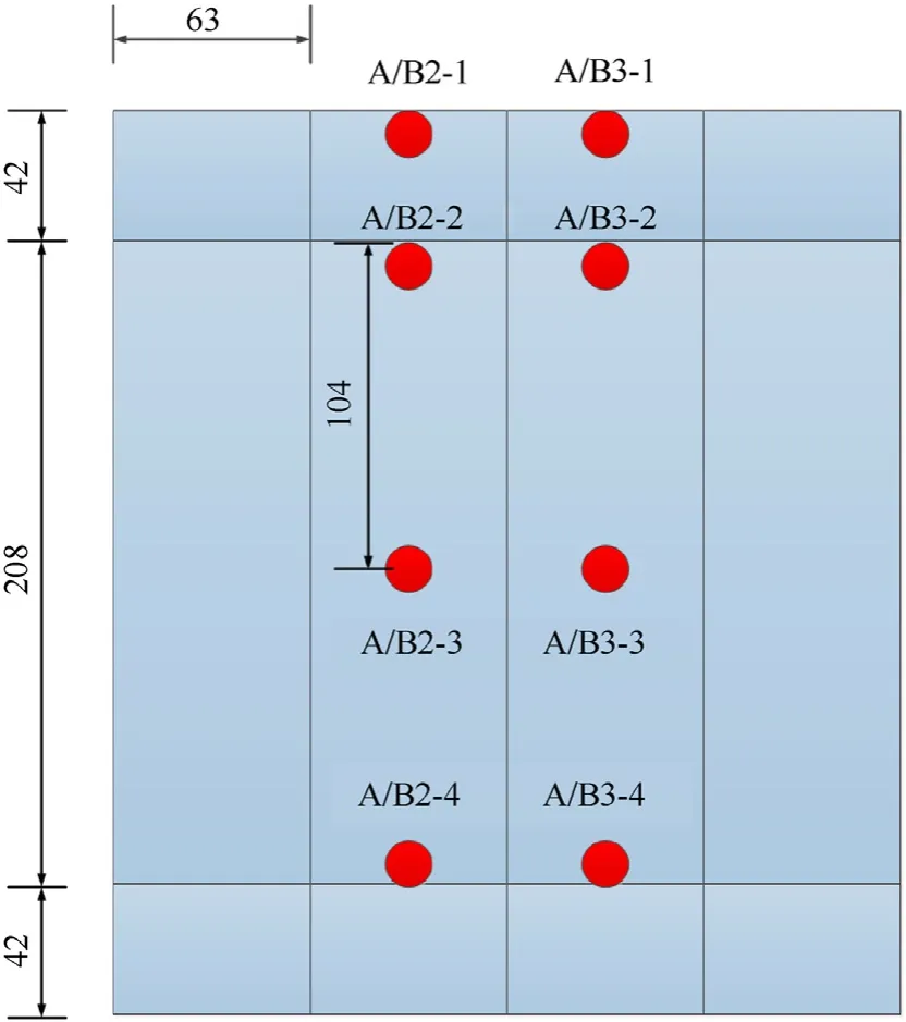
Fig.13.Schematic diagram of the acceleration sensor number on the downstream surface of the dam body (unit: mm).
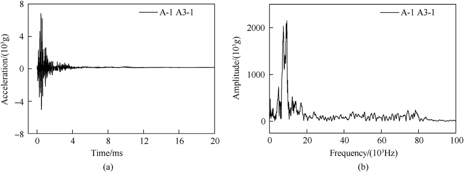
Fig.14.The acceleration signal and Fourier spectrum of the A3-1 point in the A-1 working condition: (a) Raw data of A3-1 acceleration in A-1 working condition;(b) A3-1 acceleration Fourier spectrum in A-1 working condition.
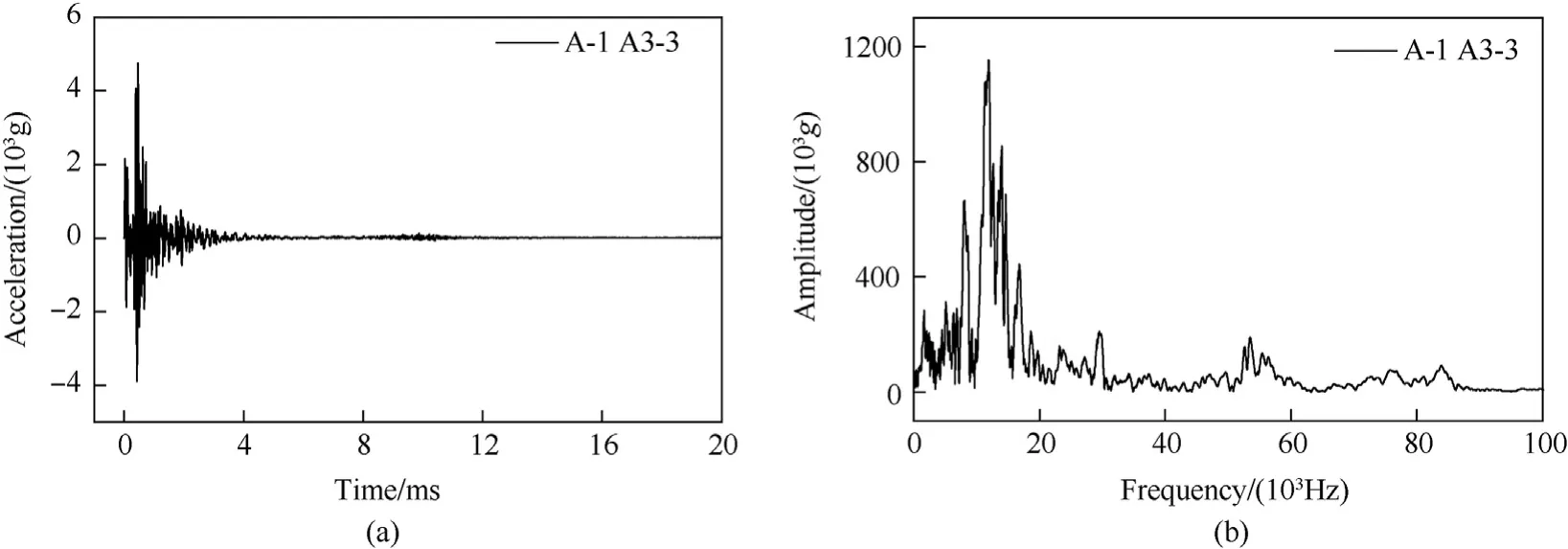
Fig.15.The acceleration signal and Fourier spectrum of the A3-3 point in the A-1 working condition: (a) Raw data of A3-3 acceleration in A-1 working condition;(b) A3-3 acceleration Fourier spectrum in A-1 working condition.
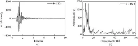
Fig.16.The acceleration signal and Fourier spectrum of the B2-1 point in the B-1 working condition: (a) Raw data of B2-1 acceleration in B-1 working condition;(b) B2-1 acceleration Fourier spectrum in B-1 working condition.
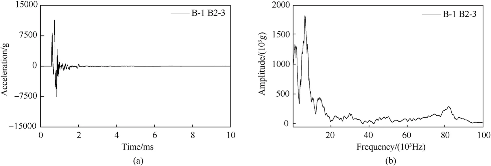
Fig.17.The acceleration signal and Fourier spectrum of the B2-3 point in the B-1 working condition: (a) Raw data of B2-3 acceleration in B-1 working condition;(b) B2-3 acceleration Fourier spectrum in B-1 working condition.
3.2.2.Acceleration zero drift processing
Take the acceleration signal of A-1 working condition A3-4 as an example.Fig.18 shows the A3-4 raw acceleration signal data.There is a zero drift phenomenon in the original acceleration signal,and the acceleration curve of the structure deviates from the zero line after the shock wave,which is inconsistent with the actual situation.
Select an appropriate polynomial function to perform least squares fitting on the raw acceleration signala(n).The fitting obtains a polynomial sequence that can be regarded as a lowfrequency trend term,as shown in Eq.(3)
wheremis the polynomial order.Subtracting the polynomial sequence from the original signala(n)removes the trend term in the acceleration signal.Fig.19 shows a comparison between the processed acceleration signal and the original signal,and Fig.20 shows a comparison between the A3-4 original acceleration signal and the trend item.The acceleration signal measured in the test can be effectively corrected by removing the trend item.The processed acceleration is integrated to obtain the velocity time-history curve and the displacement time-history curve of the point,as shown in Fig.21.After the shock wave reaches the dam body,the dam body responds strongly,the acceleration oscillates violently,the velocity rises rapidly and then attenuates rapidly after reaching the peak value,the displacement also rises rapidly and then rebounds,and the rebound amplitude is even larger than the rise amplitude.After that,the acceleration quickly decays to zero,the velocity also decays to zero,and the displacement stabilizes at a fixed value after oscillation.The time history and displacement curve after the shock wave finally fluctuate around the zero value,which is consistent with the actual situation,proving that the zerodrift processing method of the acceleration signal adopted in this paper is feasible.
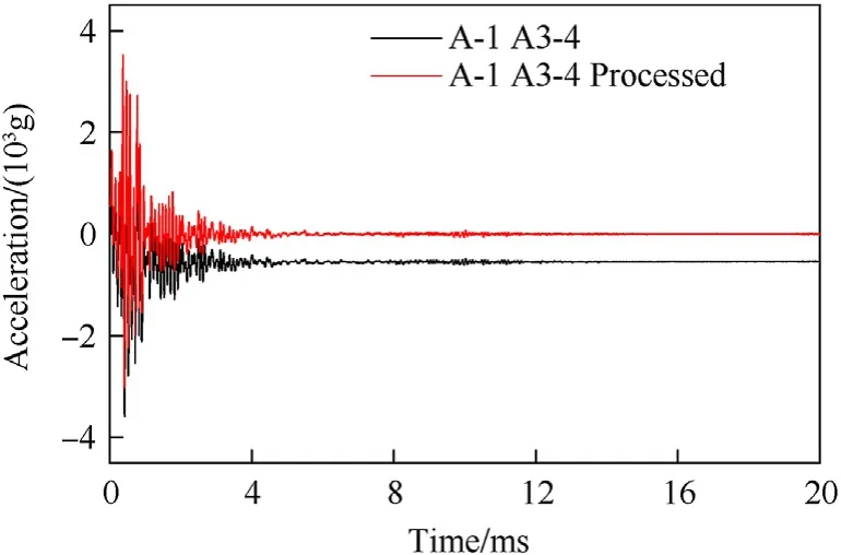
Fig.19.A3-4 acceleration signal zero drift processing in A-1 working condition.
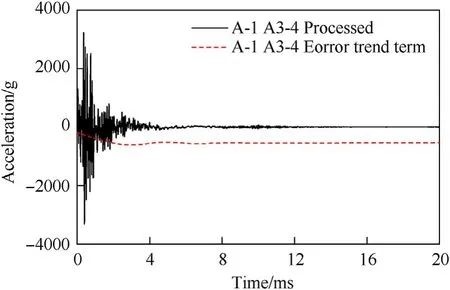
Fig.20.A3-4 acceleration signal removal trend item in A-1 working condition.
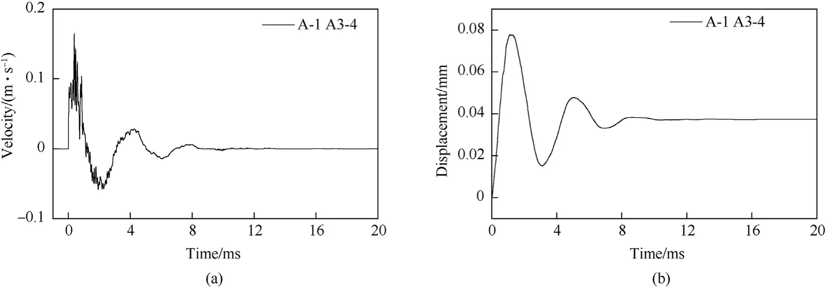
Fig.21.A3-4 velocity and displacement time history curves in A-1 condition: (a) velocity curve at A3-4;(b) Displacement curve at A3-4.
3.3.Analysis of test results
3.3.1.Acceleration response of dam section A
The water level in front of the dam simulates a full reservoir(2.5 m).After the underwater explosion of a small dose of TNT,a water mound was formed on the water surface,but there was no excessive splashing,and the dam body maintained good integrity without obvious damage.
Fig.22 and Fig.23 show the acceleration responses of dam section 2 and section 3 in the A-1 working condition,where the No.3 dam axis is facing the explosion source as the target dam section,and the No.2 dam section is the adjacent dam section.In the A-1 test,there was an obvious bubble pulsation phenomenon.When bubble pulsation is applied to the dam body,the dam body has a certain vibration response,but the peak acceleration response of the dam body under the action of bubble pulsation is only 1/100 of the peak acceleration of the dam body under the action of a shock wave.Under this working condition(proportional blast distanceR/W1/3=4.21 m/kg1/3),the dynamic response of the concrete gravity dam is mainly caused by the shock wave,and the dynamic effect of the bubble pulsation on the concrete gravity dam is almost negligible.
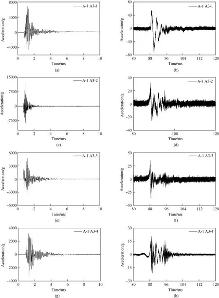
Fig.22.The acceleration response of the target dam section(No.3)in the A-1 working condition:The acceleration of the dam body under the action of the shock wave at A3-1;(b)Acceleration of the dam body due to the pulsation of air bubbles at A3-1;(c)Acceleration of the dam body under the action of shock wave at A3-2;(d)Acceleration of the dam body under the action of bubble pulsation at A3-2;(e)Acceleration of the dam body under the action of shock wave at A3-3;(f)Acceleration of the dam body under the action of bubble pulsation at A3-3;(g) Acceleration of the dam body under the action of shock wave at A3-4;(h) Acceleration of the dam body under the action of bubble pulsation at A3-4.

Fig.23.Acceleration response of adjacent dam section(No.2)in working condition A-1:(a)Acceleration of the dam body under the action of shock wave at A2-1;(b)Acceleration of the dam body under the action of bubble pulsation at A2-1;(c)Acceleration of the dam body under the action of shock wave at A2-2;(d)Acceleration of the dam body under the action of bubble pulsation at A2-2;(e)Acceleration of the dam body under the action of shock wave at A2-3;(f)Acceleration of the dam body under the action of bubble pulsation at A2-3;(g) Acceleration of the dam body under the action of shock wave at A2-4;(h) Acceleration of the dam body under the action of bubble pulsation at A2-4.
Table 4 shows the peak acceleration of each point of the dam under the A-1 working condition,and the acceleration response at the dam neck(A3-2)is the largest.The thickness of the dam neck is not only the thinnest of the dam body but also the location of the horizontal plane,which leads to a sharp increase in the acceleration at the dam neck.The acceleration of the dam body near the dam foundation decreases,and it can be seen that the effect of underwater explosion on the dam body is mainly concentrated in the middle and upper parts.The bottom of the dam is constrained by the dam foundation and is far from the explosives in the water,so the dynamic response here is small,which also proves that the damage of the dam body is not serious under this condition.

Table 4 Acceleration response peak of No.3 and No.2 dam sections in A-1 working condition.
3.3.2.The macroscopic phenomenon of dam section B
A large charge underwater explosion test was carried out in dam section B,and the test situation is shown in Fig.24.When the 400 g TNT standard charge explodes at a depth of 1.5 m,the water surface will react violently,with a high water mound and water jet height.Although the explosion depth of the explosives in this working condition is deepened,the splash height of the water splash increases,and the reservoir water in front of the dam directly overflows the dam head.
After the test explosion,it was found that the explosion caused cracks in the head of the dam,there were many cracks in the middle back of the dam body,and the reservoir water overflowed from the cracks seriously,as shown in Fig.25.After the explosion,the dam body was seriously damaged,it was difficult to maintain the basic function of retaining water,and the dam body was completely damaged.
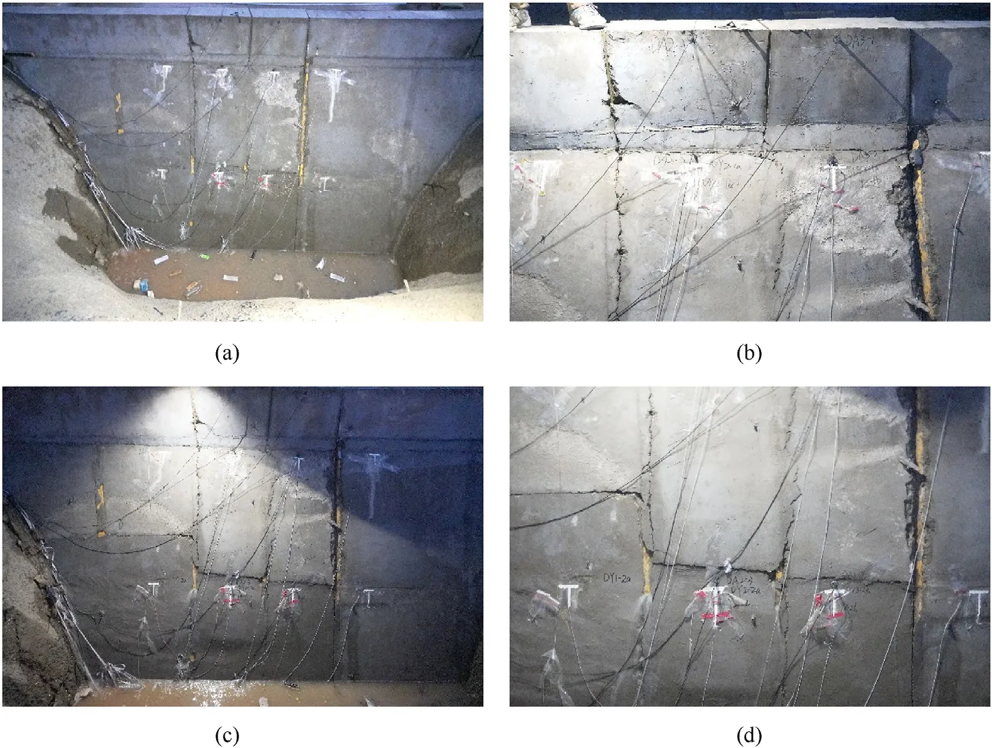
Fig.25.The damage of the test dam body in the Dam Section B: (a) Leakage behind Dam Section B after the test;(b) Dam head damaged after the test;(c) Cracks behind Dam Section B after the test;(d) Local cracks behind Dam Section B after the test.
After the test,the reservoir water was pumped out.Fig.26 shows the damage on the upstream face of dam section B.There are two obvious cracks at the dam neck on the upstream face of the target dam body,at 56 cm and 73 cm away from the dam crest.There is an obvious crack at the dam head of the adjacent dam section,approximately 66 cm from the dam crest.There are obvious fractures at the connection between the dam body and the dam foundation,and all the dam foundations of the adjacent dam sections are also cracked.When the 400 g TNT charge explodes at a depth of 1.5 m underwater,the dam body is destroyed as a whole,the dam foundation is directly damaged,and the dam body produces through-cracks.
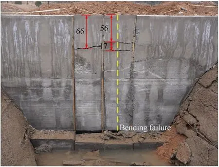
Fig.26.Damage to the upstream face of Dam Section B (Unit: cm).
Fig.27 shows the damage on the downstream surface of the dam section B group after the test,and there are cracks at the dam head of the target dam section facing the explosion source.There is a horizontal crack in the dam body 115 cm below the dam neck.The dam head is slightly displaced backwards.There is a slight horizontal crack at the dam neck of adjacent dam section No.3,and there is a horizontal crack at the dam body 118 cm below the dam neck.The rear of dam No.3 is approximately 2 cm higher than that of dam No.2.This is because the explosive exploded near the lower part of the dam body,the lower part of the dam body was directly affected by the shock wave,and the dam body bulged backwards.
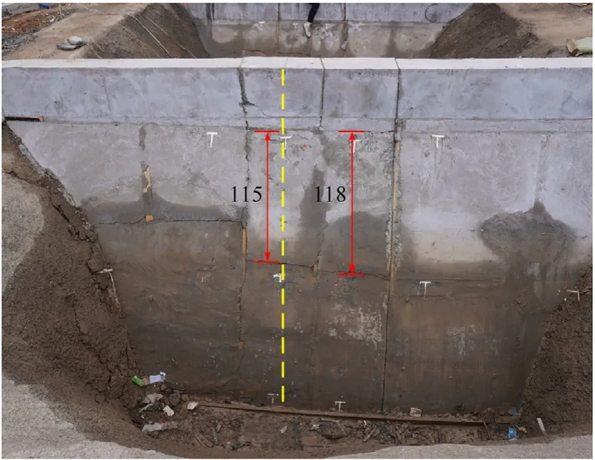
Fig.27.Damage on the downstream face of Dam Section B (Unit: cm).
3.3.3.Acceleration response of dam section B
Fig.28 and Fig.29 show the acceleration response of the dam section in the B-1 working condition,and Table 5 shows the peak acceleration of each point on the dam body.Due to the sensor range problem,the acceleration signal at point B2-4 is truncated,and the actual acceleration peak value here is larger than 5268.81g/-5923.90g.After the shock wave between the target dam section and the dam neck of the adjacent dam section,a secondary acceleration peak appears,approximately 16 ms from the first acceleration peak,and the secondary acceleration peak is approximately 1/10 of the first acceleration peak.Due to the stress concentration at the dam neck and the influence of the horizontal plane,the resistance is weak,and obvious damage at the dam neck can be seen in Fig.27(b).The interaction between the dam bodies leads to the appearance of secondary acceleration peaks.

Table 5 Peak acceleration response of No.2 and No.3 dam sections in B-1 working condition.

Fig.29.Acceleration response of No.3 dam section in B-1 condition: (a) B3-1;(b) The first acceleration peak at B3-2;(c) Second acceleration peak at B3-2;(d) B3-3;(e) B3-4.
It can be seen in Table 5 that the overall dynamic response of the dam body of the target dam section(No.2)is larger than that of the adjacent dam sections,especially in the middle of the dam body.The peak acceleration of the No.2 dam section (11384.99g/-7561.28g) is 2-3 times that of the No.3 dam section (3719.15 g/-4501.83g).The dam body joints can better protect the adjacent dam sections.
Comparing the peak accelerations of the dam body in the A-1 working conditions and the B-1 working conditions in Tables 4 and 5.It can be seen that in the A-1 working condition,except for the maximum peak acceleration peak value at the dam neck of the target dam section,the acceleration peak values of other parts of the target dam body and the adjacent dam body are generally larger.It can be seen that in the A-1 working condition,the target dam section and the adjacent dam section jointly bear the explosion effect.Because the blasting distance is far from the dam body,when the shock wave reaches the dam body,it interacts with the dam body in a large area,so both the target dam body and the adjacent dam body show large acceleration peaks.In the B-1 working condition,the explosives are relatively close to the dam body,and the area of the dam body under the shock wave is concentrated.In addition,the target dam body-adjacent dam body is divided into joints,and the acceleration peak value of the target dam body is significantly larger than that of the adjacent dam sections.
4.Numerical simulation analysis of gravity dam damage
4.1.Numerical model
Numerical simulations of the test dam are carried out to establish the corresponding numerical model (see Fig.29).The damage evolution process of gravity dams is analysed.Combined with the actual test situation,to improve the calculation efficiency,this section adopts 1/2 symmetry modelling.To more accurately simulate the dynamic response of the target dam body under the action of underwater explosion,the indirect constraint method is used to provide constraints on the target dam section,that is,the base rock is established to provide the bottom and rear supports for the target dam section.Adjacent dam sections are established to provide support for the target dam section in the direction of the dam axis.Fig.30 shows the geometric numerical model of the underwater explosion of a concrete gravity dam.The foundation is arranged under the dam body and the water area.To reduce the influence of the boundary on the calculation results,the thickness of the foundation is similar to the thickness of the dam foundation(0.42 m),which is taken as 0.5 m,and the foundation redundancy after the dam is also taken as 0.5 m.Taking the target dam section(central dam section) as the research target,fixed constraints are imposed on the bottom and rear of the foundation,and constraints in the direction of the dam axis are imposed on the back of the target dam section.Constraints are imposed on the target dam section through the adjacent dam sections and the foundation so that the dynamic response of the target dam section conforms to the actual engineering situation.

Fig.30.Numerical model of underwater explosion.
The meshing of the model adopts hexahedral solid elements,and the underwater explosion is very sensitive to the size of the element mesh,but the fine meshing of all waters will increase the workload.The explosive is detonated in the water close to the dam body,so the mesh is densified within 1 m near the explosion centre,and the mesh size is 6 mm to ensure the quality of the mesh near the explosion source.The calculation cost can be saved on the premise of ensuring the impact load accuracy of the dam body.The grid of the dam body and the bedrock matches the grid in the water,which is also 12 mm.
A nonreflective boundary is imposed around the water medium,mitigating the influence of the environment on the simulation results.The dam-dam section and the dam-bedrock adopt surface-tosurface contact,and the contact surface is specified to transmit pressure and separate when under tension.The fluid-structure coupling algorithm is used to address the interaction between the load and the structure in the water.The water body adopts the Euler element,and the water-explosive adopts the multisubstance algorithm to describe the material flow.The dam body-bedrock adopts Lagrangian elements to describe the large deformation of the structure.Atmospheric pressure is applied to the water surface in a uniform pressure manner,and a downwards acceleration is applied in the model to simulate the actual gravitational acceleration.
The energy release process of the explosive is described by the
*HIGH_EXPLOSIVE_BURN material model,and the pressure of the detonation product is described by the JWL equation of state given in Eq.(4).
wherePis the pressure of the detonation product;Vis the relative volume of the detonation product;and A,B,R1,R2and ω are the parameters of the state equation.Table 6 gives the parameter values of the TNT explosive material.

Table 6 Parameters of equation of state for underwater explosive charge.
The *EOS_GRUNEISEN equation is used to describe the state of the water medium.When the water medium is in a pressurized state,the state equation is shown in Eq.(5)
where ρ0is the initial density of the water medium,which is 1000 kg/m3,andC0is the speed of sound in the water medium;the other parameters are shown in Table 7.

Table 7 Gruneisen equation of state parameters for water.
In the test,the bottom of the channel is supported by shotcrete to simulate the action of bedrock,and concrete material models are used to describe the dynamic response of the gravity dam and bedrock.The concrete RHT constitutive model can better simulate the dynamic response of concrete materials,and the measured strength of the dam concrete in the test is 40.5 MPa.Combined with the actual situation of the test,the material parameters of the concrete and steel plate are given in Table 8.

Table 8 Material parameters of concrete.
The numerical models corresponding to working conditions A-1 and B-1 are established,and the specific arrangement is shown in Table 9.

Table 9 The geometric parameters of the numerical model corresponding to the test conditions.
4.2.Numerical calculation result verification
4.2.1.Pressure propagation verification in water
A concrete gravity dam produces a strong dynamic response under the action of an underwater explosion shock wave.The accuracy of numerical simulation of underwater explosion shock waves is the premise of correctly simulating the dynamic response of the structure.Fig.31 shows the numerical simulation of the shock wave attenuation process generated by the underwater explosion of different charges.It can be seen that the numerical model can accurately obtain the peak pressure of the shock wave of the underwater explosion,and the shock wave attenuation has a high degree of conformity with the test results.The underwater explosion shock wave load in the numerical model has high reliability.
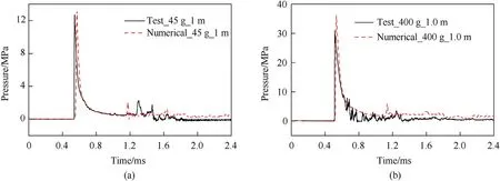
Fig.31.Comparison between numerical calculation results of pressure shock waves in water and experiments: (a) W=45 g, R=1.0 m;(b) W=400 g, R=1.0 m.
4.2.2.Dam acceleration verification
To reduce the influence of boundary conditions on the calculation results,the response of the target dam section is mainly discussed in the analysis.The acceleration time-history curve of the corresponding point on the model is selected and compared with the experimental data.Fig.32 shows the comparison between the numerical calculation results of the acceleration time-history curves at A3-2 and A3-3 of the target dam section in the A-1 working condition and the test results.The peak value of the acceleration of the dam body is close,and the trends of convergence and attenuation are relatively consistent.After the shock wave acts on the dam body,the acceleration of the dam body rapidly rises to the peak value and then attenuates and converges to the baseline.

Fig.32.Comparison between the numerical simulation results and the experimental results of the acceleration of the dam body in the A-1 working condition: (a) A3-2 in A-1 working condition;(b) A3-3 in A-1 working condition.
Similarly,taking the B-1 working condition as an example to establish a numerical model,the comparison between the numerical simulation results and the test results of the acceleration response of the target dam body is shown in Fig.33.Because the dam head is at the highest point and is far from the horizontal plane,the acceleration signal there is accidental.In general,the acceleration response of the dam body obtained by the numerical simulation is in good agreement with the experimental results.The errors of numerical calculation mainly include the following aspects.First,the initiation and energy release of underwater explosions are very complex chemical and physical processes,and the resulting structural accelerations are highly random due to the interference of various factors.Second,the concrete material has strong discreteness and obvious force nonlinear characteristics,and there are differences between the experimental data and the numerical simulation results.Third,the boundary conditions of the test are complex,the influence of the surrounding environment cannot be ignored,and it is difficult for the numerical model to accurately simulate the actual situation of the restoration test.
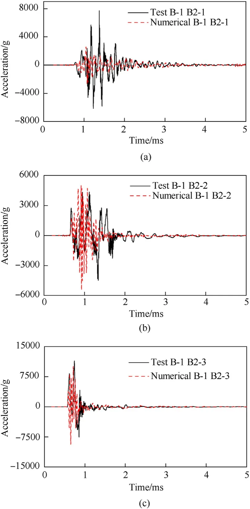
Fig.33.Comparison between the numerical simulation results and the experimental results of the acceleration of the dam body in the B-1 working condition:(a)B2-1 in B-1working condition;(b) B2-2 in B-1working condition;(c) B2-3 in B-1working condition B-1.
4.3.Macroscopic damage evolution of the dam body
In test condition B-1,the damage of the dam body is obvious,and the damage of the target dam section is mainly concentrated in the dam neck,the middle part of the dam body and the dam foundation.There are cracks at the neck of the dam,damage to the middle of the dam body,and serious damage to the dam foundation.Fig.34 shows the damage results of the dam under the B-1 working condition.Due to the large amount of charge,the concrete damage of the dam in the numerical simulation is very serious,mainly concentrated on the upstream surface facing the explosion source.In addition,there are serious penetration cracks in the dam neck,the dam head remains intact as a whole,the internal damage of the dam body is serious,an obvious damage zone is formed in the middle of the dam body,and local serious damage occurs at the corner of the dam foundation due to stress concentration.It can be seen that in terms of the macroscopic damage of the dam body,the numerical simulation reflects the damage of the dam body in the test more comprehensively.

Fig.34.Numerical simulation results of dam damage in working condition B-1.
Fig.35 shows the damage evolution process of the dam body in the numerical simulation B-1 condition.After the explosive is detonated,due to the large amount of charge,the blasting face of the dam body is damaged over a wide range,and stress concentration is formed at the dam foundation.Two milliseconds after detonation,a stress concentration was formed on the downstream surface of the dam neck,the damage at the dam foundation continued to develop,and the upstream damage concentrated on the target dam section and developed into the dam on the symmetrical plane.Four milliseconds after detonation,the damage zone at the dam neck runs through the dam body,and the damage at the dam foundation develops into the interior of the dam body.Eight milliseconds after the detonation,the dam foundation at the rear of the dam body was damaged,the dam body was seriously damaged,and the dam body was almost completely damaged.Comprehensive analysis of the damage evolution of the dam body shows that after the explosive is detonated,the upstream surface of the dam body is first impacted and then spreads to the top and bottom of the dam body to the dam neck slope break and the dam foundation,respectively.Due to the sudden change in the section at the dam neck slope break,it is very easily damaged.After the dam neck is damaged,the dam head will maintain a certain integrity and will not break into pieces.Similarly,there are also problems of cross-section sudden change and stress concentration at the dam foundation.Because the bottom of the dam body is restrained by the foundation,the rear part of the dam body and the dam foundation will be damaged by compression.
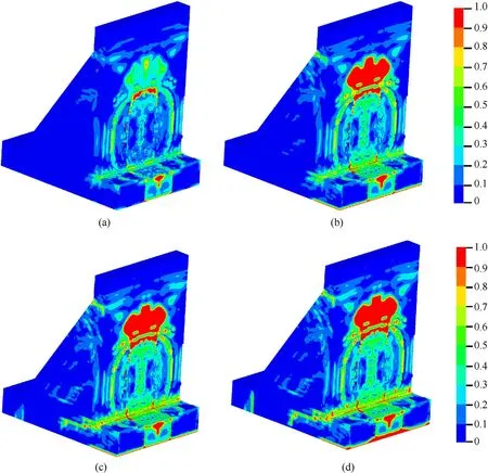
Fig.35.Damage evolution process of dam body after 400 g TNT exploded underwater:(a)Dam damage after 1.0 ms of detonation;(b)Dam damage after 2.0 ms of detonation;(c)Dam damage after 4.0 ms of detonation;(d) Dam damage after 8.0 ms of detonation.
After the underwater explosion shock wave acts on the dam body,the damage development law of the dam body is that the parts close to the explosion source are damaged first,and the parts far away from the explosion source are damaged later.Thin parts,such as the neck,are damaged first,and thick parts,such as the dam body,are damaged later.Stress concentration parts,such as dam necks and dam foundations,easily accumulate damage and cause damage.
The shock wave generated after the explosion in the water first causes overpressure damage to the target dam section facing the explosion source.Over time,the overall effect of the impulse on the dam body becomes more obvious.For the constant gravity model test,the peak pressure of the shock wave generated by the water explosion is similar to that of the prototype water explosion.However,the impulse is greatly affected by gravity in the water,so the damage effect of the impulse after the peak pressure of the shock wave on the dam body in the model test is not similar to that of the prototype dam body.
5.Conclusions
In this paper,an underwater explosion test of a 2.5-m-high concrete gravity dam is designed,and the problems of test organization,test data acquisition and test data processing are studied.Starting from the water pressure and the acceleration of the dam body,the pressure characteristics of the underwater explosion in front of the dam and the dynamic response of the dam body are discussed.Second,taking the dam damage test as an example,a numerical model of concrete gravity dam damage under underwater explosion is established,and the damage evolution of the dam body is analysed.
This paper draws the following conclusions:
(1) In the experiment,the water-retaining function of the dam on the river was simulated by excavating the channel.The A dam section group and B dam section group are located face-to-face on the bottom foundation of the same height,and each dam section group is backed by a foundation support constraint to prevent the dam section from causing excessive backwards displacement.In the test,the construction method of “segmented formwork and integral pouring”was adopted,and the dam sections were divided by pine wood planks with good water absorption to meet the test requirements of the dam body's joints and have a good waterproofing effect.
(2) Two underwater explosion tests with different charges,blast distances and blast depths are designed.Pressure sensors are installed in the water and on the wall of the dam to measure the pressure in the water.Acceleration sensors are arranged behind the dam of the target dam section and adjacent dam sections to measure the dynamic response of the dam body.The pressure sensor measured the shock wave pressure and bubble pulsation pressure of the underwater explosion,which proved that the explosive detonated normally in the test.
(3) A Fourier transform is performed on the acceleration data obtained in the test to determine the frequency range of the main distribution of the acceleration signal,and then the sampling frequency and sampling time interval of the acceleration signal are determined.In the experiment,some acceleration signals have a zero drift phenomenon,and the method of eliminating trend items is used to correct the zero drift phenomenon in the acceleration signals.
(4) Through the analysis of the results of the two test conditions,it is found that when the explosion distance is large,even if the underwater explosive charge is small and the damage to the dam body is not obvious,the peak acceleration of the target dam body and the adjacent dam body will reach more than 2000g.However,in a large-dose underwater explosion with a near-explosive distance,the shock wave acts on the dam body in a concentrated area.In addition,for the joint effect between the target dam body and the adjacent dam body,the acceleration peak value of the target dam body is significantly larger than that of the adjacent dam sections.The dam body joints can effectively protect the adjacent dam sections.
(5) The peak value of the acceleration transient response of the dam body under the action of a shock wave can reach several thousandg,and the acceleration response of the dam body under the action of bubble pulsation is only 1/100 of the acceleration response under the action of a shock wave.The dynamic response of the dam body under the action of underwater explosion is mainly caused by the shock wave.Under the action of a large-charge explosion,the acceleration at the dam neck of the dam body has a secondary peak within 20 ms after the shock wave,which may be caused by the internal action of the concrete after the damage at the dam neck.The appearance of the secondary peak of acceleration may be one of the signs of internal concrete failure.
(6) A finite element numerical model is established,and the reliability of the model is verified by comparing the numerical simulation results with the test results.Then,the damage evolution of the dam body is analysed.The study found that after the water explosion,the shock wave first acted on the dam body to cause local damage,and then the impulse acted on the dam body to cause overall damage.The damage development law of the dam body is that the part close to the explosion source is destroyed first,and the part far from the explosion source is destroyed later.Weak parts,such as the neck,are damaged first,and thicker parts,such as the dam body,are damaged later.Stress concentration parts,such as dam necks and dam foundations,are prone to cumulative damage.
Declaration of competing interest
The authors declare that they have no known competing financial interests or personal relationships that could have appeared to influence the work reported in this paper.
杂志排行
Defence Technology的其它文章
- An energetic nano-fiber composite based on polystyrene and 1,3,5-trinitro-1,3,5-triazinane fabricated via electrospinning technique
- Dynamic response of UHMWPE plates under combined shock and fragment loading
- Aerial multi-spectral AI-based detection system for unexploded ordnance
- Model-based deep learning for fiber bundle infrared image restoration
- Robust design and analysis for opto-mechanical two array laser warning system
- Combustion behavior and mechanism of molecular perovskite energetic material DAP-4-based composites with metal fuel Al
