Multi-stage penetration characteristics of thick ultra-high molecular weight polyethylene laminates
2023-10-09MingjinCoLiChenRongzhengXuSijiLiuQinFng
Ming-jin Co ,Li Chen ,* ,Rong-zheng Xu ,Si-ji Liu ,Qin Fng ,c
a Engineering Research Center of Safety and Protection of Explosion & Impact of Ministry of Education,Southeast University,Nanjing,211189,China
b Institute of Architectural Engineering,Huanghuai University,Zhumadian,463000,China
c State Key Laboratory of Disaster Prevention & Mitigation of Explosion & Impact,Army Engineering University of PLA,Nanjing,210007,China
Keywords:UHMWPE laminates Ballistic limit Thickness Mechanism Energy limit
ABSTRACT To further reveal the failure mechanisms of thick ultra-high molecular weight polyethylene (UHMWPE)laminates,field firing tests were conducted for 10-,20-,and 30-mm thick laminates against 12.7-mm calibre wedge-shaped fragment simulated projectiles at high velocities between 450 and 1200 m/s.The ballistic performance,deformation process,and staged failure characteristics of the laminates with different thicknesses were compared and analysed.The results demonstrate that the ballistic limits of the UHMWPE laminates increase almost linearly with laminate thickness.The 10-mm thick laminate generally experiences two-stage failure characteristics,whereas three-staged failure occurs in the 20-and 30-mm thick laminates and the progressive delamination is evident.The energy limit concept representing the maximum energy absorption efficiency and the idea of reuse of the thick UHMWPE laminates are proposed in this study.The findings of this research will be useful in the design of flexible and effective UHMWPE-based protective equipment.
1.Introduction
It was not until World War II that Fibre-reinforced polymerbased materials became extensively developed and progressed.Many high-performance fibres such as glass fibre(E-glass,S-glass)[1-5],carbon fibre (T1100®) [6],aramid fibre (Kevlar®,Twaron®)[7,8],PPID fibre (M5® [9]),PBO fibre (Zylon®) [10],and ultra-high molecular weight polyethylene (UHMWPE) fibre (Dyneema®,Spectra®) [11-14] have been investigated for their excellent performance.Among these,UHMWPE fibres have the lowest density(0.97 g/cm3)and the highest specific strength and specific modulus[15],playing an irreplaceable role in enhancing the manoeuvrability of protective armour while maintaining a high ballistic performance [16-18].
The effects of laminate thickness [19],lamina stacking angle[20-23],projectile shape [11],penetration angle [24] on the ballistic performance and mechanism of UHMWPE laminates have been explored by researchers.However,most of the projectile velocities were less than 560 m/s,and the thickness of the laminates were mostly within 10 mm.This led to a lack of discussion on the failure mechanism for thicker laminates under high-speed penetration.Tomasz et al.[25] studied the deformation and failure characteristics of 24-mm thick UHMWPE laminates that were impacted by 20-mm calibre fragment simulated projectiles (FSPs)in the velocity range of 400-1000 m/s.They found that there was evident brittle shear failure of the laminates at early penetration stage,and the depth of shear failure increased with the projectile velocity.Moreover,a delamination transition interface that represented the transition from local shear failure to overall bulging deformation in the thick laminate was observed [25],and similar phenomenon was also recognised by Taylor et al.[26],Greenhalgh et al.[27] and Nguyen et al.[28].Heisserer et al.[29] conducted penetration tests on 12.8-mm and 25.5-mm thick UHMWPE laminates against hard steel spheres with a diameter of 5.58 mm(400-1500 m/s),and found that the energy absorption efficiency of the laminates was related to whether the laminates experienced large deformations.However,due to the small diameter of the projectile,the laminates was dominated by shear failure.Greenhalgh et al.[27] studied the ballistic response of 40-mm thick UHMWPE laminates (two 20-mm thick laminates bonded together).They found that the laminates experienced shear failure on the strike face with a bulging deformation on the back face.For the laminates that were processed under a higher processing pressure,the location of the delamination transition interface was further backwards.Nguyen et al.[28] experimentally investigated the ballistic performance and obtained the ballistic limits of UHMWPE laminates with different thicknesses,they demonstrated that the location of the delamination transition interface in the thickness direction was also influenced by the projectile velocity and laminate thickness.However,the real penetration cross sections and failure characteristics of the laminate were not given and discussed in-depth,and the influence of projectile velocity on penetration mechanisms is worth further study and discussion.According to Langston et al.[30],the staged failure mechanism of the laminates is closely related to the form of the analytical model for calculating the penetration resistance.Although many numerical methods [31-34] have been developed to study the ballistic response of UHMWPE laminates,they are mainly used to predict the overall performance of the laminates,and there are still deficiencies in reproducing the opening and staged penetration failure characteristics of UHMWPE laminates [16].Therefore,it is necessary to further experimentally study and recognize the ballistic response and the detailed multi-stage failure mechanisms of the thick UHMWPE laminates.
In this paper,the anti-penetration performance,deformation process,and opening failure characteristic of 10-,20-,and 30-mm thick UHMWPE laminates under the penetration of 12.7-mm calibre FSPs were investigated.It is believed that this study would be helpful in fully tapping and utilizing the ballistic potential of UHMWPE laminates.
2.Experimental program
2.1.Specimen
The UHMWPE laminates used in this study were produced by the North Jiarui Defense Technology Co.,Ltd.(China),the mechanical property and material composition of the laminates can be referred to Refs.[16,35].The in-plane size of the laminate is 400 × 500 mm2.According to GB/T 32,497-2016 [36],when the distance between impact points is no less than eight times the projectile diameter,and the distance between the impact point and the laminate edge is greater than or equal to 75 mm,the influence of the boundary conditions and the mutual interference of the impacts can be ignored.In addition,for fibre-reinforced composites,to eliminate the influence of fibre pre-damage,the bullets must impact on different fibre bundles each time.Therefore,three points (①-③) are chosen as the impact targets (Fig.1).The four corners of the target laminates are punched by holes (diameter:22 mm) and fixed with bolts (diameter: 20 mm) and washers(external diameter: 40 mm),as shown in Fig.2.
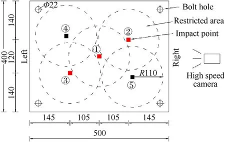
Fig.1.Positions of the impact points of the laminate.
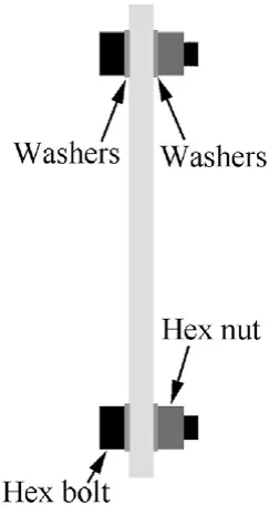
Fig.2.Fixed measures of the laminate.
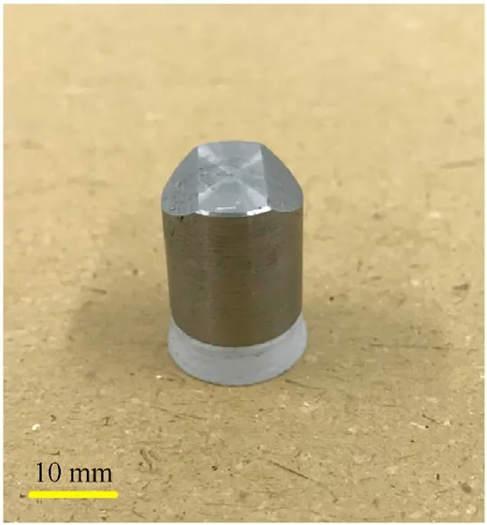
Fig.3.12.7-mm calibre FSP.
The projectiles used in this study are 12.7-mm calibre FSPs that made of 40CrNiMoA steel(Rockwell hardness of 30)with a mass of 13.4 g.The appearance of the wedged-shaped FSP is a reference to GB/T 32,497-2016[36],as shown in Fig.3.The FSP is launched by a ballistic gun with sliding chamber,and different initial projectile velocities can be achieved by adjusting the amount of gunpowder.
2.2.Testing
Fig.4 gives the ballistic testing layout.After the FSP is launched,the initial and residual velocities are measured by a pair of parallel light screens (trigger accuracy: μs) and a high-speed camera(10,000 FPS),respectively.The deformation process of the laminate are also recorded by the high-speed camera.The high-speed camera is placed on the right-hand side of the laminates and is at the same height as the centre of the laminate(Fig.1).As the highspeed camera is only able to observe the pitch of the FSPs in the vertical direction,to verify the yaw of the FSP in the horizontal direction after penetrating the laminates,a wooden board(Fig.5)is placed behind the laminates to capture the flight paths of the FSP.The results in Fig.5 show that the distances between the centres of the adjacent impact areas on the wooden board (~100 mm) are similar to those(110 mm)designed in Fig.1.In addition,there is no evident offset of the impact points in each area (Fig.5,①-③),which indicates that the FPSs almost fly in straight lines after perforation.Thus,the calculated FSP residual velocities through the high-speed camera are reliable.

Fig.4.Set-up of the ballistic test.
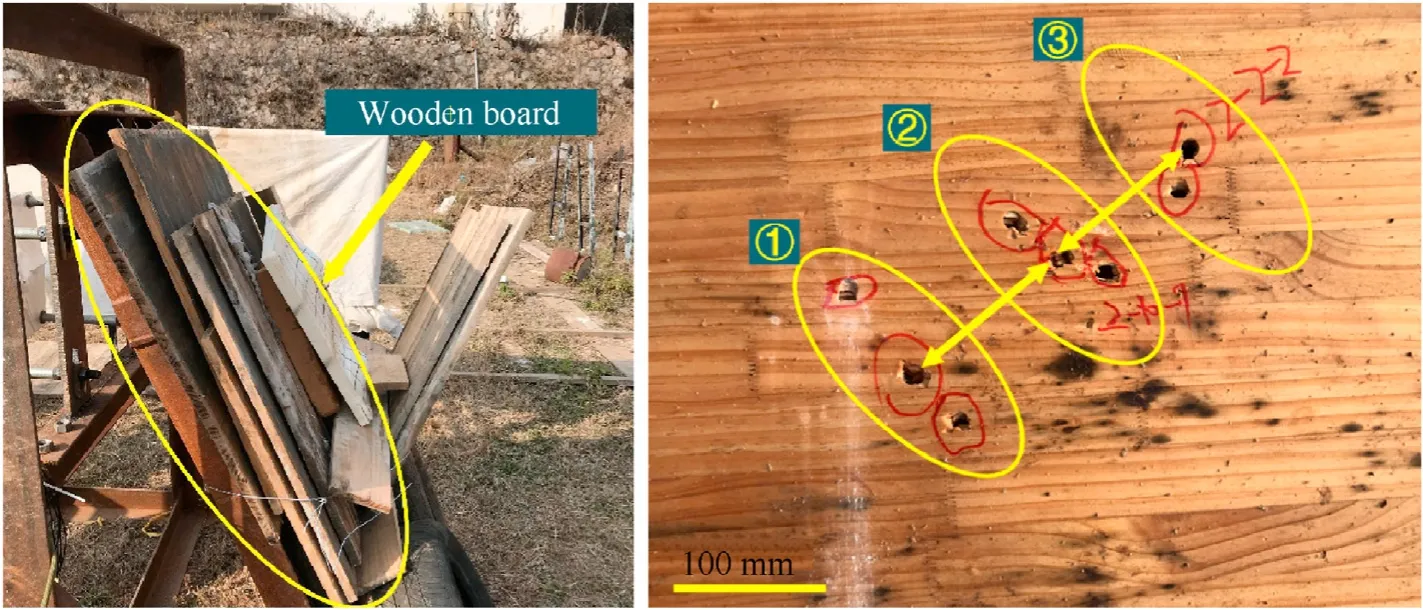
Fig.5.Wooden board and the impact points.
In order to study the anti-penetration mechanism and antipenetration performance of the thick UHMWPE laminates at the same time.The FSP velocities are adjusted to approach the ballistic limits of the laminates through decreasing or increasing the amount of gunpowder,and all the projectile velocities in this study fluctuate within±90 m/s of the ballistic limits.When the difference between the maximum FSP velocity of non-perforation and the minimum FSP velocity of perforation is changing in a very small range(for the 10-,20-,and 30-mm thick laminates were 30,2,and 4 m/s,respectively),it is thought the ballistic limit of the target laminate can be obtained from the average of these two velocities.
3.Results and analysis
3.1.Deformation and failure
3.1.1.Deformation process
The deformation processes of the UHMWPE laminates recorded the second stage(moments 3-5),with the increase of penetration depth,large area BFD and main delamination interface (MDI,delamination that approximately extends to the edges of the laminate) appears (moment 5,and will be shown in detail in subsection 3.1.3),the laminate shows a global deformation and delamination trend.When the 10-mm thick laminate is impacted by FSP at a velocity of 595.9 m/s,the laminate is perforated and it also experiences a two-stage deformation;however,the deformation degree in the second stage(moments 3-5)is relatively smaller.Owing to the rapid perforation process and the high residual velocity of the FSP (442.9 m/s),the BFD area and BFD depth of the laminate decrease significantly compared to those of nonperforation case and no MDI is observed.The advantage of the UHMWPE fibres-absorbing energy through large tensile deformation-is not fully realised at perforation with high projecby the high-speed camera are presented herein,and they are divided into two cases-critical non-perforation and critical perforation-for each laminate thickness,as shown in Table 1.In general,moment 1 and moment 2 represent the pre and initial contact between the projectile and the laminate,respectively.Moment 3 and moment 4 show the penetration process,where moment 4 shows that the laminate just reaches its largest back face deformation (BFD).Moment 5 gives the final penetration results.
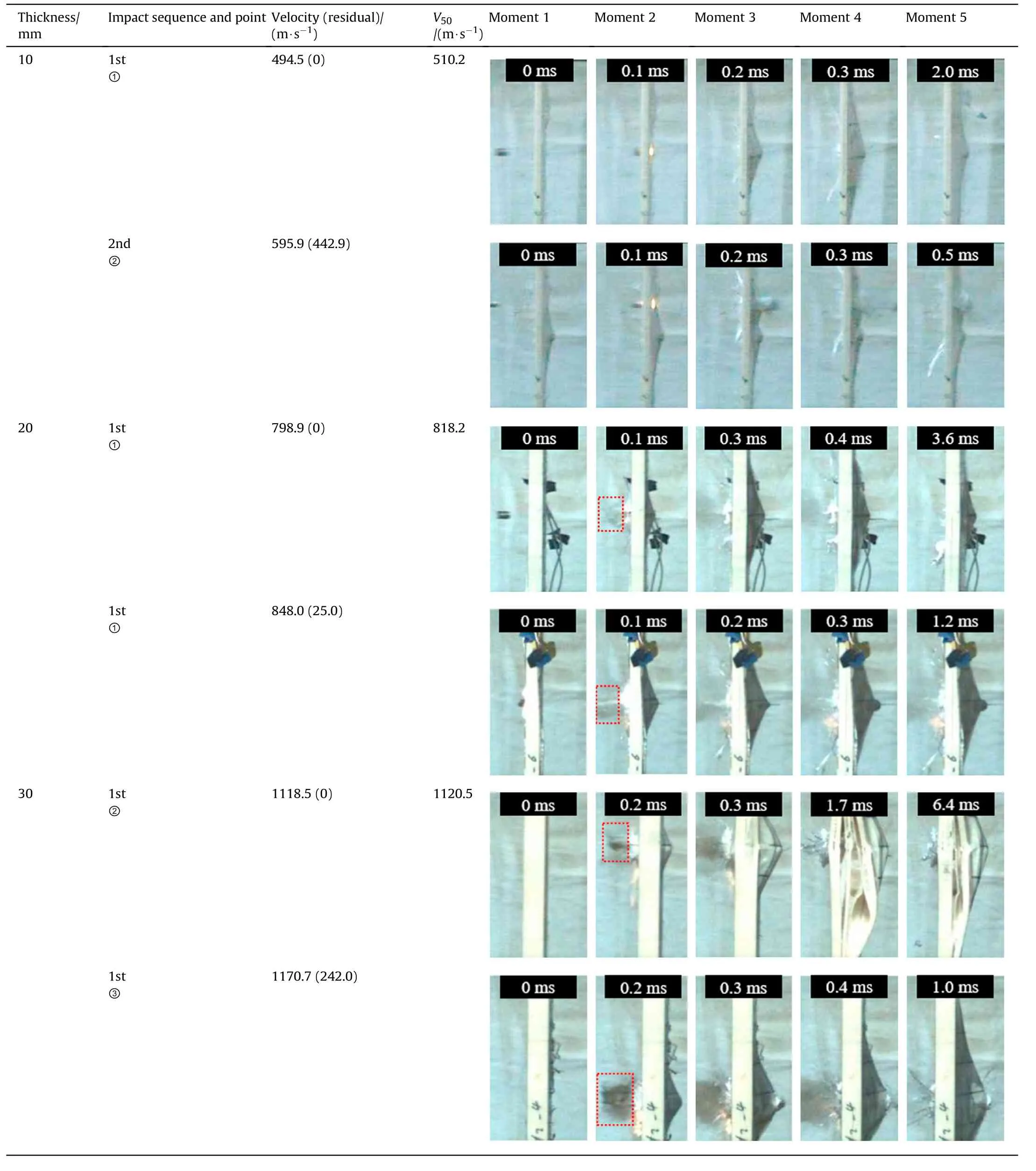
Table 1 Typical deformation and failure process of the laminates with different thickness.
When the 10-mm thick laminate is penetrated by FSP at a velocity of 494.5 m/s,its deformation process can be divided into two stages.In the first stage (moments 1-2),the FSP has not entered into the laminate completely,the laminate is dominated by local damage and no evident BFD is observed(as shown in moment 2).In tile residual velocity.
When the 20-mm thick laminate is impacted by FSP at a velocity of 798.9 m/s,the laminate also experiences a similar two-stage deformation,but it is slightly different from that of the 10-mm thick laminate.In the first stage,brittle shear plugging [28] is more evident due to the fibre and matrix at the impact point are smashed and splashed (as shown in the red box at moment 2).In the second stage(moments 3-5),MDI and large area deformation also appear and the main energy dissipation mode of the laminate is the coupling of delamination and fibre failure.When the 20-mm thick laminate is perforated by FSP at a velocity of 848.0 m/s,breakage occurs and the fibre and matrix are laterally pushed apart at the initial FSP-laminate contact (moment 1),and was also observed by Tomasz[25].Compared to that of non-perforation,the MDI of the perforated 20-mm laminate appears earlier in moment 3.
When the 30-mm thick laminate is impacted by FSP at a velocity of 1118.5 m/s,the laminate generally shows a three-stage characteristic.In the first stage (moments 1-2),brittle failure occurs at the opening hole,the matrix and fibre debris splash out and the colour of these debris becomes darker than those in the 20-mm thick laminates owing to high-temperature ablation.The second damage stage (moments 3-4) of the 30-mm thick laminate is unique.It can be observed from moment 3 to 4 that several successive MDIs extending to the edges of the laminate appear,which are not observed in the 10-and 20-mm thick laminates.The laminas behind the MDIs are pulled from all sides towards the centre of the impact point,which results in severe expansion of the delamination and bulge deformation.In the third stage(moments 5),the FSP is not capable of perforating the laminate,the remaining energy is dissipated through the extension of in-plane delamination and fibre stretching.When the 30-mm thick laminate is impacted by FSP at a velocity of 1170.7 m/s,the laminate is perforated.However,due to the impact point is located at position ③(Fig.1),which is far from the right-hand edge of the laminate,the progressive penetration and delamination failure are not captured by the high-speed camera.This indirectly reveals that the definition of the global and local damage is related to the size of the laminate.Under perforation,the 30-mm thick laminate also experienced three-stage deformation and failure,which will be described in detail in Subsection 3.1.3.
3.1.2.Back face deformation depth
When the FSP velocity exceedsV50of the UHMWPE laminate by approximately tens of metres-per-second,the BFD depth of the laminate reaches its peak value,and the BFD depth in the worst case is selected and analysed conservatively,as shown in Fig.6.The specific FSP velocities for the 10-,20-,and 30-mm thick laminates are 526.0,848.0,and 1153.4 m/s,respectively.In Fig.6,H1represents the maximum BFD depth of the laminate during the FSP-laminate interaction time(IT,time from the warhead contacts the striking face to emerges from the back face),and the values for the 10-,20-,and 30-mm thick laminates are 37.7,31.5,and 50.7 mm,respectively;H2represents the maximum BFD depth of the laminate during the entire deformation process (penetration and free vibration),and the values for the 10-,20-,and 30-mm thick laminates are 37.7,37.9,and 64.1 mm,respectively;H3represents the residual BFD depth of the laminate.
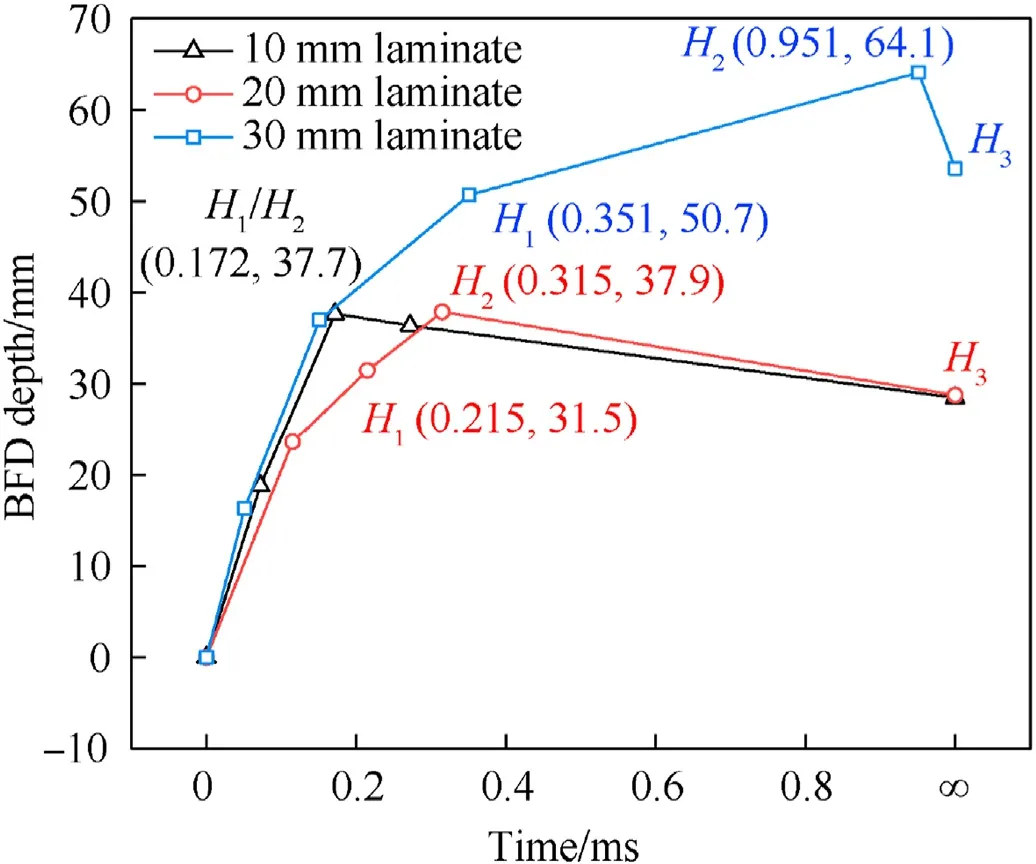
Fig.6.Time history curves of BFD depths of the laminates.
The 10-mm thick UHMWPE laminate has the same values ofH1andH2,indicating that the laminate reaches its maximum BFD depth right at the time of perforation.The gradual decline in the slope of the BFD time history curve in Fig.6 represents a decrease in the projectile velocity during the penetration.After reaching the maximum BFD depth,the BFD depth of the 10-mm thick laminate is reduced by 9.2 mm in the thickness direction,and the residualH3is 28.5 mm.
Due to there is no evident difference in the deformation process of the 20-and 10-mm thick laminates,as illustrated in Table 1,the BFD depth time history of the 20-mm thick laminate is similar to that of the 10-mm thick laminate.However,the value ofH1for the 20-mm thick laminate is slightly smaller than that of the 10-mm thick laminate,which indicates that more critical shearing failure occurred.The 30-mm thick laminate has the largest values ofH1,H2,andH3,and the BFD depth time history curves are significantly different from those of the 10-and 20-mm thick laminates.Firstly,H1for the 30-mm thick laminate is approximately 1.3-1.6 times larger than for the 10-and 20-mm thick laminates.Furthermore,the time interval between theH1andH2of the 30-mm thick laminate is six times larger than that of the 20-mm thick laminate,this implies that the 30-mm thick laminate would experience more severe delamination and in-plane delamination.
It takes 0.019 ms for the FSP to fly freely at a distance of 10 mm at 526.0 m/s while 0.172 ms to perforate a 10-mm thick laminate.The time consumed during the latter situation is 9.1 times longer than the former.Similarly,the perforation time of the 20-mm thick laminate is 9.1 times the free flight time with an FSP velocity of 848.0 m/s.However,for 30-mm thick laminate,this ratio increases to 13.5 times.This indicates that the 10-and 20-mm thick laminates would have similar deformation process and failure characteristics,whereas the 30-mm thick laminates would be different.
3.1.3.Failure analysis
The final penetration failure states of the laminates are shown herein.For the 10-mm thick laminate,it can be observed from Fig.7(a) that the diameter of the holes on the strike face is approximately the same as that of FSP,and there is slight fibre eversion phenomenon at the openings.As shown in Fig.7(b),due to the unidirectional reinforcement and orthogonal stacking sequence of UHMWPE laminas,diamond-shaped bulge areas are formed.However,the adjacent ranges of the bulges are not linked.For the 10-mm thick laminate,the failure characteristics show high similarity under three shots when the velocities of the FSP are approximately 500 m/s.Similar phenomena also appear in the 20-mm thick laminate (FSP:~800 m/s) and 30-mm thick laminates(FSP:~1100 m/s).Succinctly,the failure analysis of one shot can be a reasonable reference for three shots of the 20-or 30-mm thick laminates.
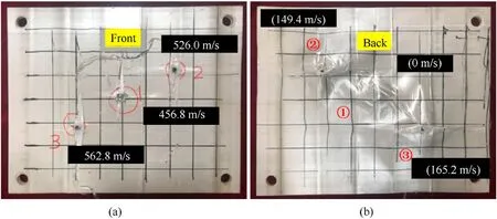
Fig.7.Failure characteristics of the 10-mm thick laminate: (a) Strike face and impact velocity;(b) Back face and residual velocity.
As shown in Fig.8(a(2)),evident fibre eversion on the front face is observed for the 20-mm thick laminate.There is no significant difference in the back face deformation and failure between the 10-and 20-mm thick laminates,the diagonal length of the diamondshaped BFD is about 100 mm (the square lattice length on the laminate is 50 mm),as shown in Fig.8(b(1))and Fig.8(b(2)).For the 30-mm thick laminate,with the increase of laminate thickness and FSP velocity,more significant brittle failure and fibre eversion occur on the strike face (Fig.8(a(1))).Owing to the severe delamination failure,the BFD area of the 30-mm thick laminate is larger than and approximately 1.5-2 times those of the 10-and 20-mm thick laminates,as shown in Fig.8(b(3)).During the penetration of the 30-mm thick laminate,the FSP began to undergo slight plastic deformation,which would result in minute degradation of its penetration performance.
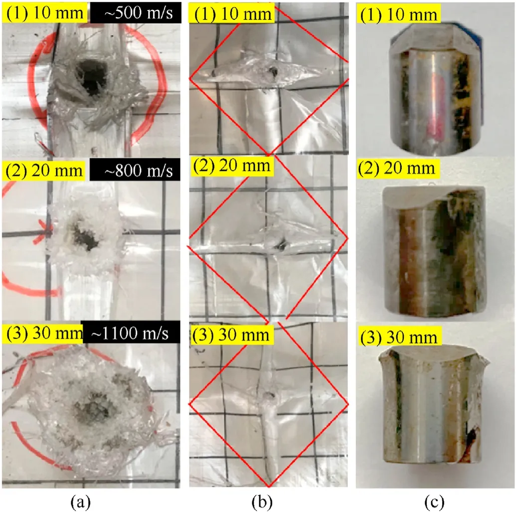
Fig.8.Failure characteristics of the laminates and FSPs: (a) Strike face;(b) Back face;(c) FSP.
Water jet cutting technique is utilised to obtain the real penetration cross-section of thick UHMWPE laminates.It is experimentally found that the ballistic performance of the UHMWPE laminate varies most significantly around its ballistic limit,thus two cases of critical non-perforation (Fig.9(a)) and critical perforation (Fig.9(b)) are selected for investigation.As shown in Fig.9(a(1)),when the FSP velocity is close to but slightly lower than the ballistic limit of the 10-mm thick laminate,the laminate mainly experiences shear failure.The opening diameter penetrated by the FSP is uniform,and the sidewall of the opening is straight and smooth.The penetrating depth of the 10-mm thick laminate is approximately 7.1 mm when the FSP velocity was 456.8 m/s.When the FSP velocity increased to 526.0 m/s,the 10-mm thick laminate is perforated and shows typical two-stage failure characteristics,as shown in Fig.9(b(1)).Shear plugging failure with uniform opening diameter occurs first,while in the second stage,the laminate experienced large BFD and fibre tension.Moreover,a large MDI that divides the failure from local to global is observed in the laminate,this is caused by the penetration resistance of the back-part laminate that exceeds the interface bonding property between laminas.In comparison to the case when the FSP velocity is slightly lower than the ballistic limit,the delamination and BFD of the laminate at this time are greater and more concentrated,the integrity of each part (stages one and two)of the laminate was well preserved.
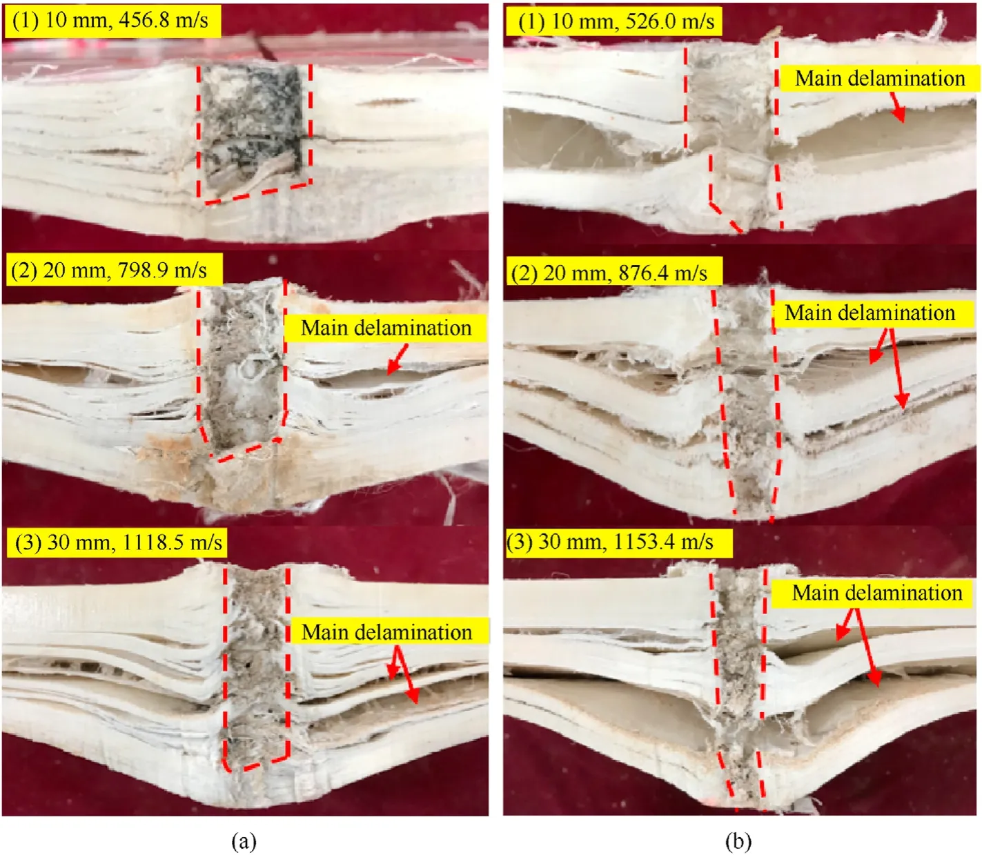
Fig.9.Penetrating failure section of the UHMWPE laminates: (a) Non-perforation;(b) Perforation.
Fig.9(a(2)) and Fig.9(a(3)) give the cross-sections of the nonperforated 20-and 30-mm thick laminates at FSP velocities of 798.9 and 1118.5 m/s,respectively.And their respective penetration depths are 13.4 and 24.8 mm.It can be observed that when the projectile velocities are slightly lower than the ballistic limits,the 20-and 30-mm thick laminates are dominated by shear failure,and the opening diameters are even across the penetration path.Large number of discrete delamination areas can be observed around the opening holes,similar to those of the 10-mm thick laminates.However,owing to the increase in the laminate thickness and the FSP velocity,one MDI begins to appear in the 20-mm thick laminate and two appear in the 30-mm thick laminate.This indicates that thick UHMWPE laminate is more likely to produce spalling failure in its critical non-perforation state.When the FSP velocities are slightly greater than the ballistic limits,the 20-and 30-mm thick laminates experience typical three-stage penetration and delamination failure,as shown in Fig.9(b(2))and Fig.9(a(3)).Before the first MDI(close to the strike face),the laminates mainly experience shear plugging failure.Between the first and the second MDI,the opening diameters gradually become smaller and the laminas began to bulge,the middle-part laminates experience tension shear coupling failure.Behind the second MDI,the opening diameters continue to decrease and the BFD degree of the laminates become more significant.For the 20-mm thick laminates,regardless of whether the FSP velocities are slightly lower or higher than the ballistic limit,the locations of the MDIs are all near the middle of the thickness direction,and the damage of the first MDI is more evident.For the 30-mm thick laminates,the MDIs are more backward,and the second MDI is the dominant failure interface,the large BFD depth of the 30-mm thick laminate shown in Fig.6 is mainly caused by the lamina deformation behind the second MDI.
3.2.Ballistic performance
3.2.1.Ballistic limit
The experimental FSP velocities and ballistic limits of the UHMWPE laminates are listed in Table 2.The average value method is used to calculateV50of the UHMWPE laminates.Two FSP initial velocitiesViwith the closest value were selected and averaged.One of these two velocities,Vip,is the minimum velocity of perforating the laminate and the other one,Vis,is the maximum velocity of non-perforating the laminate.According to a standard [36],when the difference ofVipandVisis less than 15 m/s,the average of these two values can be regarded as the potentialV50of the laminate.Therefore,the calculated ballistic limits of the 20-and 30-mm thick laminates are 818.2 m/s and 1120.5 m/s,respectively,and the largest coefficients of variation (CoV) of the ballistic limit is 4.3%.TheV50of the 10-mm thick laminate calculated through the average value method is 510.2 m/s,although it does not meet the requirement noted above [36] (the difference ofVipandViswas 31.5 m/s);its accuracy and reliability is verified by the Lambert-Jonas equation (also known as the Recht-Ipson equation[37]).Lambert-Jonas equation has been proven to have strong robustness in predicting the ballistic limit for different materials[38].TheV50calculated through the Lambert-Jonas equation is 515.9 m/s,which is very close to 510.2 m/s and the difference is less than 1.2% and could be ignored.Thus,theV50of the 10-mm thick laminate is taken as 510.2 m/s,and the CoV of the 10-mm thick laminate is approximately 3.2%.

Table 2 Experimental FSP velocities and ballistic limits of the UHMWPE laminates.
Average values method
Lambert-Jonas equation
where α is a curve fitting parameter,and has a value of 1.23061 in this study.
whereV1,ipis the minimum FSP velocity of perforation,and should be the first shot of the laminates to ensure conservative.For the 10-20-and 30-mm thick UHMWPE laminates,the values ofV1,ipare 526.0 (approximate value),848.0 and 1170.7 m/s,respectively.
3.2.2.Energy absorption efficiency
When the 10-mm thick UHMWPE laminate is non-perforated,the energy dissipated by the laminate increases monotonically with the increase of FSP velocity,as shown in Fig.10(a).However,the maximum energy absorption is not atV50,there is an increase of approximately 5-15% when the FSP velocity is slightly higher thanV50.In this study,the authors propose a concept called energy limit,this concept corresponds to the peak value of the energy absorption and represents the maximum energy absorption capacity of the laminate.The energy limit,to some extent,verified the authenticity of the results that the BFD depth of the UHMWPE laminates reached its peak value at projectile velocities are tens of metres-per-second higher thanV50,as illustrated in Subsection 3.1.2.The 10-mm thick laminate reached its energy limit of approximately 1939.9 J when the FSP velocity was 562.8 m/s,and the energy absorption at this time was 10% higher than that atV50.For the 20-mm thick laminate,the energy limit was not captured in the test owing to the limited number of shots.However,there may be an increase more than 14% in energy absorption at its energy limit in comparison toV50,as shown in Fig.10(b).After perforation,there is a sudden increase in the FSP residual velocity,which is also true for the 30-mm thick laminates,this seems to be unique performance of the thick UHMWPE laminate that the ballistic performance is prone to fluctuate near critical perforation,and needs further studied.For the 30-mm thick laminate,the energy limit is approximately 5% higher thanEbl.The difference between the energy limits andEblof the 30-mm thick laminates becomes smaller than those of the 10-and 20-mm thick laminates,this is because the absolute value ofEblbecomes larger,resulting in a smaller proportion of the difference.
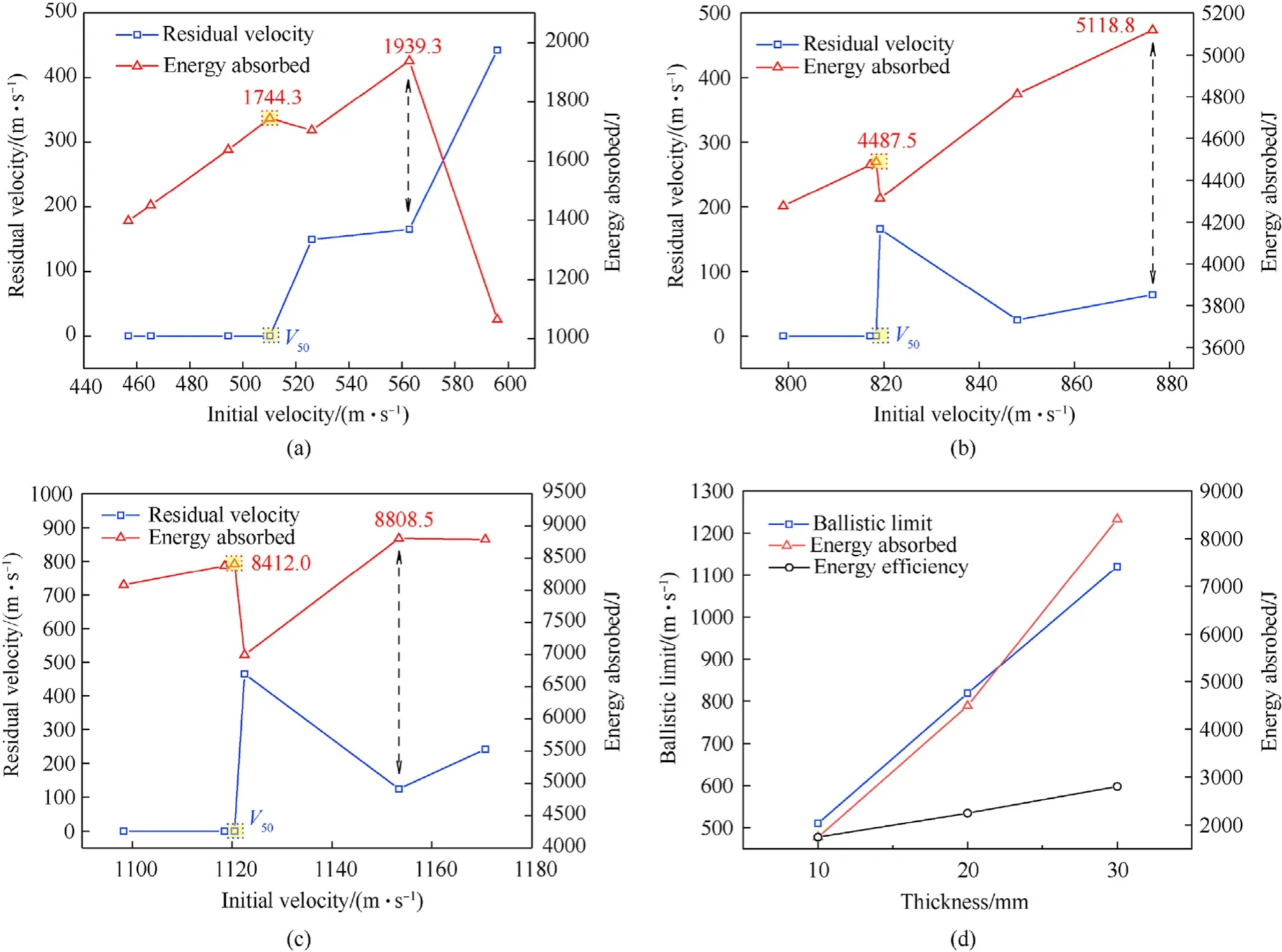
Fig.10.Residual velocities of the FSPs and the energy absorption of the laminates: (a) 10-mm thick;(b) 20-mm thick;(c) 30 mm-thick;(d) Comparison.
Before perforation,the maximum energy absorbed by the 10-,20-,and 30-mm thick laminates are 1744.3,4487.5,and 8412.0 J,respectively,and the normalised values are 1.0,2.6,and 4.8,respectively.The normalised energy absorption efficiency per unit thickness of the 10-,20-,and 30-mm thick laminates are 1.0,1.3,and 1.6,respectively.This indicates that the thicker the laminate,the higher its protective efficiency.This is also true for the energy limit.When the FSP initial velocity is lower than that at energy limit,the energy dissipation generally increases with the projectile velocity,and the UHMWPE laminate could give full play to its protective performance.However,when the FSP initial velocity is higher than that at energy limit,the energy dissipation efficiency decreases (probably sharply,as shown in Fig.10(a)) with the increase of the FSP velocity,and the laminate would lose its ballistic advantage.As demonstrated in Fig.10(d),under the penetration of 12.7-mm FSPs,there is approximately a linear positive correlation betweenV50and the laminate thickness,and thus the energy absorption of the UHMWPE laminate approximately has a quadratic relationship with the laminate thickness.
4.Discussion
According to the testing observation,thick UHMWPE laminates have large-area delamination trend which would produce predamage of next shot,however,the analysis results show that the existence of pre-damage of the laminates will not lead to significant deviation in the laminate ballistic performance,but within an acceptable range (less than 5%).This means that the testing procedure designed according to standard GB/T 32,497-2016 [36] is reasonable,and the testing results are reliable.For the 10-and 20-mm thick laminates,there are surpluses greater than 10% at energy limits compared toEbl.The energy absorption efficiency of the laminate could be fully exploited in sandwich structures.For the 30 mm thick laminate,there is no significant difference between energy limit andEbl,thus,the ballistic limit could be taken as an indicator in bulletproof design.Due to the sudden increase of FSP residual velocities after just perforating the 20-and 30-mm thick laminates,the ballistic design of thick laminates should be conservative.
The staged penetration process and severe delamination are unique for thick UHMWPE laminates,and provides the thick laminates with outstanding energy absorption capacity superior to thin UHMWPE laminate.When the FSP velocity is close to the ballistic limit,the BFD depth of the laminates exceeded the value of 25 mm,as specified in standard [39] that is stipulated for body armour.Therefore,to prevent blunt damage,an optimal design should be considered when the UHMWPE laminates are designed to defend the high-speed penetration,such as employing multiple material structures [40,41].Moreover,under the influence of the large deformation and large delamination,the risk of spalling occurs in the back part of the thick laminates,as shown in Fig.11.Therefore,to keep the integrity of the laminate,more attention should be paid to the reliability of the boundary constraints of the laminates.When the 20-and 30-mm thick laminates are impacted by FSPs at velocities higher than the ballistic limits,the integrity of the corresponding part laminates in each penetration stage is well preserved (Fig.9(b(2)) and Fig.9(b(3)).A suggestion can be taken to reuse the penetrated laminates by swapping the front and back faces.The former back part laminates are therefore arranged to experience local shear plugging failure,while the former slightly deformed front faces are arranged as new back faces to experience bulge deformation and delamination.In particular,the idea of reusing is more suitable for the thick laminate because its MDIs are more backward and it has a thicker part of non-delaminated laminate,as illustrated in Fig.9.It can be deduced that the greater the FSP velocity,the more backward the MDIs of the laminate.Therefore,the idea of reusing is more suitable for thick UHMWPE laminate after high-speed penetration.
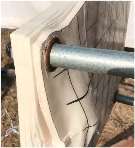
Fig.11.Spalling of the thick UHMWPE laminates.
5.Conclusions
Multi-stage penetration characteristics of thick UHMWPE laminates against 12.7-mm calibre FSP at velocities of 450-1200 m/s are researched.The main conclusions are as follows:
(1) The ballistic limits of the 10-,20-,and 30-mm thick laminates are 510.2,818.2,and 1120.5 m/s,respectively,and the ballistic limit increases approximately linearly with the laminate thickness.When the FSP velocity reaches the ballistic limit,the normalised energy absorption efficiencies of the 10-,20-,and 30-mm thick laminates are 1.0,1.3,and 1.6,respectively.
(2) The 10-mm thick laminate shows two-stage failure characteristics of shear plugging first,bulge deformation and delamination.However,the 20-and 30-mm thick laminates experience more staged penetration process which is influenced by the FSP velocity.Large-area back face deformation and staged delamination are the keys to energy dissipation of thick UHMWPE laminate.
(3) The maximum BFD depths of the 10-,20-,and 30-mm thick UHMWPE laminates in this research are 37.7,31.5,and 50.7 mm,respectively,which exceed the standard requirements for blunt injury prevention.Thick UHMWPE laminate with single material has limits for defending highspeed steel projectiles,therefore,the multi-material bulletproof plates or sandwich structures are worthy of study in the future.
Declaration of competing interest
The authors declare that they have no known competing financial interests or personal relationships that could have appeared to influence the work reported in this paper.
Acknowledgements
The authors acknowledge the financial support from National Natural Science Foundation of China (Grant No.51978166),National Key Research and Development Program of China(Grant No.2019YFC0706105,2021YFC3100703) and the Fundamental Research Funds for the Central Universities (Grant No.2242022R10124s).
杂志排行
Defence Technology的其它文章
- An energetic nano-fiber composite based on polystyrene and 1,3,5-trinitro-1,3,5-triazinane fabricated via electrospinning technique
- Dynamic response of UHMWPE plates under combined shock and fragment loading
- Aerial multi-spectral AI-based detection system for unexploded ordnance
- Model-based deep learning for fiber bundle infrared image restoration
- Robust design and analysis for opto-mechanical two array laser warning system
- Combustion behavior and mechanism of molecular perovskite energetic material DAP-4-based composites with metal fuel Al
