Plasma transport simulation under different conditions and optimization analysis of dual-stage grid ion thruster
2023-09-05YajieHANGuangqingXIABinSUNChangLUJunjunZHANGVlaimirSAETCHNIKOV
Yajie HAN, Guangqing XIA,c,*, Bin SUN, Chang LU,c,Junjun ZHANG, Vlaimir A.SAETCHNIKOV
a State Key Laboratory of Structural Analysis, Optimization and CAE Software for Industrial Equipment, Dalian University of Technology, Dalian 116024, China
b Key Laboratory of Advanced Technology for Aerospace Vehicles of Liaoning Province, Dalian University of Technology,Dalian 116024, China
c Collaborative Innovation Center of Micro & Nano Satellites of Hebei Province, North China Institute of Aerospace Engineering, Langfang 065000, China
d Physics and Aerospace Technology Department, Belarusian State University, Minsk 220030, Belarus
KEYWORDS 3D modeling;Dual-stage grid;Ion thruster;PIC/MCC method;Plasma simulation
Abstract In order to study the extraction and acceleration mechanism of the dual-stage grid, a three-dimensional model based on the Particle-In-Cell/Monte Carlo Collision(PIC/MCC)method is performed.Dual-stage grid ion thruster is a new type of electrostatic ion thruster, which can break through the limitations of traditional gridded ion thrusters, and greatly improve the specific impulse.The high performance also makes the grid sensitive to operating parameters.In this paper,the influence of grid parameters on xenon ion thruster’s performance in a wide range is systematically simulated,and the optimal operating condition is given.Both the over-focusing of the plume,and the transparency of the screen grid are improved, and the grid corrosion is reduced through simulation optimization.The specific impulse under the given working conditions is 9877.24 s and the thrust is 7.28 mN.Based on the simulation optimization, the limitation of the dual-stage grid is discussed.The grid performs well under high voltage conditions (>3000 V) but not well under low voltage conditions (<2000 V).Finally, since argon is cheaper and more advantageous in future engineering applications, the plasma distribution and grid extraction ability under xenon and argon are analyzed and compared to study the flexibility of the dual-stage grid ion thruster.The simulation results show that a set of optimal parameters is only applicable to the corresponding propellant, which needs to be optimized for different propellant types.
1.Introduction
The burgeoning development of air space industry gives rise to the propulsion technology.In such a context, electric propulsion technology has been given a new historical mission of moving toward high power, high thrust, and high specific impulse.1,2The dual-stage grid ion thruster3as a new type of electric propulsion technology can greatly improve the performance of specific impulses,and has been widely used in the development of ion thrusters.The traditional grid system is mainly composed of a screen grid, an acceleration grid and a deceleration grid.The extraction and acceleration of ions are all realized between the screen grid and the acceleration grid,meanwhile restrict the thruster’s development to a higher specific impulse.To overcome this defect, the concept of a dual-stage grid system has been proposed by adding an extraction grid between the screen grid and the acceleration grid to separate the extracting and accelerating processes.Up to now, there are two types of dual-stage grid system based on whether to include deceleration grid namely Dual Stage 4 Grid(DS4G) and Dual Stage 3 Grid (DS3G).
Inspired by a Controlled Thermonuclear Reactor (CTR)experiment, Fearn proposed the concept of dual-stage grid.3The DS4G principle prototype is shown in Fig.1.The European National University and the European Space Agency first developed the DS4G ion thruster and successfully tested it in space simulation cabins in 2005.4

Fig.1 DS4G principle prototype.
With the introduction of the ESA HiPER program,5many scholars have begun to study new electric propulsion technology.In 2010, Coletti et al.optimized the design of the DS4G and developed the DS3G ion thruster.6They proposed to remove the deceleration grid that exists only as a zero potential in the DS4G.The main functions of the deceleration grid are to limit the corrosion caused by Charge Exchange(CEX) ions downstream and prevent aperture-groove corrosion, the same as traditional grid system.Goebel and Katz proposed that although the life of a traditional three-grid system is longer than that of a two-grid system, this advantage is offset by the complexity of the grid including the third grid.7Coletti et al.6believed that this principle is also applicable to the DS3G thruster, which greatly reduces the complexity of thrusters.
Jia et al.8,9simulated the dual-stage system using a 2D model, focusing on the design of the accelerating grid voltage.The optimized acceleration grid voltage 250 V is determined by numerical simulation and verified by experiments.But the grid structure they used is mainly designed with reference to the traditional grid system, whose particularities are not considered.And 2D model cannot accurately study the grid corrosion as well.Due to the particularity of the structure, the dual-stage grid system cannot be designed exactly in accordance with the traditional grid system design method.It is necessary to study the movement of plasma during the extracting and accelerating stages by 3D numerical simulation.
There are still many deficiencies in the current research on this thruster.First of all, in the actual working process of the thruster, the range of working conditions varies greatly, and it is necessary to carry out systematic parameter analysis and optimization.Second, the grids of traditional thrusters usually operate at lower voltages, and whether the dualstage grid can completely replace the traditional grid has not been thoroughly discussed.Finally, there is no relevant report on the performance research under different propellant conditions.
In order to solve these problems, this paper establishes a three-dimensional PIC/MCC simulation model using parallel algorithm,using Xe as propellant,studies the plasma transport in the dual-stage grid ion thruster, and obtains the optimal working conditions under which the ultra-high specific impulse(~10000 s)can be achieved.Among them,since the mass ratio of ions to electrons is very different, we treat the electrons as fluids according to the classical grid calculation model.10Furthermore, the limitations of the thruster are studied, and its performance under traditional grid voltage conditions is analyzed.In addition, Ar is usually selected as the propellant in the laboratory,Xe and Ar propellants are simulated and compared for studying the flexibility of ion thruster.

Fig.2 Basic flowchart of PIC algorithm.
2.3D PIC/MCC simulation method
2.1.Basic theory of PIC method
The core idea of the PIC method is to track the motion of each ‘‘macro particle”.Fig.2 shows the basic flowchart of the PIC method under electrostatic field condition, where nidenotes the ion density, nedenotes the electron density, T denotes the particle temperature, Ejand ρjdenote the electric field intensity and charge density at the mesh nodes respectively, Fidenotes the force acting on particles, viand xidenote the velocity and position of particles respectively.The calculation program is mainly divided into two parts: one is to obtain the spatial distribution of the electrostatic field by solving Maxwell’s equations; the other is to calculate the motion trajectories of macro particles in the electrostatic field according to Newton’s second law.This method is widely used in numerical simulation researches of electric propulsion.
The motion of macro particles is described by

Fig.3 ‘‘Leap-frog”format.
where m denotes the mass of the particle, v denotes the velocity of the particle, q denotes the amount of charge,E denotes the electric field intensity and x denotes the position of particle.The Boris ‘‘leap-frog”11format is usually used to solve the motion of ions.The solution idea is shown in Fig.3.
2.2.Collision processing method
The PIC method describes the motion state of particles under the action of a physical field.In an actual highdensity plasma environment, charged particles always collide with others.The collision type is mainly divided into longdistance coulomb collision and short-distance elastic collision.When using the PIC method for collision processing,the Monte Carlo Collision (MCC) method is used for description.The MCC method can describe the collision between the target particle and the background particle,and can also be used to describe the collision with other types of particles.In this paper, elastic collision and CEX collision are considered, which are generally considered in grid simulation,12,13and the collision cross-sections of different propellants are shown below:
(1) Xe collision cross-section:13

where ε is the energy of the target ion.

Fig.4 Schematic diagram of iteration direction.
2.3.3D parallel algorithm
In order to speed up the solution of the electric field,this paper utilizes a parallelized 3D Finite Difference Method (FDM)15to solve the Poisson equation.Consider the threedimensional Poisson equation on the cuboid region,
where Ω= [0,L]× [0,M]× [0,N]is the solution domain,∂Ω is the boundary of Ω, φ(x,y,z)is the function to be sought, and f (x,y,z)and g(x,y,z)are known as smooth functions.
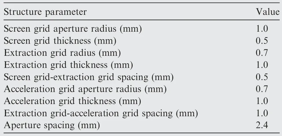
Table 1 Grid structure parameters.
The three-dimensional computational domain is divided into eight computational sub-domains by appropriate partitioning.The 3D Poisson equation can be explicitly parallel solved using different iterative formats in different domains.15Fig.4 shows the iteration direction of different time steps.In odd time steps, iterate from the periphery to the center of the computational domains.In even time steps, iterate from the center of the computational domains to the periphery.By using the 3D parallel algorithm,the efficiency of the calculation program can be greatly improved.
3.Calculation model
3.1.Physical model and computational domain
The initial calculation structure parameters of the grid are set by referring to the prototype of the DS3G thruster of Southampton University,16as shown in Table 1.The grid apertures are uniformly opened in a region with a radius of 2.5 cm in the center of the grid plate.According to the symmetry of the grid aperture structure, only 1/4 grid aperture is taken as the computational domain, as shown in Fig.5.Fig.5(a) shows the three-dimensional structure of a single complete grid aperture; Fig.5(b) shows the left view of the computational domain.
According to the electron cyclotron resonance discharge simulation,17the plasma density in the discharge chamber is in order of magnitude of 1017m-3.In this paper, the plasma density n of the discharge chamber is 2.5 × 10¹⁷m-3, which means that ion number density at the inlet boundary can be calculated with equation n0= 0.6065n, and the electron temperature Te0in the discharge chamber is 5 eV.The mesh size Δh of the space satisfies the constraint of the Debye length λD:λD/Δh ≥1/π.11
Therefore,the size of the mesh is taken as 5×10⁻⁵m in the simulation, and the entire computational domain is divided into 24 × 42 × 142 orthogonal meshes.To facilitate the description of the boundary conditions, the z-x 2D section is shown in Fig.6.According to the Courant Friedrichs Lewy(CFL) condition: vmaxΔt < min(Δx, Δy, Δz) and vmaxis set to 105m/s, the time step can be further obtained as Δt = 5×10⁻¹⁰s.

Fig.5 Computational domain setting.

Fig.6 Computational-domain 2D section meshing.
The boundary conditions are set as follows:
(1) Inlet boundary

(2) Outlet boundary
The right boundary is outlet boundary in Fig.6.When the ion moves away from the outlet boundary, it is treated as an escape and the particle information is deleted.The outlet boundary surface is located away from the grid system, and its potential is fixed at 0 V.
(3) Symmetrical boundary
The up and down boundaries are symmetrical boundary in Fig.6.On the symmetry boundary surface, the electric field along the plane of symmetry is zero.When the ion moves beyond the symmetry plane,it is treated as specular reflection.
(4) Wall boundary
The grids are wall boundary.The potential of screen grid,extraction grid and acceleration grid are denoted as φsc,φextand φacc, respectively and the electric field intensity inside the grid is 0 V/m.When the ions hit the grid surface, the ion current is accumulated and the particle information is deleted.
3.2.Plasma description
This model mainly studies the motion of ions in the dual-stage grid system.If electrons are considered in the particle dynamic way,the mesh size and the time step should be about one thousandth of the ion’s time step.This will lead to a significant increase in the amount of calculation and time.Therefore,electrons are treated as fluids in this model,and electron density is subject to the Boltzmann distribution.18The electrons in the computational domain are only considered in two regions:the high-energy electrons in the sheath of the discharge chamber upstream of the screen grid, and the electrons emitted by the neutralizer in the downstream plume region of the acceleration grid.
In the screen hole and its upstream area:
where n0, φ0and Te0represent the reference number density,potential and electron temperature in the upstream discharge chamber, respectively.
In the acceleration grid aperture and its downstream area:
where n∞,φ∞and Te∞represent the reference number density,potential and electron temperature in the plume region downstream of the acceleration grid, respectively.The reference downstream plasma number density n∞is the average value of the ion number density in the downstream region of the acceleration grid for each calculation time step and φ∞=0 V,Te∞=1.5 eV.
Xenon gas is selected as the propellant.During each time step,xenon ions are injected at a Bohm velocity from the upper boundary of the screen into the calculation region.
The ion enters the grid through the sheath, and its axial velocity is calculated according to the Bohm criterion.19The ion radial velocity obeys the Maxwell distribution.The movements of ions in the electric field are described using the‘‘frog leap”.10
For neutral atoms, the velocity is much lower than that of the ion,and the influence on the plasma is small.Therefore,the neutral particle motion is not considered in the simulation.Assume that it is an ideal gas, which obeys the ideal gas law Pn= nnkTn, where Tn= 500 K is neutral temperature, nnis neutral density and Pn= 0.01 Pa is neutral pressure.
3.3.Grid voltage setting
The expected specific impulse value is set to 10000 s.According to the specific impulse calculation, as shown in Eq.(9), the required acceleration voltage can be obtained as 6534 V.By referring to the structure and performance parameters of the foreign DS3G thruster, the initial screen voltage is 6294 V,the extraction grid voltage is 4294 V,and the acceleration grid voltage is -120 V.
where V is acceleration voltage,mXeis mass of xenon ion,g is gravitational acceleration.
The three-dimensional computational domain is divided into eight computational sub-domains by appropriate partitioning.
4.Simulation results and discussion
4.1.Plasma transport simulation

Fig.7 Plasma transport parameter distribution.

Fig.8 Two-dimensional cross-section potential distribution.
The initial calculation model utilizes Xe as the propellant to acquire data after the plasma moves in the grid system to a steady state.By using the PIC method, the following plasma transport parameter distributions are obtained, as shown in Fig.7.
It can be seen from Fig.7 that the simulation program can well simulate the motion process of the plasma transport phase, and can reflect the actual flow field distribution.The axial electric field between the grids is large so that plasma can be accelerated faster.At the same time,it can be seen that there is a certain concentration of ion number density near the axis,which will increase the plume divergence angle and reduce the performance of the thruster.It is necessary to study the influence of electric potential and grid structure on it.
Fig.8 shows the potential distribution of the twodimensional cross-section of the thruster.It can be seen that the sheath area upstream of the grid system is simulated, and the downstream zero equipotential surface is also far away from the acceleration grid,which can be prevented to a certain extent.The electrons flow back into the grid system to make up for the lack of a deceleration grid.

Fig.9 Distribution of potential along axis at different radial positions.
The potential value is less than 0 V at the axis of the grid aperture downstream of the acceleration grid, and a ‘‘saddle point”appears.It can suppress the electron reflow well and meet the requirements of the thruster performance.Fig.9 shows the distribution curve of the potential along the axis at the upper boundary (x = xmax) and the lower boundary(x=0 m)of the simulation area.At the lower boundary,there is a significant potential drop from the right end of the screen grid to the acceleration grid,which produces a large axial electric field that accelerates the ions to a higher velocity.
4.2.Grid system structure optimization
4.2.1.Initial performance parameters
The performance of the grid system is mainly evaluated by the thrust, specific impulse, and the divergence angle loss.We obtain these performance parameters by counting the particles data at the exit of the computational domain when the simulation reaches steady state.Specifically, for specific impulse:where Fxis the x-axis component of thrust,and Fyis the y-axis component of thrust.


Table 2 Initial performance parameters.
Through the preliminary-three-dimensional PIC simulation of the dual-stage grid system, the initial performance parameters are shown in Table 2.It can be seen that the performance parameters under the initial conditions are basically in line with the theoretical calculation values, such as the specific impulse,which also confirms the correctness of the calculation model.
As mentioned above, the ion beam collimation is acceptable,but the axial density is relatively high,and the maximum density is even more than 6 × 10¹⁷m-3.The excessively high axial density indicates that the beam focusing performance is not ideal.The high performance of the thruster makes the grid sensitive to operating parameters.In this paper, the influence of grid parameters on performance in a wide range is systematically simulated.Since the grid structure(including grid aperture size, grid thickness, grid spacing, etc.) and grid potential distribution are important factors affecting the potential distribution, ion extraction and acceleration of the grid system, the grid structure and voltage parameters are optimized and improved.At the same time, the grid transparency, which is the ratio of the number of ions passing through the grid to the number of ions reaching the grid, is also of our concern.Calculate and analyze the plasma distribution under different parameters.The improved objectives mainly include:
(1) Reduce the beam ion number density to improve overfocusing.
(2) Increase the screen grid transparency and enhance beam performance.
(3) Increase the thrust and specific impulse while the acceleration voltage is essentially constant.
4.2.2.Influence of grid aperture
Since the screen grid size will affect the feature size of the entire grid system, it remains unchanged from the DS3G thruster,and the change rule of thruster performance parameters is studied by changing the dimensions of the extraction grid and the acceleration grid.
(1) Change aperture of extraction grid
For the initial thruster operating conditions, the ion beam transport process under different extraction grid radiuses is simulated.The performance of the thruster is shown in Table 3.It can be seen from Table 3 that as the radius of the extraction grid increases,the thrust and specific impulse first decrease and then increase, which will slightly affect the grid transparency.However, the reduction of the extraction grid current means that the number of particles hitting the extraction grid is reduced, which can reduce the corrosion of the grid.By comprehensive consideration, choosing the extraction grid radius to be 0.6 mm can greatly increase the thrust and specific impulse of the thruster,increase the grid transparency,and will not affect the grid life too much.
(2) Change aperture of acceleration grid
Since the acceleration grid is greatly affected by the plume divergence angle,the initial acceleration grid current value has reached 3.11×10⁻⁴A,so only the increase of the acceleration grid aperture is simulated.The thruster performance is shown in Table 4.It can be seen from Table 4 that as the radius of the acceleration grid increases, the thrust and specific impulse change little, and the current value of the acceleration grid gradually decreases, which is in line with the expected goal,but the grid transparency gradually decreases.Therefore, the acceleration grid is selected as 0.8 mm after comprehensive consideration.
4.2.3.Influence of grid thickness
Based on the optimization of the grid aperture,the influence of different extraction grid thickness and acceleration grid thickness on the performance of the thruster is studied respectively.
(1) Change thickness of extraction grid
Based on the optimization of the grid aperture,the thruster performance is shown in Table 5.From the simulation results,it can be found that the change in the thickness of the extraction grid mainly causes corrosion of the acceleration grid, so the acceleration grid current value is counted.It can be seen from Table 5 that as the thickness of the extraction grid increases, the thrust and specific impulse gradually increase,and the divergence angle gradually decreases, but the accelerating grid current value increases significantly.By comprehensive consideration, the thickness of the extraction grid is selected to be unchanged at 1.0 mm.
(2) Change thickness of acceleration grid
Similar to the above, based on the optimization of the grid aperture,the ion beam transport process under different acceleration grid thickness conditions is simulated.The performance of the thruster is shown in Table 6.It can be seen from Table 6 that as the thickness of the acceleration gridincreases, when the thickness of the acceleration grid is 1.0 mm,its thrust,specific impulse,divergence angle,etc.have basically reached the optimal value,and the grid transparency is basically unchanged, so the thickness of acceleration grid is selected as 1.0 mm.
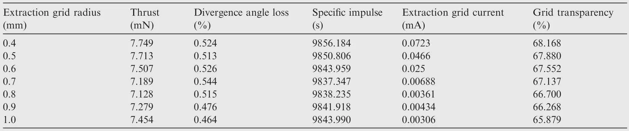
Table 3 Thruster performance parameters under different extraction grid apertures.

Table 4 Thruster performance parameters under different acceleration grid apertures.

Table 5 Thruster performance parameters under different extraction grid thicknesses.
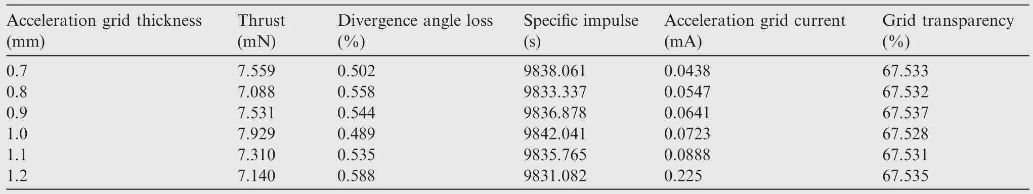
Table 6 Thruster performance parameters under different acceleration grid thicknesses.
4.2.4.Influence of grid spacing
The spacing between the screen grid and the extraction grid is designed according to the existing theory of the spacing between the screen grid and the acceleration grid in traditional grid system.20Since there is no mature theoretical design method for the extraction grid and acceleration grid spacing,it is necessary to judge the influence of the spacing on the grid performance through PIC simulation.
Based on the optimization of the grid aperture, the ion transport conditions with the grid spacing of 1.0, 1.2, and 1.4 mm are simulated, as shown in Fig.10 and Fig.11.
It can be seen from Fig.10 that at the distance of 1.0 mm,the ion density downstream of the acceleration grid hole is larger, and more charges are accumulated in the space, resulting in the potential on the axis behind the acceleration grid being greater than 0 V,which will cause the electrons in the space to return.More severely,it will cause the thruster to fail.With the increase of the grid spacing, the plasma density at the axis of the grid hole gradually decreases, and a potential less than 0 V appears on the axis of the grid hole,which can well inhibit the reflow of electrons and meet the performance requirements.However, as the spacing continues to increase, more ions will bombard the inner wall of the acceleration grid hole along the divergence angle, resulting in the corrosion of the grid hole gradually becoming more serious.With the overall consideration,the spacing between extraction and acceleration grids is selected to be 1.2 mm, which not only suppresses the electron reflow, but also reduces the impact of the grid life due to corrosion.
4.2.5.Influence of grid voltage
The extraction grid is a newly added grid in the DS3G thruster.There is no mature theory for its potential selection.By changing its potential value, the ion number distribution is calculated, as shown in Fig.12, and the performance parameters are calculated, as shown in Table 7.
Combining Fig.12 and Table 7, we can see that with the increase of the grid potential, the axis number density is slightly reduced, and the divergence angle is significantly reduced, thereby reducing the corrosion of the grid, but it affects the ion passage rate to a certain extent.Therefore,the extraction voltage is selected comprehensively as 4794 V.

Fig.10 Ion density distribution under different spacing between extraction and acceleration grids.

Fig.11 Potential distribution under different spacing between extraction and acceleration grids.

Fig.12 Ion number density distribution under different extraction grid voltages.

Table 7 Thruster performance parameters under different extraction grid voltages.
4.2.6.Optimization results
The performance parameters of the thruster before and after optimization are shown in Table 8.By optimizing the structure of the grid system, the divergence loss and maximum number density on the axis are almost half of the original, which improves focus performance, and the performance of specific impulse and thrust is also slightly improved, compared to the structure of University of Southampton.The specific impulse is 9877.24 s and the thrust is 7.28 mN, which is obtained under given working conditions.

Table 8 Comparison of performance parameters before and after optimization.
4.3.Limitation analysis of dual-stage grid system
The dual-stage grid system can realize the extraction and acceleration of the plasma under specific high-voltage conditions,so as to obtain higher performance.While the voltage condition of the traditional grid system is in the order of one thousand volts,it has not been reported whether the dual-stage grid system can be applied to low voltage conditions.In this section,the ion extraction of the double-stage grid system under different grid voltage conditions will be compared and analyzed,and its application scope will be studied.
Based on the optimized structure, different acceleration voltages are applied to the grid system to study the binding effect of the grid voltage on the ion beam,which also provides a reference for subsequent experimental research.Fig.13 shows the z-x 2D section of the ion number density distribution under different screen voltage conditions.The screen voltage is φsc=6294,5000,4000,3000,2000,1000 V respectively,and the extraction voltage is φext= 4794, 4000, 3000, 2000,1200, 700 V respectively.
It can be seen from Fig.13 that under high voltage conditions(φsc>3000 V),the ion beam distribution is good,and the grid system can work normally.However,under the condition of low voltage (φsc<2000 V), the ion beam is under-focused,and a large number of ions impact the surface of grid plate,which also reduces the insulation performance between the grids.Fig.14 shows the axis ion number density distribution curve under these six working conditions.With the reduction of the extraction voltage,the binding effect of the grid electric field on the ion current is weakened,and the ion density on the axis is significantly reduced.
The research shows that a set of dual-stage grid system structures cannot work normally under the condition of high voltage and low voltage at the same time, and cannot completely replace the traditional grid system.
4.4.Flexibility analysis for different propellants
The plasma distribution and grid extraction ability with different propellants are analyzed and compared for studying the flexibility of ion thruster.In the above simulation results, the propellant is Xe.However, Ar is usually used as a propellant in the laboratories, which is cheaper and thus more competitive in future engineering applications.Taking these two propellants as an example, the transport process of different kinds of particles is studied based on the optimized structural parameters.Fig.15 shows the ion number density distribution and axial velocity distribution of the two propellants under the same structural parameters.
After analysis and comparison, the following conclusions can be drawn:
(1) Under the same grid structure, voltage conditions and inlet parameters,changing the type of propellant has little effect on the focusing performance of the thruster,and the ion number density is basically unaffected.

Fig.13 Distribution of ion number density under different voltage conditions.

Fig.14 Axis ion number density distribution curve.

Fig.15 Plasma transport parameter distribution under different propellants.
(2) Since the ion mass becomes lighter, the speed obtained after absorbing the same potential energy as the Xe ion is higher,resulting in a larger increase in the specific impulse.In addition,the radial electric field also changes the speed of the ions greatly, so that more ions escape from the constraints of the grid system and impact the grid plate, affecting its lifetime.
Based on the above research, we can find that using different propellants under the same grid structure cannot achieve its optimal performance, and special designs for different propellants are required.
5.Conclusions
Based on the PIC/MCC algorithm, this paper simulates the transport process of plasma in the grid system of a dualstage grid ion thruster using a three-dimensional parallel simulation program.The grid aperture is uniformly opened in a region with a radius of 2.5 cm in the center of the grid plate.According to the symmetry of the grid aperture structure,only 1/4 grid aperture is taken as the computational domain.The ions are treated as particles, and the electrons are treated as fluids, which obey the Boltzmann distribution.It can be seen from the simulation results that the 3D simulation program can effectively simulate the plasma flow field distribution.Under the initial calculation conditions, the ion beam current collimation is acceptable,but the density at the axis is too high.By optimizing the structure of the grid system, the phenomenon of beam current being unreasonable is improved,and the performance of specific impulse and thrust is improved slightly.The specific impulse under the given working conditions is 9877.24 s and the thrust is 7.28 mN.
Based on the optimized grid structure parameters,the influence of different voltage conditions on the extraction performance of the dual-stage grid system is studied.The simulation results show that the grid system has certain limitations.Under the condition of high voltage (φsc>3000 V), the grid system can work normally.However, under low voltage conditions (φsc<2000 V), the ion beam is under-focused and ions cannot be extracted normally.Therefore,during the operation of the dual-stage grid system, a high voltage condition should be maintained.
In addition,by changing the propellant,the grid system can still extract and accelerate the ions normally.However,due to the different ion masses, the radial confinement of the ions becomes worse and affects the life of the grid.Therefore,when the propellant is changed,the grid structure and the discharge state need to be optimized and improved, so that the thruster can work effectively for a long time.
Declaration of Competing Interest
The authors declare that they have no known competing financial interests or personal relationships that could have appeared to influence the work reported in this paper.
Acknowledgements
This study was co-supported by the National Key R&D Program for Intergovernmental International Scientific and Technological Innovation Cooperation, China (No.2021YFE0116000), the National Natural Science Foundation of China (Nos.12175032, 12102082 and 12275044), the National Natural Science Foundation of China and the Belarusian Republican Foundation for Fundamental Research(No.12211530449), the Fundamental Research Funds for the Central Universities of China(No.DUT22QN232), ,the S&T Program of Hebei, China (Nos.YCYZ202201 and 216Z1901G), the S&T Innovation Program of Hebei, China(Nos.SJMYF2022X18 and SJMYF2022X06), the Science and Technology Project of Hebei Education Department,China (No.ZC2023144), and S&T Program of Langfang,China (No.2022011039).
杂志排行

CHINESE JOURNAL OF AERONAUTICS的其它文章
- Improving surface integrity when drilling CFRPs and Ti-6Al-4V using sustainable lubricated liquid carbon dioxide
- A hybrid chemical modification strategy for monocrystalline silicon micro-grinding:Experimental investigation and synergistic mechanism
- Analysis of grinding mechanics and improved grinding force model based on randomized grain geometric characteristics
- Experimental and modeling study of surface topography generation considering tool-workpiece vibration in high-precision turning
- Collaborative force and shape control for large composite fuselage panels assembly
- Ultrasonic constitutive model and its application in ultrasonic vibration-assisted milling Ti3Al intermetallics