Improving surface integrity when drilling CFRPs and Ti-6Al-4V using sustainable lubricated liquid carbon dioxide
2023-09-05igoRODRIGUEZPedroJosARRAZOLAMikelCUESTALukSTERLEFrnciPUAVEC
Iñigo RODRIGUEZ, Pedro José ARRAZOLA, Mikel CUESTA,Luk STERLE, Frnci PUŠAVEC
a Faculty of Engineering, Mondragon Unibertsitatea, Arrasate-Mondragon 20500, Spain
b Faculty of Mechanical Engineering, University of Ljubljana, Ljubljana 1000, Slovenia
KEYWORDS Carbon fibers;Cryogenics;Green manufacturing;Machining;Solid lubricants;Surface morphology;Titanium alloys
Abstract In the quest for decreasing fuel consumption and resulting gas emissions in the aeronautic sector,lightweight materials such as Carbon Fiber Reinforced Polymers(CFRPs)and Ti-6Al-4V alloys are being used.These materials, with excellent weight-to-strength ratios, are widely used for structural applications in aircraft manufacturing.To date, several studies have been published showing that the use of metalworking fluids(MWFs),special tool geometries,or advanced machining techniques is required to ensure a surface quality that meets aerospace component standards.Conventional MWFs pose a number of environmental and worker health hazards and also degrade the mechanical properties of CFRPs due to water absorption in the composite.Therefore, a transition to more environmentally friendly cooling/lubrication techniques that prevent moisture problems in the composite is needed.This research shows that lubricated LCO2 is a viable option to improve the quality of drilled CFRP and titanium aerospace components compared to dry machining,while maintaining clean work areas.The results show that the best combination of tool geometry and cooling conditions for machining both materials is drilling with Brad point drills and lubricated LCO2.Drilling under these conditions resulted in a 90 % improvement in fiber pullout volume compared to dry machined CFRP holes.In addition, a 33 % reduction in burr height and a 15%improvement in surface roughness were observed compared to dry drilling of titanium.
1.Introduction
Material development in aeronautics is driven by weight reduction, since the fuel consumption can be reduced by decreasing take-off weight.1The reduction in fuel consumption has been on a continuous upward trend in recent years,mainly for cost saving reasons.An additional motivation for this trend is the 50 % carbon dioxide (CO2) and 80 % nitrogen oxide (NOx)reduction specified in the aeronautical research goals by the Advisory Council of Aeronautical Research in Europe(ACARE).2
Titanium alloys such as Ti-6Al-4V and fiber reinforced materials like carbon fiber reinforced polymers (CFRPs) are also gaining traction due to their excellent weight-to-strength ratio.In addition,composites offer the possibility of manufacturing more complex, aerodynamic and/or easy to assemble fuselage components.1,3
At present, the aeronautical industry is developing hybrid composite/metal stacks to enhance the properties of newgeneration structures.4To enable easy disassembly for repairs and maintenance CFRP and Ti-6Al-4V layers are joined by rivets are inserted into holes drilled through both materials.Due to the complexity of the parts to be machined and the large number of holes required, drilling operations are preferred to create the boreholes.5The individual layers are stacked and then drilled in a single shot,to minimize positional errors.6However,the disparate characteristics of each material in the stack make drilling in a single shot challenging.
CFRP and Ti-6Al-4V present very different chip formation mechanisms, and thus have dissimilar machinability and surface integrity problems.For instance, Ti-6Al-4V is an alloy with high strength and low thermal conductivity.Cutting temperatures can range from 500 °C to 1000 °C when varying the cutting speed from 25 m/min to 75 m/min, as Li and Shih7proved when drilling a 13 mm thick Ti-6Al-4V plate with a 10 mm diameter drill in dry conditions.This creates several tool wear problems for drilling tools, namely non-uniform flank wear, chipping and cracking.8Built-up-Edge (BUE)and diffusion problems appear when drilling titanium alloys owing to the high chemical reactivity of the workpiece with the tool material, which is further promoted by the high cutting temperatures.9On the other hand, various simultaneous failure modes are involved in the chip formation mechanism of CFPRs, which are predominantly governed by the angle between the fiber orientation and the cutting direction (fiber orientation angle).10In drilling, the fiber orientation angle changes constantly as the tool rotates,therefore,different chip formation mechanisms occur simultaneously.In addition, the abrasive dust-like chips of the reinforcement fibers create abrasive wear, promoting a smooth and uniform rounding pattern along the entire cutting edge.1,5
When drilling CFRP/Ti-6Al-4V stacks,the tool is subjected to strong forces, cutting temperature fluctuation and vibrations.This is because the thermal/mechanical responses when drilling each material of the stack are different, therefore the interface of the materials becomes a very challenging zone to machine.4Abrasive and adhesive wear mechanisms occur simultaneously when drilling stacks, and the combined effect promotes faster tool wear than machining the materials separately.This was demonstrated by Alonso et al.5
Burr formation and poor surface roughness are the greatest surface integrity concerns for titanium alloys.The height of the burr that is created at the exit of the tool is greater with increased cutting speed.This may be an indicator of the plastic deformation caused by thermal softening occurring in the cutting process,as Gao et al.stated.11On the other hand,surface roughness is mainly affected by an increase in feed rate.Poor surface roughness can lead to microcracking,making the components less resistant to fatigue and susceptible to early fracture.12
In the case of drilling CFRPs, the main surface integrity issues are fiber pull-out and delamination.The former occurs when bundles of carbon fibers are pulled away by fiber matrix debonding and matrix stripping, and they are more likely to occur in fiber orientation angles near 125° and 315° due to the chip formation mechanisms happening at those angles, as stated by Eneyew and Ramulu.13Delamination is a form of damage that is likely to occur in the interlaminar region between adjacent layers in laminate parts.Several techniques for evaluating delamination are described in the literature,but the adjusted delamination factor(Fda)proposed by Davim et al.14is the most employed,as it takes into account the effect of the areal damage and thin cracks in the delamination.
Delamination is classified as either ‘‘peel-up”or ‘‘pushout”.Peel-up delamination occurs at the entry of the drill,and it is caused when there is incomplete fracture of the fibers at the entrance.Then, the upper layers of the composite are lifted as the helix of the tool pulls up them up (similar to the action of a corkscrew).15Delamination at the exit (or pushout delamination) is considered more severe than peel-up delamination.This form of surface defect occurs when the drilling tool applies a pushing force to the last plies of the laminate before exiting the plate.When the thrust force is greater than the bond strength between the layers the composite laminates separate and delamination occurs.
When drilling these aeronautical materials in a stack,different surface integrity problems arise depending on the stacking order.In a CFRP to Ti-6Al-4V configuration the titanium chip evacuation becomes more complicated resulting in a scratched CFRP surface by the titanium chips.The Ti-6Al-4V plate placed underneath the CFRP prevents major push-out delamination problems, however spalling can occur, when the titanium chips enlarge the hole at the bottom part of the CFRP plate when being evacuated.4In a Ti-6Al-4V to CFRP configuration delamination problems are present as the composite material is not supported.In addition,due to the high temperature reached by the drill after machining the titanium phase,carbonization of the epoxy matrix can occur, usually showing up as a discolored ring in the CFRP plate surface.
In Fig.1, a graphical representation of the most common surface integrity problems and tool wear mechanisms occurring when drilling CFRP and Ti-6Al-4V aeronautical materials is shown.The tool wear SEM images are adapted from16for CFRP and8for Ti-6Al-4V, while the defects in CFRP were summarized by Gao et al.15.The chip deposition and scratched surface defect images were observed by Pecat and Brinksmeier,17and the matrix carbonization was reported by Hussein et al.18
Several research works have analyzed the feasibility of new techniques to improve the machinability and surface integrity when drilling these two materials.These studies focused on optimized advanced cutting techniques such as orbital drilling(also known as helical milling)6or vibration assisted drilling,11,18,19that improve the machining process by enhancing chip evacuation.Also, specially designed tool geometries have been tested,to reduce thrust force in CFRPs and improve chip breakability in Ti-6Al-4V.These tool geometries are shown in Fig.2..3

Fig.1 Tool wear mechanisms and surface integrity problems present when drilling CFRP and Ti-6Al-4V aeronautical materials either separately or in stacked configuration using different stacking orders.

Fig.2 Geometrical features of different drill bits employed in aeronautical manufacturing 3.
Reducing cutting temperatures, minimizing friction between tool and workpiece, and improving chip evacuation are also crucial aspects to increase tool life and decrease machinability and surface integrity problems, therefore metalworking fluids (MWFs) are usually employed to process difficult-to-cut materials.20However, they present hazards for the environment as well as for workers,21in addition to degrading the interlaminar strength of composite materials such as CFRPs, due to moisture absorption.22Turner et al.23analyzed the influence of different MWFs on the mechanical properties of CFRPs and showed that water and oil based coolants caused swelling on the composite due to water absorption.This in turn decreased the mechanical strength of the specimens tested.
Minimum Quantity Lubrication (MQL) employs highly localized lubrication via oil atomization, to minimize the amount of lubricant (≤500 mL/h) while ensuring friction reduction in the tool-chip interface.24However, MQL does not provide cooling, which can be critical when machining materials with low thermal conductivity like titanium.Additionally, for CFRP/Ti-6Al-4V stack drilling, Xu et al.24demonstrated that the use of MQL improves surface morphology but does not reduce delamination damage.
Sub-zero cooling employs liquified gases like liquid nitrogen (LN2) and liquid carbon dioxide (LCO2) as coolants.These fluids cool the cutting zone and eliminate pollution at the workplace, since the gases scape to the atmosphere during after phase change.However, their heat extraction mechanisms are very different.LN2is sprayed to the cutting zone at -196 °C and extracts the heat form the cutting zone due to evaporation of the liquid phase.LCO2on the other hand,is stored at room temperature and 57 bar of pressure.When the liquid is expulsed to ambient pressure, a drop in temperature (down to -78.5 °C) is achieved after a sudden expansion due to Joule-Thomson effect.This creates a two-phase flow where dry ice and gaseous CO2coexist, and the temperature reduction is achieved by the sublimation of the solid phase.25Giasin et al.26achieved a 47 % improvement on the surface roughness of drilled GLARE fiber metal laminates for aerospace structural applications,by applying LN2and MQL cooling.Moreover,Rodriguez et al.27declared LCO2cooling to be a feasible technique to improve hole accuracy and tool life when drilling CFRP/Ti-6Al-4V stacks.
Pereira et al.,28revealed that LCO2causes less ozone depletion and respiratory effects than LN2during the liquified gas production process.In addition to this, and unlike LN2,LCO2can be kept in liquid state at room temperature, which opens the possibility of delivering it through the tool and mixing it with lubricants such as MQL oils and solid lubricants.29Different types of LCO2+ MQL application devices have been employed for diverse machining operations,ranging from external nozzles that combine the LCO2and oil just before the delivery, to concentric nozzles in order in order to provide LCO2and MQL separately through the tool.25However, the pressure difference between the LCO2(57 bar) and MQL(10 bar), makes the combination of cooling and lubricant media difficult.25For this reason, GrguraŠet al.,30proposed a novel LCO2assisted machining concept based on a single channel, where the lubricant media and LCO2are premixed and delivered as a homogeneous media to the cutting zone.This concept is operable with any lubricant in any state, such as oil or solid lubricants.Recent advances in LCO2+ MQL supplying methods are depicted in Fig.3(a).
Solid lubricating particles can be found in different geometrical shapes (spherical or non-dimensional, linear or onedimensional, and stratiform or two-dimensional), and their lubricating and heat evacuating properties are dependent on it (Fig.3(b)).2-D nanoparticles (MoS2, graphite, boric acid,etc.), present the greatest lubricating and heat evacuating properties among all shapes due to their layered structure.31Graphite is the nanoparticle that exhibits the best lubricating and heat dissipating properties.However, MoS2has been shown to have very good lubricity in oxygen deficient atmospheres and at low temperatures, making it the most suitable lubricating nanoparticle to use in combination with LCO2.32Additionally, MoS2is listed as a non-hazardous substance,and its 2-D nanostructures are used for biomedical applications.33Therefore, it should not pose more health risks than MQL oils, but it can help to reduce the friction coefficient,as demonstrated by PuŠavec et al.29
After thorough reviews, it was concluded that delivering pre-mixed LCO2and lubrication is a technique with potential for drilling aeronautical components.This environmentally friendly cooling technique ensures clean working spaces and produces less pollution during liquification than other subzero fluids like LN2.34Additionally, LCO2opens the possibility of delivering combined cooling and lubricant media, and pre-mixing both fluids prior to delivering them through a single channel increases the penetration of the lubricant into the cutting zone.30
To the best of the authors’knowledge, no study has been conducted comparing different environmentally friendly cooling/lubrication methods based on LCO2for drilling of CFRP and Ti-6Al-4V.In addition, there are few studies in the literature concerning LCO2+MQL cooling when drilling aeronautical materials,and research about LCO2+MoS2cooling for general drilling operations is rarely found.
In this study the performance of different tool geometries is analyzed under dry,LCO2,LCO2+MQL and LCO2+MoS2cooling/lubrication.CFRP and Ti-6Al-4V materials are tested separately to eliminate the uncertainties that occur in the hybrid stack configuration interface, and minimize the effects of combined tool wear.The influence of different tool geometries and cooling conditions on machining performance was evaluated by measuring cutting forces.To assess the quality of the machined holes, delamination and fiber pull-out were observed in the CFRP phase, while surface roughness, burr height and microstructural damage were measured for the Ti-6Al-4V phase.The main novelty of this study is the experimental demonstration of the feasibility of single channel cooling/lubrication based on LCO2, to improve the surface integrity of drilled CFRP and Ti-6Al-4V aeronautical components.
2.Tools, materials and experimental set-up

Fig.3 Advances in lubricated LCO2 cooling/lubrication technologies.

Table 1 Geometrical characterization of different tool geometries.
Three different cutting tool geometries were employed, with one drill bit designed specifically for CFRPs, one for Ti-6Al-4V alloys, and another for the CFRP/Ti-6Al-4V stacks(Table 1).Each of the tools has a geometry designed for optimally cutting different materials.For instance, Brad point tools have a centering point and two peripheral cutting edges forming a 180°point angle.These side cutters reduce the thrust force and the delamination when drilling composites,while still cutting titanium alloys efficiently due to a 140° point in the center.Double point angle tools reduce thrust force with a small point angle in the first stage of the tool.These tools improve chip breakability due to a change in the direction of chip flow promoted by the double cutting edges.The OSG A-SUS 3D is a conventional twist drill with a 140°point angle,designed for drilling titanium alloys.The large point angle leads to the cutting lips engaging earlier with the material,thus beginning the cutting action sooner.This helps to reduce burr formation.
The cutting edge of the tools was characterized using an Alicona Infinite Focus SL optical 3D microscope with ×10magnification.Each cutting edge radius was measured three times,and the average value was calculated.The measurement zones for each cutting edge are specified in Table 1, and each cutting edge of the double point angle tool is separated by different color profiles.Although each of the presented tools have geometries optimized to machine one specific material, studies have shown their suitability for machining both CFRPs and Ti-6Al-4V when the appropriate machining parameters are used.1

Table 2 Mechanical properties of reinforcement fibers and epoxy matrix of aeronautical grade CFRP composite at room temperature.
Aeronautical grade reinforcement fibers and epoxy matrix were employed to fabricate the CFRP plates.Both the Ti-6Al-4V and CFRP plates had the same dimensions(175 m × 250 m × 5 mm).The mechanical properties of the CFRP plates are summarized in Table 2, and those of the Ti-6Al-4V in Table 3.The CFRP plates were fabricated in a Resin Transfer Molding (RTM) press using 20 layers of reinforcement per plate.A compressive force of 5 Tn was exertedon a mold at 140 °C for 180 minutes to cure the epoxy resin.Subsequently, a post-curing treatment was carried out in an oven at 180 °C for 2 h.

Table 3 Chemical composition (wt%) and mechanical properties of Ti-6Al-4V alloy at room temperature.

Fig.4 Employed experimental set-up: (a) General overview of the CNC machining center and Arclub One LCO2 system; (b)Detailed view of the set-up; (c) Detail of the tool, coolant supply line and dynamometer; (d) Detail of the workpiece clamping system with the aluminum support plate.
The machining tests were carried out on a Doosan NX 6500 II CNC machining center.The sustainable cooling media for drilling the CFRP and Ti-6Al-4V plates was supplied externally with using the Arclub One LCO2system, as shown in Fig.4(a) and (b).This sub-zero cooling system can supply CO2in liquid phase to the cutting zone and additionally combine lubricant media, expulsing the mixture through a single channel, as reported by GrguraŠet al.30The lubricant media is pressurized to 60 bar before combining it with the LCO2to ensure a homogeneous dissolution.The MQL oil used was Rhenus Lub SSB neat oil as it showed great solubility with LCO2.30The physical and chemical properties are given in Table 4.
When using solid particle lubrication, a suspension of isopropyl alcohol (IPA) and MoS2was premixed in a separate chamber at a weight percentage of 5 % before being pressurized and combined with the LCO2, as seen in Fig.5.IPA was employed to prepare the lubricating solid particle suspension since it evaporates at room temperature,leaving only solid particles in the machining area.The LCO2was supplied at a temperature of -78.5 °C and a mass flow rate of 0.2 kg/min,while the flow rates for the lubricant media were 100 mL/h for MQL and 40 mL/h for MoS2, in accordance with PuŠavec et al.29These flow rates for the lubricant come also into agreement with those employed in other research studies where LCO2+ MQL cooling and lubrication was used.35
Thrust force and torque values were measured using a Promicron Spike wireless dynamometer (Fig.4(c)).Cooling media was supplied through an external 0.8 mm nozzle at an angle of 45°,and at a distance of 3 mm from the tip of the cutting tool.The tested plates were clamped onto a support plate which had holes 50 % larger than the diameter of the drill(Fig.4(d)).The support plate was employed to reduce the unpredictability in fiber delamination brought about by the deflection of the workpiece when drilling in different positions of the plate 15.In addition, the holes were accurately positioned to ensure that the drilling operation occurred at the points where the fibers of the CFRP twill fabric intersected,thereby reducing the uncertainties in the experiments.

Table 4 Physical and chemical properties of LCO2 and MQL oil.
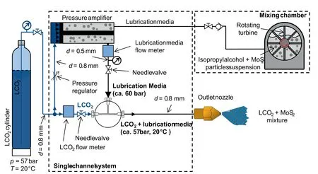
Fig.5 Delivery of LCO2 and isopropyl alcohol + MoS2 solid particles suspension through a single channel (adapted from GrguraŠet al.30).
3.Research methodology
The three tools presented in Table 1 were tested on the CFRP and Ti-6Al-4V plates employing four different cooling conditions: Dry drilling, LCO2assisted drilling, LCO2+ MQL assisted drilling, and LCO2+ MoS2(solid particles) assisted drilling.All tool geometries and cooling conditions were tested separately under the same machining parameters.It well is known that for drilling hard and brittle materials like CFRP,high cutting speeds and low feed rates are required, while for titanium alloys such as Ti-6Al-4V low cutting speeds are preferred to reduce tool wear.3However, in the present work the same machining parameters were selected for both materials, despite the fact that the CFRP and Ti-6Al-4V plates were machined separately.This was done to simulate the conditions of drilling CFRP/Ti-6Al-4V without experiencing the increase in tool wear generated by the machining of the interface between both materials.
The machining parameters were chosen from the literature on drilling CFRP/Ti-6Al-4V stacks.36,37Although,the selected cutting speed for drilling Ti-6Al-4V is considered to be high,these conditions were chosen to test the efficiency of the cooling/lubrication systems at high material removal rates, and in the knowledge that lower cutting speeds could generate surface integrity problems in the CFRP plate 3.The testing inputs are detailed in Fig.6(a).Tool geometry and cooling techniques were defined as variable parameters and every combination possible was tested in both CFRP and Ti-6Al-4V materials.Every testing condition was repeated three times to check the repeatability of the experiments.
Thrust force(Fz)and torque(Mz)cutting force components were monitored when drilling both CFRP and Ti-6Al-4V plates using a Promicron Spike wireless dynamometer (Fig.6(b)).The signals were acquired with a 1 kHz sampling frequency and the noise was cleaned using a Savitzky Golay filter.This filter fits consecutive sets of neighboring data with;in this case, a third-degree polynomial.The sample frame selected was 201 data points.
3.1.Surface integrity evaluation in the CFRP phase

Fig.6 Overview of research methodology.
A range of surface integrity parameters were analyzed to evaluate the quality of the drilled hole (Fig.6(b)).Peel-up (hole entry) and push-out (hole exit) delamination were evaluated for holes drilled in the CFRP plates using a Keyence VHX 6000 digital microscope, with a 100x magnification.The surface topography parameters measured to evaluate the fiber pull-out in the CFRP were analyzed using an Alicona infinite Focus SL optical 3D microscope, with a ×10 magnification.To evaluate the drilling induced delamination in CFRP plates the one-dimensional delamination factor (Fd) is usually calculated by dividing the diameter of the hole (DNOM) with the diameter of the circle which inscribes the maximum delamination damage (DMAX).1This is expressed as Eqn 1:
However, this evaluation technique does not consider long thin cracks which greatly affect the integrity of the CFRP plate.Therefore, Davim et al.14proposed an adjusted delamination factor (Fda) which takes into account the contribution of uniform areal damage and thin cracks to delamination, as depicted in Fig.7(a).This method was employed to evaluate the peel-up delamination at the entry (Fig.11(a)), and the push-out delamination at the exit(Fig.11(b)).Fdais expressed as seen in Eq.(2), where AMAXand ANOMare expressed as given in Eqs.(3) and (4), subsequently:
For assessing the amount of pulled-out fibers in the surface of the drilled borehole two parameters were evaluated: the peak material volume (Vmp) and the arithmetical mean height of the surface (Sa).The peak material volume is calculated from several profiles contained inside the analyzed area and indicates the volume of the highest 20 % points of the profile,as seen in Fig.7(b).Therefore, the higher this number the greater the amount of fibers that peak above the surface of the drilled borehole.Additionally, Sawas measured because the surface of the CFRP borehole was too irregular to be evaluated by measuring Ra.Sais the extension of Raand it expresses the different in height of each point of a surface compared to the arithmetical mean of it.
3.2.Surface integrity evaluation in the Ti-6Al-4V phase
In the case of the Ti-6Al-4V plates,burr height and the surface texture parameters affecting the fatigue strength of a metal were analyzed in each hole (Fig.6(b)).As explained by Arola and Williams38the surface texture parameters that define the fatigue strength are Ra(average deviation in surface height from the profile mean line),Rt(maximum peak to valley height of roughness profile), and Rz(mean peak to valley height of roughness profile).
On the other hand, the criterion selected for evaluating the burr height was the ten point height of the selected area(S10z).Burr morphology may be irregular in some cases and measuring devices might measure outlying points that can alter the results.As Kacalak et al.39demonstrated, the ten-point height(S10z) parameter is less susceptible to minor or particular changes, thus it is appropriate to evaluate the overall burr height without taking into account singular defects.
Both surface roughness and burr height are critical surface integrity parameters for the aeronautical industry, since low fatigue strength can lead to microcracks,and an excessive burr height can cause bolted unions to become loose.40Additionally,a microstructural analysis of the Ti-6Al-4V holes has been carried out in order to observe the damage generated by different tool geometries.The samples were polished and chemically etched before being analyzed using a Leica DM i8C microscope with a ×50 magnification.
4.Results and discussion
4.1.Cutting forces
Fig.8 shows the thrust force and torque results for the SECO Brad Point,SECO Double point and OSG A-SUS 3D drill bits under dry,LCO2,LCO2+MQL and LCO2+MoS2assisted drilling conditions.Fig.8 (a) and (c) refer to the CFRP plate,and Fig.8(b) and (d) to the Ti-6Al-4V.As can be observed,similar trends appear for thrust force and torque in both materials for each tool-cooling condition couple.
The lowest thrust force values were obtained in dry drilling conditions, as the cooling effect of LCO2cooled down the workpiece material increasing its flow stress.Nevertheless,the addition of lubricants smoothened the increase in cutting forces, and in particular the torque component.This effect was particularly noticeable when employing MoS2.The results go along with the findings by PuŠavec et al.,29who demonstrated that LCO2does not provide lubrication, but significantly lower friction coefficients are obtained with LCO2+ MQL and LCO2+ MoS2.
Tool geometry also affected the cutting forces.The reduction in thrust force brought about acute point angles can be observed, as the SECO Double Point tool yielded the lowest thrust force values when drilling CFRP.On the other hand,the torque generated by these geometries is generally higher than conventional twist drills due to the greater cutting edge length, as double point angle tools have two cutting edges.41A more acute point angle and a longer cutting edge generate a smaller chip thickness for the same feed per tooth value.This may have increased the torque generated by the SECO Double Point tool when drilling Ti-6Al-4V, which lead to a catastrophic failure of the tool.
Such tool failure happened after a single drilled hole both in dry and LCO2+ MoS2cooling conditions, as illustrated in Fig.9.Analysis of the surface of the drilled borehole and the force signal revealed that the tool failed during the cutting operation.This is indicated by the yellow arrow in Fig.9(c),where the graph showing the cutting force signal corresponds to the time the drill was cutting through the workpiece.Tool wear and borehole damage were observed using a Keyence VHX 6000 digital microscope with a ×100 magnification.
The most likely wear mechanism that led to the failure of the SECO Double Point tool was adhesion.Similar tool wear was reported by Cantero et al.9and Alonso et al.,5as they

Fig.9 Comparison of tool wear of SECO Double point drill bit when drilling CFRP and Ti-6Al-4V plates.
The specific cutting force (Kc) was calculated by dividing the experimentally measured torque by the radial distance from the center of the cut cross-section.Fig.10 shows that the best results are yielded by the SECO Brad point tool, as this tool geometry achieved the lowest torque values from all the tools tested.As expected, the addition of lubricant media lowered the specific cutting force as the torque is also reduced.
The specific cutting force values obtained under dry cutting conditions were in good agreement with the results obtained by other researchers.43,44Nevertheless, even when lubricants were used, the specific cutting force when drilling Ti-6Al-4V was higher than the values obtained by Rahim et al.43,44when using flood coolant(1500 N/mm2).When using emulsion cooling the enhanced chip evacuation may prevent chip clogging at the flutes of the tool reducing torque and Kc.When applying found that high cutting speed conditions and a long cutting edge length can lead to an increase in cutting temperature.This in turn promotes formation of solid solution of titanium in the carbide, and therefore adhesion between the tool and workpiece.After observing that the tool failed even when applying LCO2+MoS2cooling and lubrication it was determined that the geometry of the SECO Double Point tool was not suitable for drilling Ti-6Al-4V under the employed machining parameters, and it was decided not to continue the testing with such geometry for drilling titanium alloys.
The SECO Brad Point drill geometry yielded lower thrust force values than OSG A-SUS 3D when drilling CFRP plates(Fig.8(a)), but higher values when drilling Ti-6Al-4V plates(Fig.8(b)).The low thrust force results obtained by the SECO Brad Point drill bit on the CFRP plates may be due to a reduction in the extrusion effect.Similar results were also observed by Xu et al.42when drilling CFRP.In their study,they showed that Brad point drills produced lower cutting forces compared to conventional twist drills, which they attributed to the fact that the peripheral cutting edges of the Brad point geometry helped to increase the shear of the material,and thus minimize drilling forces.
On the other hand, it is believed that the peripheral cutters increased the deformation of the material and resulted in a higher thrust force when drilling Ti-6Al-4V, as seen in Fig.8(b).It is also worth noting that the shearing promoted by the peripheral cutting edges of the Brad point drill helped to reduce the torque when drilling both materials.MQL, even if the cutting zone is lubricated, the chip evacuation is poor since the volumetric flow of the oil is very little.Therefore, the specific cutting force values for LCO2+ MQL cooling are similar to those for dry drilling.

Fig.10 Specific cutting force(Kc)values for drilling experiments with different tool geometries under different cooling conditions.

Fig.11 Surface integrity evaluation when drilling CFRP with different tool geometries under different cooling conditions.
4.2.Surface integrity
The effect of different tool geometries and cooling/lubrication techniques on surface integrity parameters were analyzed(Fig.6(b)).For CFRP plates peel-up and push-out delamination, and fiber pull-out were evaluated, while different surface roughness parameters, burr height and microstructural damage were observed for Ti-6Al-4V plates.
4.2.1.Surface integrity of CFRP plates
As illustrated in Fig.11(a) and (b), the best delamination results were obtained when drilling CFRP with the SECO Double Point drill bit.This tool also generated the smallest thrust force values of all three drill bits,regardless of the cooling medium,proving the relationship between thrust force and delamination observed by other authors.10,45It can be observed that the use LCO2cooling increases push-out delamination as thrust force values also increase, and adding lubricating media to the LCO2reduces the debonded plies of CFRP at the exit of the hole.There was almost no difference in delamination results obtained by the Brad point drills and the OSG A-SUS 3D conventional twist drills (Fig.11(a) and(b)) however, the SECO Brad point tools obtained a drilled borehole with less pulled out fibers (Fig.11(c) and (d)).

Fig.12 Comparison of delaminated areas and drilled CFRP borehole cross sections obtained with different tool geometries under different cooling conditions.
Higher thrust force values were measured when using LCO2+ MQL or LCO2+ MoS2, compared to dry drilling(Fig.8).Nevertheless,lower delamination damage was observed with lubricated LCO2.This could be because the addition of LCO2+lubricant to the cutting zone kept the tool colder and achieve a cleaner cut.Similar results were observed by Ge et al.,6who reported a smoother surface with smaller delamination due to an increase in resin strength and fiber brittleness by the cryogenic coolant.This lower temperature and cleaner cutting of the CFRP composite helped the epoxy matrix to maintain its mechanical properties and prevented the sliding of the carbon fiber plies,thus reducing the drilling induced delamination.
In Fig.11(c) and (d) the peak material volume (Vmp) and arithmetical mean height (Sa) of the CFRP drilled boreholes are depicted.These surface parameters were analyzed to obtain information about the volume of pulled-out fibers on the machined surface.Fiber pull-out is greatly affected by the fiber orientation angle,13and for this reason in the present study all the cross sections were cut at the same orientation to eliminate uncertainties.

Fig.13 Surface integrity evaluation when drilling Ti-6Al-4V with different tool geometries under different cooling conditions.
The SECO double point angle tool obtained the least amount of pulled-out fibers.The double cutting edge of this tool promotes a change in the chip flow direction, which in turn improves chip breakability.The authors believe that the improved chip breaking ability helped to reduce the fiber pull-out in the boreholes.Adding lubricant media substantially improved the surface finish of the drilled borehole, especially for the Brad point tool, achieving results similar to or better than the double point angle tools.
Overall, Fig.11 shows that the effect of LCO2mainly affects the delamination due to an increase in thrust force.This increase in delamination weakens the interlaminar bond between layers, and results in greater fiber pull-out.The addition of lubricants has very little effect on delamination,as it is mainly influenced by thrust force.Nevertheless, lubrication greatly improved the quality of the machined surfaces.Similar results were obtained by Xu et al.,24who found a strong improvements in surface morphology and little to no effect on delamination when drilling CFRP with MQL lubrication.
In Fig.12 the quality of the drilled CFRP holes obtained with different tool geometries and cooling/lubrication methods can be observed.The SECO double point drill bit achieved the least delamination and the best borehole surface finish.However, holes with similar quality are obtained when employing the SECO Brad point tool under LCO2+MQL and LCO2+-MoS2cooling conditions.The OSG A-SUS 3D tool yielded the holes with the largest volume of pulled-out fibers.In the holes drilled with this tool the epoxy matrix exhibits several voids,as well as significant delaminated carbon fiber plies at the exit of the hole.It can also be observed how an increase in delamination leads to a raise in the amount of pulled out fibers,mainly at the exit of the hole.
The reduction in delamination and fiber pull-out is clearly seen when adding lubricant media to the LCO2.For SECO Brad Point and SECO Double Point tool geometries, the surface of the borehole presents very little defects,and both pushout and peel-up delamination are reduced compared to dry or LCO2cooling conditions.
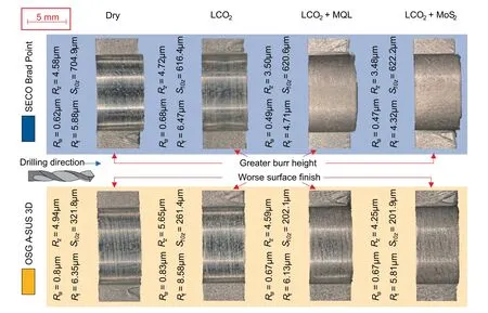
Fig.14 Comparison of burr height and drilled Ti-6Al-4V borehole cross sections obtained with different tool geometries under different cooling conditions.
4.2.2.Surface integrity of Ti-6Al-4V plates
Fig.13(a) to (c) sets out values of various surface roughness parameters yielded by the different tool geometries under different cooling conditions.The holes drilled with the SECO Brad point drill bit had a smoother surface compared to those drilled with the OSG A-SUS 3D.This improvement in surface roughness might be caused by the peripheral cutting edges present in the Brad point drill bit.It can also be noted that the addition of lubricant media like MQL or MoS2to the LCO2resulted in improved surface roughness.The surface roughness trends are in line with the torque measurements when drilling the Ti-6Al-4V plates (Fig.8(d)), and demonstrate the effect of the generated torque on the surface finish of the drilled hole.
On the other hand, Fig.13(d) shows that a significantly lower burr height was obtained when employing the OSG ASUS 3D drill bit, which is specifically designed for drilling Ti-6Al-4V alloys.The higher burr generated by the SECO Brad Point drill bit is likely caused by the 180° point angle of the tool.
The addition of LCO2decreased the burr height from that of dry drilling.This was expected, as the cooling effect of the LCO2reduced the plastic deformation occurring at the exit of the plate.Adding lubricant media further reduced the height of the burr, as the MQL and MoS2decreased the generated torque lowering the cutting temperature.Similar trends were observed by Xu et al.24who reported a significant reduction in burr height when drilling CFRP/Ti-6Al-4V stacks with MQL,in comparison to dry cutting.The relationship between increase in temperature and burr height was also observed by Gao et al.,11who found that the increase in cutting temperature caused by greater cutting speeds resulted in larger exit burrs.
For visual comparison images of the boreholes obtained with OSG A-SUS 3D and SECO Brad Point drill under different cooling/lubrication conditions are shown in Fig.14.As can be seen, smaller burrs were obtained with the conventional twist drill bit.The 140° point angle that this tool has might have helped to reduce the burr height due to a more progressive cut at the exit of the Ti-6Al-4V plate in comparison to the SECO Brad Point drill bit, which has a 180° point angle.It can also be observed how the addition of lubricant media such as MQL or MoS2to the LCO2helps to improve the roughness of the machined surface.
When analyzing the microstructure of drilled Ti-6Al-4V boreholes,it can be observed that the Brad point drill achieved to machine the holes with the least damage.In Fig.15, the most relevant damage features present in the entry and the exit planes of the titanium plates drilled with different tools are shown.It must be noted that the holes drilled with the SECO Double Point presented on the analysis are the ones where the tool failed, shown in Fig.9.As it can be seen Brad point drill bits generate a minimal amount of surface drag compared to the OSG A-SUS 3D drill bits, which achieved lower burr height but greater surface roughness, surface drag and even a small amount of white layer.

Fig.15 Comparison of microstructure of Ti-6Al-4V boreholes obtained with different tool geometries under dry cutting.

Fig.16 Chemical composition analysis of WC inclusion in Ti-6Al-4V workpiece after drilling with SECO double point angle tool.
As Fig.15 depicts the holes drilled with the SECO Double Point drill bit present a greater depth of white layer, surface drag and re-deposited layer.When observing the microstructure of the boreholes produces by the Double Point drill bit,inclusions were detected (Fig.16(a)).The chemical composition of such inclusions was analyzed using a Scanning Electron Microscope (SEM).It was found that WC was present in the Ti-6Al-4V workpiece,as shown in Fig.16(b).These inclusions of the tool material in the Ti-6Al-4V could be due to brittle fracture of the tool.
5.Conclusions
In the presented research work the effect of different drill bit geometries and a range of environmentally friendly ‘‘subzero”cooling/lubrication techniques was analyzed, when drilling CFRP and Ti-6Al-4V aeronautical materials.The principal findings are as follows:
(1) The application of lubricated LCO2with MQL or MoS2in the cutting zone helped to improve the resulting surface integrity of drilled CFRP and Ti-6Al-4V workpieces, regardless of the tool geometry.These findings could be extended to other machining areas where conventional MWFs cannot be used.
(2) The SECO Brad point drill bit proved to be the best tool for machining CFRP and Ti-6Al-4V aeronautical materials.When drilling CFRP plates with this tool and lubricated LCO2, similar surface quality to the one generated by specialized composite drill bits was achieved.Regarding Ti-6Al-4V drilling,the SECO Brad point tool obtained superior surface roughness and substantially less microstructural damage than tools designed for drilling titanium.One drawback however, was that the peripheral cutting edges of this tool produced a larger burr height at the exit side of the Ti-6Al-4V plate in comparison to conventional twist drill geometries, like OSG A-SUS 3D.
(3) The most optimal cooling condition was LCO2+MoS2.Overall,employing the SECO Brad point drill bit under LCO2+ MoS2cooling/lubrication resulted in a 90 %improvement in the fiber pull-out volume compared to dry machined CFRP holes.In addition, a 33 % burr height reduction, and a 15 % improvement in surface roughness were observed,when compared to dry drilling Ti-6Al-4V.
(4) The‘‘sub-zero”temperature of the CO2dry ice projected onto the cutting zone caused an increase in the hardness of the workpiece material, which was found to be undesirable for every tool-material couple.Cutting forces were higher when employing LCO2cooling in comparison to dry cutting, however they decreased to values similar to dry machining when adding lubrication.The lubricants might have helped overcome the hardening effect caused by the addition of LCO2.Solid lubricants were found to be the lubricating media that performed best, slightly ahead of MQL oils.
(5) The SECO Double point angle drill bit failed to machine titanium alloys.The acute point angle and long cutting edges of the double point tool generated a smaller chip thickness than the other two tool geometries, which increased cutting forces and torque.The increase in torque might have contributed to the adhesion of the tool to the workpiece material, which led to tool failure due to chipping after a single hole in dry cutting and even under LCO2+ MoS2cooling/lubrication conditions.Since the tool was unable to machine Ti-6Al-4V despite using cooling and lubrication, it was concluded that the SECO Double Point geometry was not suitable for drilling titanium alloys at the selected machining parameters.
(6) The improvement of surface integrity without using conventional MWFs favors the reduction of costs due to waste management and cleaning of the chemical additives in the cutting fluid.Eliminating this postmachining cleaning operations helps to decrease the environmental impact of the manufacturing process.
Declaration of Competing Interest
The authors declare that they have no known competing financial interests or personal relationships that could have appeared to influence the work reported in this paper.
Acknowledgements
This research was financially supported by CRYOMACH Project (INNO-20182049), and by the ARRS – national science agency within research program 2-0266(Advance manufacturing technologies for high quality and sustainable production/Napredne izdelovalne tehnologije za visoko kakovostno in trajnostno proizvodnjo).
杂志排行

CHINESE JOURNAL OF AERONAUTICS的其它文章
- A hybrid chemical modification strategy for monocrystalline silicon micro-grinding:Experimental investigation and synergistic mechanism
- Analysis of grinding mechanics and improved grinding force model based on randomized grain geometric characteristics
- Experimental and modeling study of surface topography generation considering tool-workpiece vibration in high-precision turning
- Collaborative force and shape control for large composite fuselage panels assembly
- Ultrasonic constitutive model and its application in ultrasonic vibration-assisted milling Ti3Al intermetallics
- Developing a novel radial ultrasonic vibration-assisted grinding device and evaluating its performance in machining PTMCs