Collaborative force and shape control for large composite fuselage panels assembly
2023-09-05ZhnghoWANGDongshengLILihengSHENYiSUIYunongZHAI
Zhngho WANG, Dongsheng LI,b, Liheng SHEN, Yi SUI,Yunong ZHAI,b,*
a School of Mechanical Engineering and Automation, Beihang University, Beijing 100191, China
b Ningbo Institute of Technology, Beihang University, Ningbo 315832, China
c COMAC Shanghai Aircraft Manufacturing Co., Ltd, Shanghai 201324, China
KEYWORDS Assembly;Collaborative force and shape control;Composite panel;Hexapod parallel robots;Method of influence coefficients
Abstract This study proposed a force and shape collaborative control method that combined method of influence coefficients (MIC) and the elitist nondominated sorting genetic algorithm(NSGA-II) to reduce the shape deviation caused by manufacturing errors, gravity deformation,and fixturing errors and improve the shape accuracy of the assembled large composite fuselage panel.This study used a multi-point flexible assembly system driven by hexapod parallel robots.The proposed method simultaneously considers the shape deviation and assembly load of the panel.First,a multi-point flexible assembly system driven by hexapod parallel robots was introduced,with the relevant variables defined in the control process.In addition, the corresponding mathematical model was constructed.Subsequently, MIC was used to establish the prediction models between the displacements of actuators and displacements of panel shape control points,deformation loads applied by the actuators.Following the modeling,the shape deviation of the panel and the assembly load were used as the optimization objectives, and the displacements of actuators were optimized using NSGA-II.Finally, a typical composite fuselage panel case study was considered to demonstrate the effectiveness of the proposed method.
1.Introduction
The fuselage panel is an important aerodynamic bearing part of the aircraft, whose shape accuracy directly affects the flight aerodynamic performance.Considering their high strength-toweight ratios, high stiff-ness-to-weight ratios, excellent resistance to fatigue and corrosion,and unique mechanical property designability, composites are being increasingly used in the new generation of large airliner structures.1For instance, the fuselages of B787, A350XWB, and CR929 all use large composite panels.2,3The composite fuselage panel has a large size,a low rigidity,and a low geometric manufacturing accuracy.During the assembly process, its low manufacturing accuracy is coupled with fixturing errors, gravity deformation,and other factors, often resulting in the shape deviation of the panel from the allowable accuracy range of the process.Subsequently, the aerodynamic shape of the entire aircraft is destroyed, thus affecting the final quality of the aircraft product.Therefore, in the actual assembly process, the shape deviation of the composite fuselage panel must be corrected to achieve qualified shape accuracy.
In the digital assembly process of modern aircraft, the shapes of fuselage panels are usually corrected through multipoint flexible tooling, mainly consisting of multiple numerical control actuators.These actuators complete the positioning of the workpiece by forming an envelope surface of the workpiece in space.Subsequently, they deform the workpiece to a certain extent through the active movement of each actuator to correct its shape deviation.In recent years, several studies have focused on this assembly shape correction tooling.Schwake and Wulfsberg4and Fette et al.5fixed the single-axis vacuum cups on the conformal frame at the end of the industrial robot and corrected the shape of the composite panel through the single degree of freedom (DOF) movement of the vacuum cups.Simultaneously, a force sensor was integrated at the end of the vacuum cup to monitor the assembly force borne by the panel in real time.To solve the problem of large assembly gap between the fuselage barrel sections of the B787 widebody airliner, Hunt and Hussain6and Wen et al.7evenly arranged 10 jack actuators integrated with force sensors in the lower half of the composite fuselage barrel section to correct its shape.Zhang et al.8corrected the shape of the composite wing panel by installing a screw compression mechanism equipped with a force sensor on the assembly tooling.However,the single-DOF shape correction tooling proposed in these studies can only correct the radial assembly deformation of the panel, which has limited shape-correcting ability.In addition, it causes pulling during the shape correction process,which can easily damage the panel.Bi et al.9developed an assembly tooling based on a three-axis actuator,which corrected the shape of the metal panel through the 3-DOF translational movement of the actuator.However, the tooling was not equipped with force sensors and cannot monitor the assembly force borne by the panel.Composite panels are brittle and readily damaged when subjected to forces; therefore, the tooling cannot be directly used for the assembly deformation correction of composite panels.Arista and Falgarone10developed a flexible tooling for A350XWB rear fuselage assembly, which used a three-axis linear actuator integrated with a force sensor to correct the shape of composite panels.Such shape correction tooling based on three-axis actuators only has a 3-DOF translational drive and 3-DOF force sensing capabilities,and the capabilities of shape control and assembly load sensing are not sufficient.Schmitt et al.11and Bertelsmeier et al.12used a serial robot integrated with 6-DOF-force-torque sensors to correct the shape deviation of composite panels.Ramirez and Wollnack13developed a shape correction tooling for composite panels assembly based on hexapod parallel robots.Compared with the shape correction tooling based on three-axis actuators,this robot-driven flexible assembly tooling can achieve 6-DOF fully active movement and real-time monitoring of the 6-DOF assembly force,with stronger shape control and assembly load sensing abilities.As the actual assembly shape accuracy of composite fuselage panels must be controlled within±0.6–0.8 mm,serial robots generally suffer from problems of large deflection and low positioning accuracy, while parallel robots are more suitable for the shape correction of composite panels owing to their high positioning accuracy.Therefore, in this study, a multi-point flexible assembly system driven by hexapod parallel robots was established to correct the shape deviation of the large composite fuselage panel.
After the shape correction tooling is determined, the shape accuracy of the composite panel and its force bearing during the assembly process must be controlled.Thus,an appropriate control strategy must be adopted to determine the optimal driving amount of each actuator.In the literature about control strategies, Schmitt et al.11,14,15established a mathematical model between the shape deviation of composite panels and the assembly force exerted by the actuators based on the equivalent stiffness matrix.Bi et al.9established a mathematical model between the position errors of measurement points of the metal panel and the displacements of actuators based on the partial least squares regression method (PLSR).Similarly,Fang et al.16also used PLSR to establish a mathematical model between the position errors of measurement points of fuselage and the contact force increments of positioners forcecontrol axes.Thereafter, Schmitt et al., Bi et al.9and Fang et al.conducted online control of the shape of workpieces according to the shape deviation measured.The main idea of this online control strategy is to establish a mathematical model between the shape deviation of the workpiece, that is independent variable, and the driving amounts of actuators, that are dependent variables;and the shape deviation of the workpiece is iteratively corrected based on the model.However,in the actual assembly process, many factors must be considered, including more than one objective function, which renders the description of the function relationship between them and the independent variables through a single model challenging.Therefore, some scholars adopted an optimization control strategy.In contrast to the online control strategy, the main idea of this optimization control strategy is to establish mathematical models between the driving amounts of actuators,that are independent variables, and the objective functions to be controlled(such as workpiece shape deviation),that are dependent variables.Further, the driving amounts of actuators are optimized based on the model.This control strategy can establish multiple mathematical models for multiple objective functions, ensuring the control effectiveness of workpiece shape considering many factors.Based on the assumption of small component displacements and linear elasticity, Arista et al.10adopted simplified stiffness matrixes to build mathematical models between the displacements of actuators and the shape deviation of key points of the composite fuselage panel,the force bearing by contact points of the actuator.Subsequently,they optimized the actuator displacements based on the models.However, the simplified stiffness matrixes are calculated based on the nominal model, which has a large deviation from the actual model, and the model accuracy needs to be improved.Yue et al.17established a mathematical model between actuators’forces and dimensional deviations of the barrel section of the composite fuselage with an improved stochastic Kriging model and then optimized actuators’forces with the interior point method based on the model.Lee et al.18proposed a neural network Gaussian process model to describe the function relationship between actuators’forces and dimensional deviations of the composite fuselage.Zhong et al.19directly loaded the system equation from the finite element model to establish a mathematical model between the locations and forces of actuators and the shape deviation of composite fuselage,and then used cvx software to solve the optimal location and force of each actuator based on this model.The methods17–19used a force control strategy to maintain the maximum force constraints, so as to ensure the safety requirements during the fuselage assembly process.However, in the multi-point flexible assembly system driven by hexapod parallel robots built in this study, the controller inside the robot is based on displacement.If the force control strategy is used,an external feedback control loop must be added to the robot controller, which results in a problem of control accuracy.Thus, previously proposed control strategies9-11,14–19cannot be directly applied to the shape control problem of composite fuselage panel assembly in this study,thus necessitating the development of a new control method.
Based on the multi-point flexible assembly system driven by hexapod parallel robots,this study proposed an assembly force and shape collaborative control method combining method of influence coefficients(MIC)and the elitist nondominated sorting genetic algorithm (NSGA-II).The method considers both the shape deviation and assembly load of the panel.In this study, MIC was used to build the prediction models between the displacements of actuators and displacements of panel shape control points, deformation loads applied by the actuators.Then this paper considered the shape deviation of the composite fuselage panel and the assembly load as the optimization objectives and optimized the driving amounts of actuators using NSGA-II.
The remainder of this paper is organized as follows.In Section 2,the multi-point flexible assembly system driven by hexapod parallel robots is introduced, and the relevant variables are defined in the control process.In Section 3,the mathematical model of force and shape collaborative control for the large composite fuselage panel assembly is established.In Section 4, the modeling process based on MIC is introduced.In Section 5, a flowchart of the proposed method is presented.In Section 6, a typical composite fuselage panel is presented to verify the method, followed by an analysis and discussion of the case study results.The conclusion is then presented in Section 7.
2.Multi-point flexible assembly system driven by hexapod parallel robots
2.1.System composition
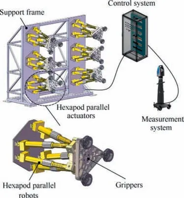
Fig.1 Schematic of multi-point flexible assembly system driven by hexapod parallel robots.
In this paper,a multi-point flexible assembly system driven by hexapod parallel robots was used to correct the shape deviation of the large composite fuselage panel.As shown in Fig.1, the flexible assembly system mainly comprised a support frame, multiple groups of hexapod parallel actuators, a measurement system,and a control system.Each group of hexapod parallel actuator included: a hexapod parallel robot, a gripper, and a high-accuracy 6-DOF-force-torque sensor.The hexapod parallel robot drove the gripper through translation and rotation in three orthogonal directions of its X,Y,and Z axes to realize the shape control of the panel.Further, the gripper was mounted at the end of the actuator with 3 vacuum cups, forming an equilateral triangle structure.The cup was designed with a mechanical stop,which can stably fix composite panels with different curvatures and constrain their shapes.In addition, a 6-DOF-force-torque sensor was installed between the gripper and the actuator, which can monitor the force and torque in the three directions of X,Y, and Z axes in real-time.This type of actuator is capable of 6-DOF fully active drive, which has high structural rigidity, high transmission accuracy, strong shape control ability,and assembly load sensing ability.
The measurement system adopts a laser tracker and the corresponding target balls to construct a panel coordinate system and measure the shape information of the panel during the shape correction process.The control system was used to control the movement of multiple actuators and connected with 6-DOF-force-torque sensors to monitor the deformation loads applied by the actuators in real-time.
2.2.Definition of the relevant variables
To characterize the shape deviation of the panel, this study first constructed the panel coordinate system with point O1as the coordinate origin, direction O1O2as the X axis, and the inner normal of the plane O1O3O4as the Z axis.Thereafter,nine shape control points were set on the panel(as shown in Fig.2),and the shape deviation of the panel was characterized by the position deviations of shape control points in the panel coordinate system, which were measured by means of the laser tracker.
In addition, as shown in Fig.3, this study established the TCP coordinate system at the end of each actuator.The origin of the TCP coordinate system is the central point of the triangle gripper.Here,the X direction is along the panel axial direction, Y direction is along the panel circumferential direction,and Z direction is along the panel inner normal direction.In this study, the displacements of actuators and the applied deformation loads were measured based on the corresponding TCP coordinate system.This paper characterized the assembly load of the panel by the deformation load applied by each actuator.
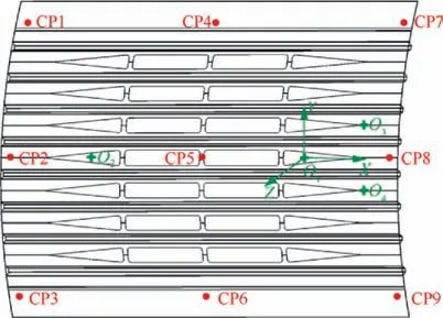
Fig.2 Panel coordinate system and shape control points.
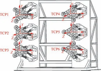
Fig.3 TCP coordinate systems.
3.Mathematical model of assembly force and shape collaborative control
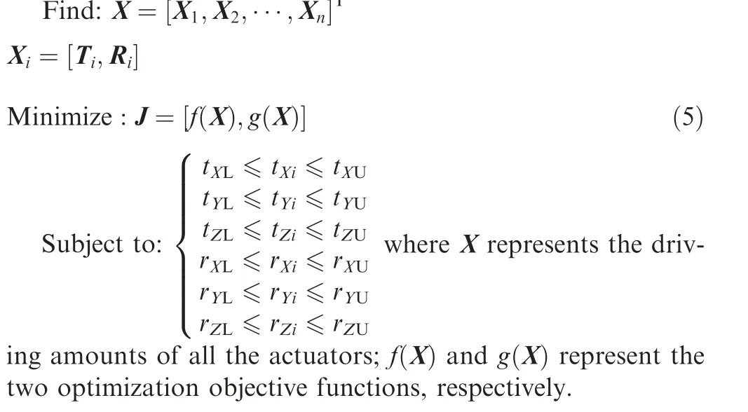
In this study, by controlling the displacements of actuators, a certain elastic deformation was caused to the composite panel,thereby reducing its shape deviation.To realize a more effective correction of the shape deviation of the panel without damaging it, the displacement of each actuator should be reasonably controlled.Therefore, the displacement Xiof each actuator was considered as the design variable, which is expressed as follows:
where Tirepresents the translational driving amounts of the ith actuator, Rirepresents the rotational driving amounts of the ith actuator, and n represents the number of actuators.
Comprehensively considering the movement ranges of hexapod parallel actuators and the possible damage to the composite panel during the shape correction process, Xishould satisfy the following constraint conditions:
where tXL,tYL,and tZLand tXU,tYU,and tZUrepresent the lower and upper boundaries of the translational driving amounts of actuators in the X-, Y- and Z-directions, respectively; rXL,rYL,and rZLand rXU,rYU,and rZUrepresent the lower and upper boundaries of the rotational driving amounts of actuators in the X-, Y- and Z-directions, respectively.
Based on the requirements of controlling the shape accuracy and stress of the composite fuselage panel, this study considered the shape deviation f (X )of the composite fuselage panel and the assembly load g X( )it bears as the optimization objectives, which is expressed as follows:
where Ycrepresents the initial position vector of panel shape control points, which is measured online by the laser tracker;Y^(X )represents the displacement vector of shape control points during the shape correction process; Y*represents the theoretical position vector of shape control points; W is the weight diagonal matrix, whose diagonal elements reflect the relative importance of corresponding position deviations of shape control points.
where F(X )represents the deformation loads applied by the actuators during the shape correction process, which is measured by 6-DOF-force-torque sensors;V is the weight diagonal matrix,whose diagonal elements reflect the relative importance of corresponding deformation loads applied by the actuators.
Thus, force and shape collaborative control for the large composite fuselage panel assembly is a multi-design variable,multi-objective continuous optimization problem.The mathematical model of this problem can be expressed as:
4.Method of influence coefficients
Method of influence coefficients (MIC) is a modeling method based on the assumption of small displacements and a linear material model, and it constructs the response model using a unit disturbance method.It offers the advantages of small calculation amount, few samples required, and simple operation.20–22As the shape deviation of the composite fuselage panel during the assembly process is a small displacement,and the assembly deformation is elastic deformation,this study used MIC to establish the prediction models between the displacements of actuators and displacements of panel shape control points, deformation loads applied by the actuators,respectively.
Assuming that the composite fuselage panel has m shape control points, and each shape control point has 3-DOF for displacement, the displacement vector of shape control points has 3m dimensions.This study used n hexapod parallel actuators to correct the shape deviation;thus,the displacement vector of actuators has 6n dimensions.

where Y^represents the displacement vector of all shape control points;X represents the displacements of all the actuators;K is the coefficient matrix between them.

where F represents the deformation load vector applied by the actuators; S is the coefficient matrix between X and F.
5.Proposed method
Based on the multi-point flexible assembly system driven by hexapod parallel robots,this study proposed a force and shape collaborative control method for large composite fuselage panels assembly combining MIC and NSGA-II.In the control process, both the shape deviation and assembly load of the panel were considered.The proposed method is mainly classified into two stages.In the first stage, the training and testing samples were generated through the design of experiments(DOE)and physical experiments.Subsequently,the prediction models between the displacements of actuators and displacements of panel shape control points, deformation loads applied by the actuators were established using MIC, and the prediction accuracies of the two models were tested through the testing samples.
In the second stage,the two prediction models were embedded into the artificial intelligence multi-objective optimization algorithm to search for the optimal driving amounts of actuators.First,the initial positions of panel shape control points of the panel were obtained through the measurement system,which were compared with the theoretical positions to obtain the position deviations of shape control points.Then, the shape deviation of the panel and the assembly load it bears were used as the objective functions, and the multi-objective optimization of the displacements of actuators was performed.NSGA-II runs fast, has a strong global search capability, and maintains a high population diversity in the final Pareto optimal solution set, which is widely used in various engineering optimization problems.23,24Therefore, this study adopted NSGA-II to optimize the displacements of actuators.The flowchart of the method is shown in Fig.4.
6.Case study
To verify the above optimization method, this study built a multi-point flexible assembly system driven by hexapod parallel robots and performed an assembly force and shape collaborative control experiment based on a typical composite fuselage panel.
6.1.Design of experiments
As shown in Figs.2 and 5, the dimensions of the composite fuselage panel component are 3100 mm × 2041 mm, and the radius of curvature is 2960 mm.It is formed by co-curing the skin and stringers.The skin is designed with variable thickness along the circumferential direction in the range of 2.22–3.885 mm.Further, the layup information is: middle [45/-45/-45/90/45/0/0/45/90/-45/-45/45], a total of 12 layers; two ends[45/-45/45/90/-45/-45/90/0/45/0/0/0/45/0/90/-45/-45/90/45/-45/45],a total of 21 layers.The thickness of stringers is 1.665 mm,and the layup information is [45/90/90/-45/0/-45/90/90/45], a total of 9 layers.Both the skin and stringers are made of carbon fiber reinforced epoxy resin composite material T800/X850 with a density of 1570 kg/m3.The mechanical properties of the material are listed in Table 1.The laser tracker used in this study is a Leica AT960MR with an angular measurement range of ± 360°in the horizontal direction and ± 145°in the vertical direction, a maximum measurement radius of 20 m and a measurement accuracy of 15 μm + 6 μm/m.
As shown in Figs.1 and 6,this study adopted six actuators to correct the shape deviation of the composite fuselage panel.Each actuator had six active displacement DOFs, tXi, tYi, tZi,rXi, rYiand rZi.As the spatial pose of the panel must maintain fixed during the shape correction process, active and passive actuators needed to be reasonably selected.The active actuator corrected the shape deviation of the panel through its own active movement,whereas the passive actuator remained stationary to ensure that the spatial pose of the panel was fixed.This study compared the difference in the shape control capabilities of the following three schemes through finite element analysis:

Fig.4 Flowchart of the proposed method.

Fig.5 Composite fuselage panel.
(1)The top two actuators TCP1 and TCP4 are used as passive actuators, the remaining actuators, TCP2, TCP3, TCP5,and TCP6 are used as active actuators;
(2) The middle two actuators TCP2 and TCP5 are used as passive actuators, the remaining actuators, TCP1, TCP3,TCP4, and TCP6 are used as active actuators;
(3) The bottom two actuators TCP3 and TCP6 are used as passive actuators, the remaining actuators, TCP1, TCP2,TCP4, and TCP5 are used as active actuators.

Table 1 Mechanical properties of T800/X850.
The results showed that the weighted square summation of the displacements of panel shape control points of scheme (2)was greater when the same driving amounts of actuators was applied, while the assembly load was smaller.Therefore, this study selected the middle two actuators TCP2 and TCP5 as the passive actuators, the remaining actuators, TCP1, TCP3,TCP4, and TCP6 were used as active actuators.

Fig.6 Actual multi-point flexible assembly system driven by hexapod parallel robots.

Table 2 Mean prediction errors of displacements of panel shape control points.
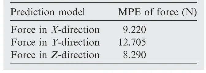
Table 3 Mean prediction errors of force applied by actuators.

Table 4 Mean prediction errors of torque applied by the actuators.
As the displacement of actuators along the direction rZihad minimal effect on the shape correction of the panel, and can easily cause structural instability, the displacement DOF of each active actuator in the direction of rZiwas ignored.Limited by the size of the composite fuselage panel,after it was fixed by the three rows of actuators,the circumferential distance between the middle actuator and the upper or lower actuator was already very small; in addition, the panel is reinforced by the stringer, resulting in large axial stiffness.Therefore, the movement ranges of actuators in the directions tXiand tYiwere small.During the physical experiment, with the increase in tXiand tYi, the vacuum cups slipped; thus, the displacement DOFs of each active actuator in the directions tXiand tYiwere ignored.
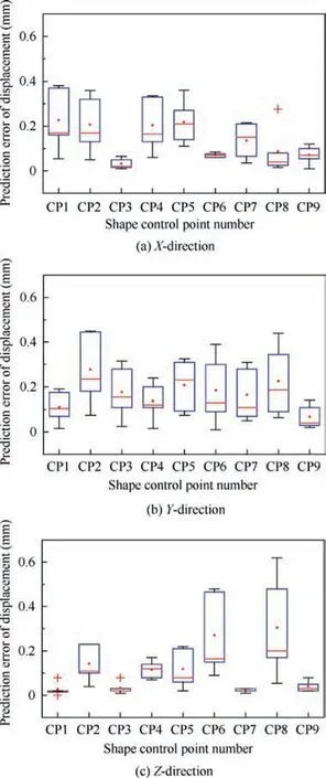
Fig.7 Prediction errors of displacements of panel shape control points in X-, Y- and Z-directions.
In conclusion, four active actuators were used in this case,and each actuator retained three active displacement DOFs,tZi, rXi, and rYi.Therefore, the design variable X in this case had a total of 12 elements.In this case, the sampling plan was designed based on MIC, and 12 and 5 groups of samples were used for training and testing, respectively.The design tables of the training and testing samples are shown in the Appendix A.Subsequently, the physical experiments according to the designed sampling plan were performed to obtain the objective function values at each sample point.
6.2.Modeling and prediction results of MIC
Based on the modeling strategy of MIC proposed in Section 4,this study established the prediction models between the displacements of actuators and displacements of panel shape control points, deformation loads applied by the actuators using the MATLABTMplatform.The independent variable of the two models are the displacements X12×1of all active actuators,and the specific form is expressed as
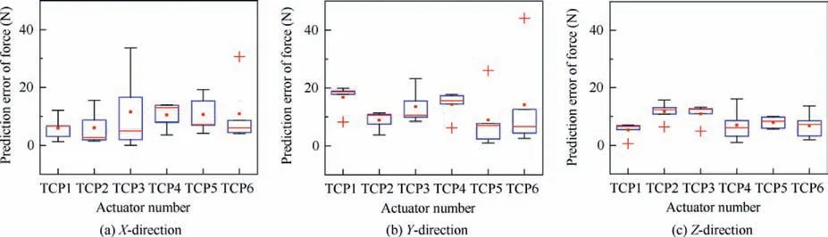
Fig.8 Prediction errors of force applied by actuators in X-, Y- and Z-directions.
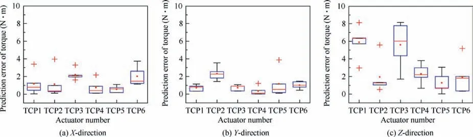
Fig.9 Prediction errors of torque applied by actuators in X-, Y- and Z-directions.

Fig.10 Pareto optimal solutions.
where x3i-2,x3i-1,x3i(i=1,2,3,4)represents the displacements of the ith active actuator in the directions tZi,rXi, and rYi.The dependent variables are the displacements Y^27×1of all the panel shape control points and the deformation loads F36×1applied by all the actuators.The specific form is as follows:
where ^y3l-2, ^y3l-1, ^y3l(i=1,2,∙∙∙,9) epresents the displacement of the lth hape control point in the X-, Y- and Z-directions.
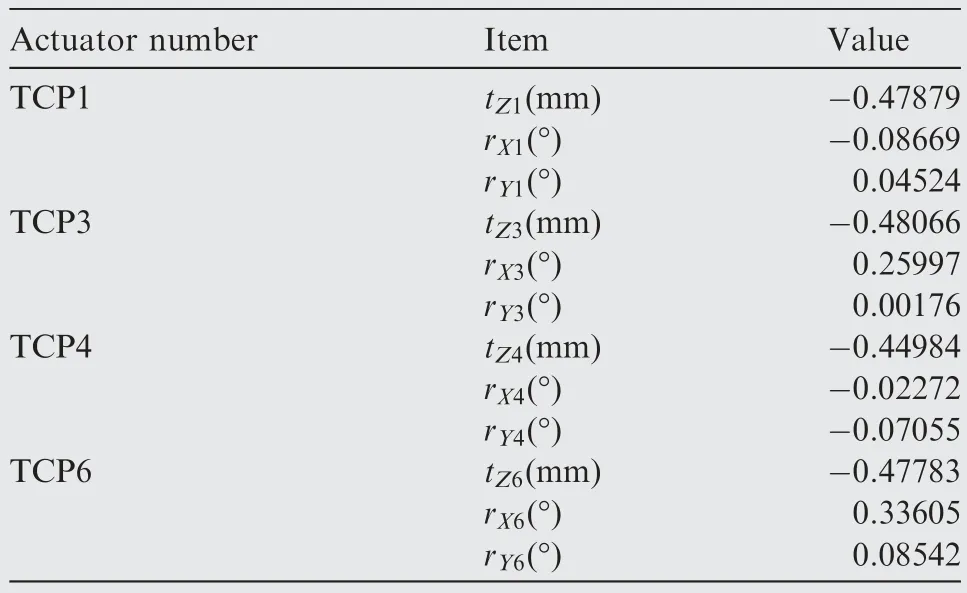
Table 5 Optimization results of displacements of actuators.
where f6i-5, f6i-4, f6i-3(i=1,2,∙∙∙,6) represents the force applied by the ith actuator in the X-, Y- and Z-directions; f6i-2,f6i-1, f6irepresents the torque applied by the ith actuator in the X-, Y- and Z-directions.The coefficient matrices K27×12and S36×12of the two prediction models are shown in the Appendix A.
After establishing the prediction models, the prediction accuracies of the two models are tested based on the testing samples.Table 2 lists the mean prediction errors (MPE) of the displacements of panel control points in the X-, Y- and Zdirections.The MPE of the force applied by the actuators in the X-, Y- and Z-directions is listed in Table 3, and that of the torque is listed in Table 4.The corresponding boxplots are shown in Figs.7, 8, and 9, respectively.
The testing results showed that the MPE of the singledirection displacements of panel shape control points was controlled within the range of 0.2 mm, the MPE of the singledirection force applied by the actuators was controlled within the range of 13 N,and the MPE of the single-direction torque was controlled within the range of 4 N∙m.Owing to the influence of the movement error of actuators and the measurement error of 6-DOF-force-torque sensors during the shape correction process, the two models exhibited certain prediction errors.However, compared with the assembly shape accuracy requirement of ± 1.5 mm, the allowable assembly force requirement of approximately 300 N and the allowable assembly torque requirement of approximately 60 N∙m, the prediction accuracies of the two models were acceptable.
6.3.Force and shape collaborative control results
In this section,NSGA-II was applied to the established prediction models, and the displacements of active actuators were optimized to reduce the shape deviation of the panel and the assembly load it bears.In addition, to prevent the vacuum cup from slipping or the movement error of actuators from being too large,combined with the single-direction movement experiment of actuators, this case set the upper and lower boundaries of the driving amounts of actuators in the three active displacement DOFs, tZi, rXi, and rYi, as follows:

The crossover and mutation probabilities of NSGA-II were set to be 0.8 and 0.2,respectively;the population size was set to be 100;the maximum number of iterations was set to be 15000;the fitness function tolerance was set to 1exp(-100); and the fraction of individuals on the Pareto front was set to be 0.3.The optimized Pareto front is shown in Fig.10.
Comprehensively considering the shape deviation of the panel and the assembly load it bears, this case selected the solution marked with a red five-pointed star in Fig.10 as the optimal solution.And the displacements of active actuators are listed in Table 5.
To verify the shape correction effect of the solution,the displacement load shown in Table 5 was applied in this case.After the shape correction, the position deviations of panel shape control points and the deformation loads applied by the actuators were measured.Fig.11 shows the position deviations of panel shape control points before and after the correction.It can be seen that, compared with the Y- and Zdirections, the position deviations of shape control points in the X-direction was smaller,that was because the panel was reinforced by the stringer along the X-direction, resulting in a high rigidity.Further, the single-direction position deviations of panel shape control points after the correction were controlled within the accuracy range of ± 0.6–0.8 mm.For the shape control points CP6 and CP9 with the excessive deviations, a certain residual deviation was observed owing to the limit of the movement ranges of actuators; however, the total residual deviation was significantly reduced.Thus, based on the above analysis, the method proposed in this study exhibited good effectiveness for the shape deviation control of the large composite fuselage panel.
For further comparative analysis, based on the prediction models established in Section 6.2, the position deviations of panel shape control points after the correction and the deformation loads applied by the actuators were calculated and compared with the measured values, whose results are listed in the Appendix A, separately.It is evident that the predicted values are consistent with the experimental values.In addition,the absolute value of the single-direction force applied by actuators after the correction did not exceed 80 N, and that of the single-direction torque did not exceed 25 N∙m.These values are within the engineering specifications of the assembly requirement of COMAC Shanghai Aircraft Manufacturing Co., ltd.Thus, this method effectively controls the level of assembly load borne by the panel.

Fig.11 Position deviations of panel shape control points in the X-, Y- and Z-directions before and after the correction.
7.Conclusion
Based on the multi-point flexible assembly system driven by hexapod parallel robots,this study proposed a force and shape collaborative control method for large composite fuselage panels assembly combining MIC with NSGA-II.The method considers both the shape deviation and assembly load of the panel.And a typical composite fuselage panel was considered a case to demonstrate the effectiveness of the proposed method.The main conclusions are as follows:
1.Based on MIC,this study established the prediction models between the displacements of actuators and displacements of panel shape control points, deformation loads applied by the actuators.The testing results showed that the models exhibited good prediction accuracies.
2.This study considered the shape deviation of the panel and the assembly load it bears as the optimization objectives,used NSGA-II to perform multi-objective optimization on the displacements of actuators, and obtained an optimal driving amounts of actuators that simultaneously satisfied the requirements of assembly shape accuracy and assembly load of the panel.Finally, the effectiveness of the method was verified through the physical experiment.
3.Owing to the influence of the movement error of actuators,the panel manufacturing error, the measurement error of the assembly load,and other factors in the actual assembly process, the relationships between the displacements of actuators and displacements of panel shape control points,deformation loads applied by the actuators are not completely linear.Therefore, a nonlinear surrogate modeling method that considers various uncertainties can be developed in the future to further improve the accuracies of the prediction models.4.This paper adopted NSGA-II to search the optimal driving amounts of actuators.The next research can be to compare NSGA-II with other multi-objective optimization algorithms such as multi-objective particle swarm algorithm in optimization efficiency when solving such multi-design variable,multiobjective continuous engineering optimization problem,so as to find more suitable algorithm and further improve the effectiveness of force and shape collaborative control.
Declaration of Competing Interest
The authors declare that they have no known competing financial interests or personal relationships that could have appeared to influence the work reported in this paper.
Acknowledgements
This work was supported by National Natural Science Foundation of China (No.52105502), Fund of National Engineering and Research Center for Commercial Aircraft Manufacturing (Nos.COMAC-SFGS-2019-263 and COMAC-SFGS-2019-3731), and the Fundamental Research Funds for the Central Universities (No.3042021601).
Appendix A.(See Tables A1–A6).
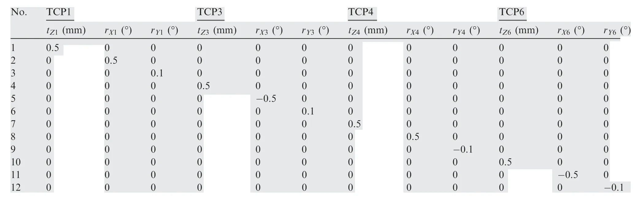
Table A1 Design table of the training samples.
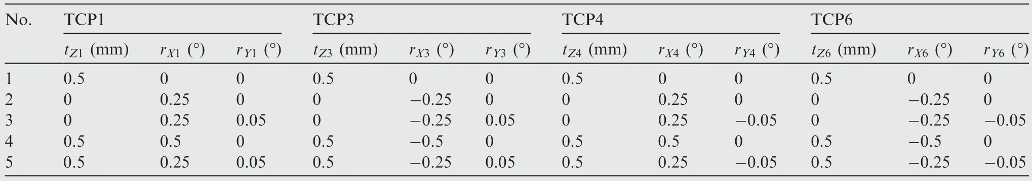
Table A2 Design table of the testing samples.
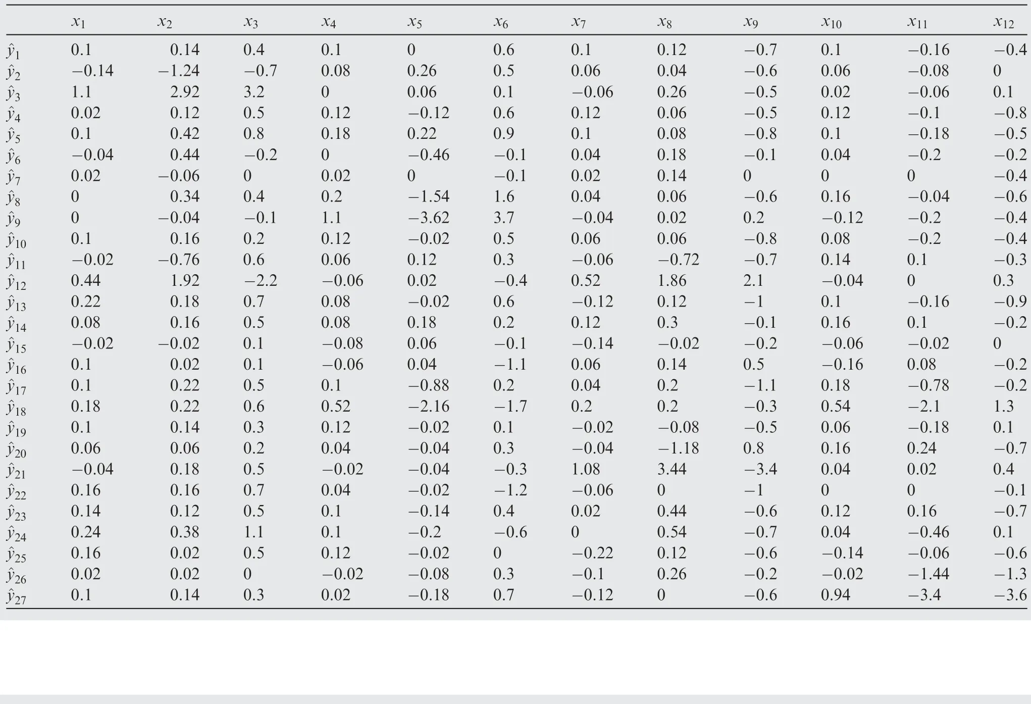
Table A3 Coefficient matrix between the displacements of actuators and panel shape control points.
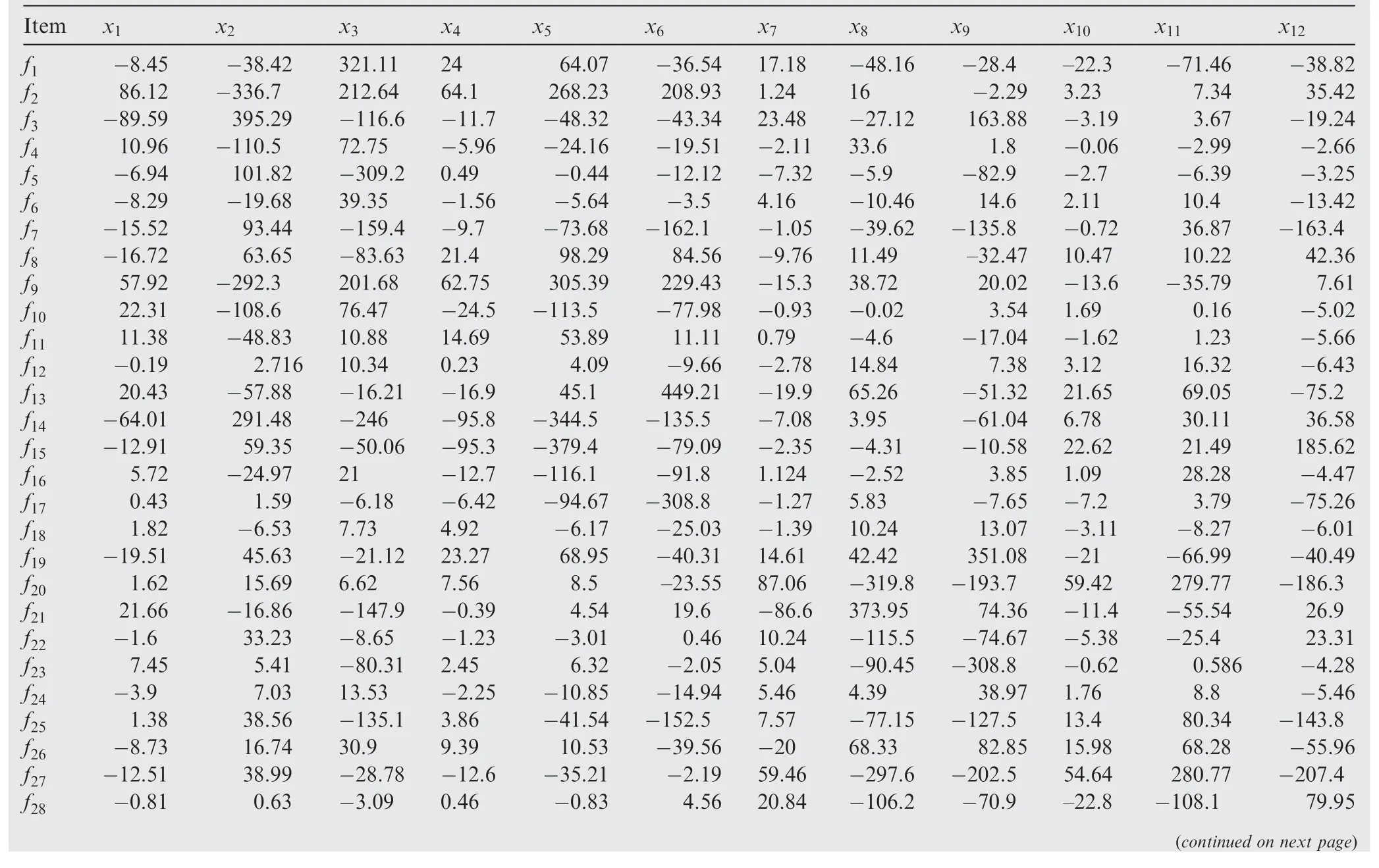
Table A4 Coefficient matrix between the displacements of actuators and load applied by the actuators.
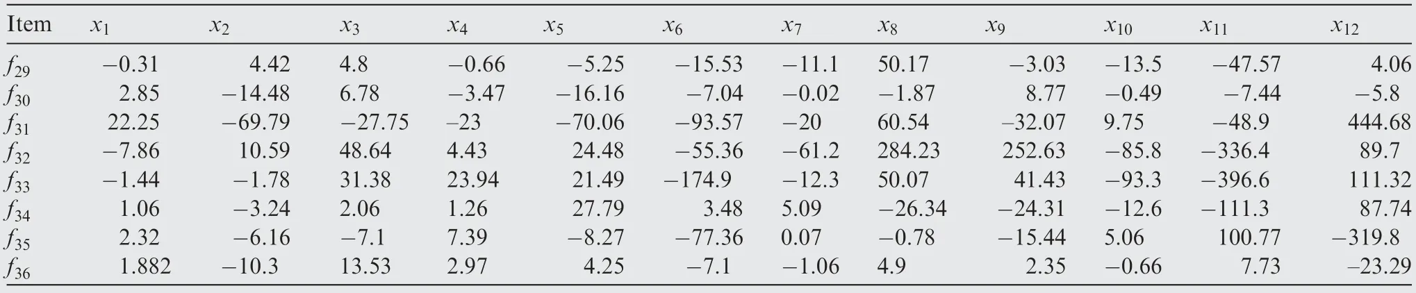
Table A4 (continued)

Table A5 Comparison of prediction values with experimental data of the panel shape control points displacements of optimized solution.

Table A6 Comparison of prediction values with experimental data of the deformation load of optimized solution.
杂志排行

CHINESE JOURNAL OF AERONAUTICS的其它文章
- Improving surface integrity when drilling CFRPs and Ti-6Al-4V using sustainable lubricated liquid carbon dioxide
- A hybrid chemical modification strategy for monocrystalline silicon micro-grinding:Experimental investigation and synergistic mechanism
- Analysis of grinding mechanics and improved grinding force model based on randomized grain geometric characteristics
- Experimental and modeling study of surface topography generation considering tool-workpiece vibration in high-precision turning
- Ultrasonic constitutive model and its application in ultrasonic vibration-assisted milling Ti3Al intermetallics
- Developing a novel radial ultrasonic vibration-assisted grinding device and evaluating its performance in machining PTMCs