Developing a novel radial ultrasonic vibration-assisted grinding device and evaluating its performance in machining PTMCs
2023-09-05BioZHAOBngfuWUYnsongYUEWenfengDINGJiuhuXUGuoqingGUO
Bio ZHAO, Bngfu WU, Ynsong YUE, Wenfeng DING,*, Jiuhu XU,Guoqing GUO
a National Key Laboratory of Science and Technology on Helicopter Transmission, Nanjing University of Aeronautics and Astronautics, Nanjing 210016, China
b Shanghai Spaceflight Precision Machinery Institute, Shanghai 201600, China
KEYWORDS Grinding force;Grinding temperature;Ground surface morphology;Particle-reinforcing titanium matrix composites;Radial ultrasonic vibrationassisted grinding
Abstract Particle-reinforcing titanium matrix composites(PTMCs)exhibit the sharp raising applications in modern industries owing to its extraordinary physical and mechanical properties.However,the poor grindability and unstable grinding processes due to the existence of TiC particles and TiB short fibres inside PTMCs,leading to the sudden grinding burn and low material removal rate.In this work, a novel radial ultrasonic vibration-assisted grinding (RUVAG) device with a special cross structure was developed to improve machining efficiency and avoid grinding burns.Meanwhile, the resonant modal and transient dynamic characteristics of radial ultrasonic vibration system were discussed.Comparative grinding performance experiments were then conducted under the conventional grinding(CG)and RUVAG using mono-layer cubic boron nitride abrasive wheels,in views of the grinding forces and force ratio,grinding temperature,and ground surface morphology.Results show that the ultrasonic vibration direction can be transformed effectively using the special cross structure of vibration converter,and better vibration homogeneity can be obtained.RUVAG has a smaller tangential grinding force by 5.0%–17.2%than that of CG,but a higher normal grinding force of 6.5%–14.9%, owing to the periodic impact of grinding wheels.In addition, RUVAG possesses a remarkable lower grinding temperature in range of 24.2%–51.8%and a higher material removal rate by 2.8 times compared with CG, resulting from the intermittent cutting behavior between the grinding wheel and workpiece.In this case, the sudden burn can be avoided during high-speed grinding processes.Moreover, the proportion of micro-fracture defects on machined surface is slightly increased once the ultrasonic vibration mode is employed because of the periodic impact on reinforced particles, whereas the pull-out defects of reinforced particles are reduced significantly.
1.Introduction
Presently, particle-reinforcing titanium matrix composites(PTMCs)have already received high attentions in manufacturing critical components in aerospace and high-grade vehicle industries because of their superordinary comprehensive properties, including excellent creep-resistance, anti-fatigue,corrosion-resistance and high temperature-resistance performances.1,2Grinding as the final machining method and core manufacturing procedure, was usually applied to obtain the high dimensional accuracy and quality of critical components.3,4However,the sudden grinding burn and induced poor machining quality were essentially impossible to avoid due to the continuous contact between the abrasive grains and workpiece,as well as the various surface defects caused by removing reinforced phases (i.e.TiC particles and TiB short fibres).5–7As a result,the grinding efficiency and quality could be hardly improved when grinding PTMCs.
Recently, ultrasonic vibration-assisted machining has been a promising hybrid method.Here,an additional vibration with ultrasonic frequency and micro amplitude was superimposed on a tool or workpiece during machining.8,9Especially, the ultrasonic vibration-assisted grinding (UVAG) has elicited considerable attentions due to the smaller grinding force,lower grinding temperature and better surface quality.10–12In addition, the UVAG with workpiece vibration could obtain a higher machining efficiency than the other one due to its high grinding speed regardless of the limitation of tool size.Numerous studies have focused on the influences of applied vibration directions (i.e.axial, tangential, and radial) and associated material removal mechanism during ultrasonic vibrationassisted grinding with workpiece vibration.Gao et al.13proposed a theoretical model of surface roughness in axial ultrasonic vibration-assisted grinding (AUVAG).Results indicated that the grinding speed and depth of cut had great effects on the surface roughness.In addition, the critical ductile cutting depth could be improved by 30 % during the AUVAG of ZrO2ceramic materials in comparison with the conventional grinding (CG).Sun et al.14also established the matching relationship model between the ground surface roughness, grinding parameters and ultrasonic amplitude under the AUVAG.They reported that the surface roughness could be improved by the AUVAG with a higher depth of cut compared with CG.Das et al.15developed an AUVAG device and evaluated the performance of device, in terms of grinding forces and machined surface roughness.Grinding forces and ground surface roughness could be remarkably reduced during grinding ZrO2ceramic materials using the AUVAG device.Tawakoli et al.16applied the axial ultrasonic vibration in the dry grinding of 42CrMo4 steel to reduce the consumption of cutting coolants.The results demonstrated that ultrasonic grinding could reduce the surface roughness, normal grinding force and thermal damage, where the normal grinding force could be reduced by 60%.However,these fundamental problems, such as sudden grinding burns caused by inadequate cooling conditions, could be not well solved because of lack of separation and larger actual contact length between grains and workpiece during AUVAG.
Along this line of consideration, applying tangential or radial ultrasonic vibration direction in grinding was worth studying due to the periodically contact and separation phenomenon between grains and workpiece.For the tangential ultrasonic vibration direction, Bhaduri et al.17evaluated the machining performance during tangential ultrasonic vibration-assisted grinding (TUVAG) of γ-TiAl intermetallic alloy with diamond wheels.The maximum grinding forces were reduced by 35 %, and the grinding ratio was increased within the range of two to seven times compared with that of CG.Cao et al.18proposed an ultrasonic vibration plate device and carried out the TUVAG experiments of Inconel718 superalloys.It was found that the TUVAG could reduce the grinding force,which was attributed to the intermittent cutting behavior and acoustic softening effects.Nik et al.19conducted the CG and TUVAG experiments of Ti–6Al–4 V using different grinding parameter levels.They concluded that TUVAG could still obtain the better surface quality under higher depth of cut and feed rate in comparison to CG.Abdullah et al.20studied the material removal mechanism during TUVAG of Inconel738LC superalloys without coolants.They revealed that the proportions of sliding and ploughing processes could be reduced or even eliminated, owing to the intermittent cutting behavior between grains and workpiece under ultrasonic vibration.As a result, the thermal damage could be alleviated during dry grinding process.Paknejad et al.21investigated the influences of tangential ultrasonic vibration parameters on grinding temperature during the creep-feed dry grinding of X20Cr13 martensitic stainless-steels.The lower grinding temperature and smaller thermal damage depth could be obtained by employing tangential ultrasonic vibration into grinding processes.
Similarly,for the radial ultrasonic vibration direction,Spur et al.22experimentally studied the grinding performance of ceramics during the radial ultrasonic vibration-assisted grinding (RUVAG).They pointed out that the RUVAG enormously reduced the normal grinding forces with a slightly increase in wheel wear and surface roughness.Akbari et al.23developed a compact radial ultrasonic vibration device to machine alumina ceramic materials.It was found that the surface roughness was improved by 8%and grinding forces were reduced by 22 %, resulting from the better self-sharpening ability of diamond wheels and the probable material brittle fracture by hammer impacts.Shen et al.24studied the wear characteristics of diamond wheels in RUVAG of ceramics materials.The grinding forces and force ratio were increased slightly as the cumulative material removal volume raised,owing to the improved self-sharpening ability caused by ultrasonic vibrations.Obviously, the RUVAG method contributed to the improvement of machining efficiency and quality due to the hammer impact and self-sharpening ability, especially for hard and brittle materials (e.g.PTMCs).However, the above fabricated ultrasonic vibration devices lacked the effective theoretic guidance.Furthermore, the application of RUVAG with workpiece vibration in high-speed grinding process was less explored.In this case,the development of a novel RUVAG device played a crucial role in achieve the high machining efficiency and desired quality of PTMCs.The effect of radial ultrasonic vibration direction on the high-speed grinding process needed be further studied.
In the current study, a novel RUVAG device with workpiece vibration was initially developed based on the apparent elastic method and finite element method(FEM).The grinding performance was then evaluated by adopting this device during grinding PTMCs.After the introduction section, the RUVAG system and corresponding operating principle were presented.Subsequently, the coupled vibration frequency equation of vibration converter and structure parameters design were discussed in detail.The FEM was adopted to verify the reliability of theoretical design by analyzing the resonant modal and transient dynamics characteristics of vibration converter.Prior to the grinding performance trials with PTMCs using a monolayer order-arranged cubic boron nitride (CBN) wheel, the vibration property of the fabricated RUVAG device was detected by a 3D laser Doppler vibrometer.Finally, the conclusions were summarized in the last section.
2.Development of RUVAG device
2.1.Operating principle of RUVAG device
Fig.1 illustrates the developed RUVAG device, which mainly consists of an ultrasonic generator and a radial ultrasonic vibration structure.Two transducers, two horns and one vibration converter are amalgamated to form the radial ultrasonic vibration structure.Specially,the vibration converter is a 3D cross structure.The operating principle of RUVAG device can be classified into the following steps: (i) The high frequency electrical signal produced by ultrasonic generator is exported to the transducers, and then the high frequency electrical signal is transformed into mechanical vibration with same frequency by the piezoelectric ceramics of transducer.(ii) The generated mechanical vibration from transducer is received and magnified by the horn.(iii)The mechanical vibration from the horn is superposed on vibration converter and the special cross structure can convert the horizontal mechanical vibration into vertical mechanical vibration.(iv) Once workpiece is fixed at the top surface of vibration converter and the vertical mechanical vibration is transmitted to the ground workpiece.In this case, the workpiece can vibrate along the radial direction of abrasive wheel and the radial ultrasonic vibration-assisted grinding technology can be realized.
As mentioned before, the vibration converter can convert the mechanical vibration direction, which based on the Poisson’s effect of materials.In detail, when a geometric body occurs longitudinal deformation under the action of external force,the corresponding transverse deformation will be generated.The ratio of longitudinal deformation and transverse deformation presents the Poisson’s ratio.Usually, the transverse deformation of geometric body is ignored, because the transverse deformation less than longitudinal deformation.In this work, the special 3D cross structure of vibration converter was design to form the coupled longitudinal deformation in three directions.When a high frequency mechanical vibration act on the longitudinal direction (x direction) of vibration converter, the other direction (y and z directions)can produce the same frequency mechanical vibration.In other words, the horizontal ultrasonic vibration can be transformed into vertical ultrasonic vibration by the vibration converter.
2.2.Design of geometry parameters
The coupled longitudinal deformation of vibration converter mainly depends on its geometry parameters, which is determined by the coupled vibration frequency equation.The vibration converter can be considered to consist of one central coupler and six extended bodies,as shown in Fig.2.The coordinate origin is assumed as the geometric centre of the vibration converter, and the geometric lengths of vibration converter and central coupler are defined as lx, ly, lzand hx,hy, hzat three axis directions, respectively.According to the 1D wave equation of a bar,the displacement and stress of central coupler and extended body are derived, respectively.Subsequently, based on the equivalent displacement and stress boundary condition at the interface between central coupler and extended body, the coupled vibration frequency equation of the vibration converter is established.

Fig.1 Schematic of radial ultrasonic vibration-assisted grinding system.
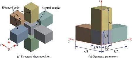
Fig.2 Illustrations of 3D cross structure of vibration converter.
2.2.1.1D wave equation
For a uniform cross-section bar, its 1D wave equation under condition of harmonic vibration can be expressed as follows25,26:
where u is the displacement distribution of bar, k = 2πf/C is the wave number, f is the ultrasonic vibration frequency, C= (E/ρ)1/2is the longitudinal wave velocity, E and ρ are the elastic modulus and density of the material, respectively.
According to Eq.(1), the distribution of displacement and stress of bar (Fig.3) can be obtained:
where a and b are constants, which is determined by the boundary conditions of the bar.
2.2.2.Displacement and stress distribution of central coupler and extended body
The vibration of central coupler in each direction satisfies the 1D wave equation.Based on the boundary conditions u(0)=0 and σ(0)=σ,the displacement distribution of central coupler in three directions can be calculated from Eqs.(2) and (3):

Fig.3 Displacement and stress distribution of bar under longitudinal vibration.

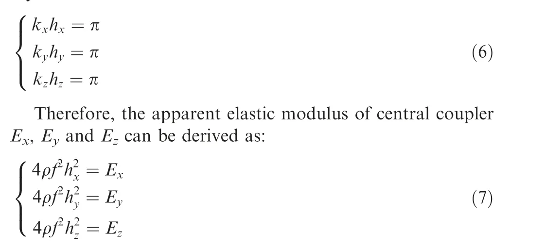
The apparent elastic modulus of central coupler can be defined by the apparent elasticity method (AEM).28,29The AEM regards the central coupler as anisotropy materials with different apparent elastic modulus in three directions,which is different from the macroscopic elastic modulus of materials.In this work,the vibration of the central coupler in each direction satisfies the half wavelength resonance condition, the boundary condition can be then obtained:
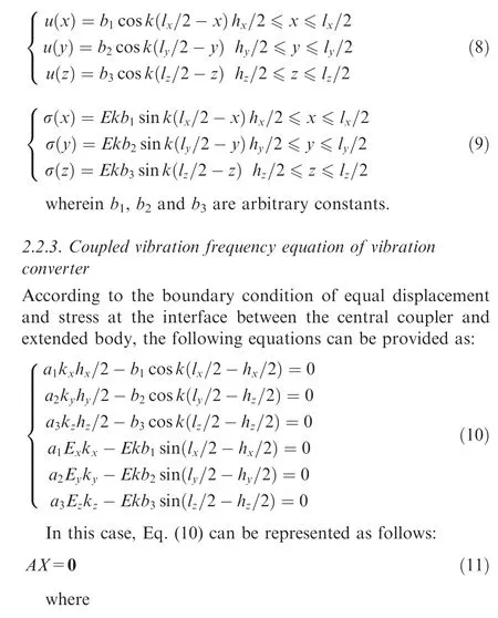
Based on the boundary conditions u(l)=U and σ(l)=0,U is the displacement imposed by external excitation.The displacement and stress distribution of extended body in three directions can be derived from Eqs.(2) and (3):
As seen from Eq.(15), the geometric parameters of the vibration converter can be obtained by altering the ultrasonic frequency, density and elastic modulus of material.However,the coupled vibration frequency equation of the vibration converter has a series of solutions.For the convenience of application, this study sets the special boundary conditions that lx=ly= lz= l,and hx= hy= hz=h.As a result, the coupled vibration frequency equation of vibration converter can be simplified as
In this work,the adopted material to fabricate the vibration converter is 316L stainless steel, and the associated properties values are listed in Table 1.Fig.4 depicts the relationship between the resonant frequency f and geometric parameters(e.g.l and h) of the vibration converter.A rapid decline and then gradual slowing down of resonant frequency can be observed as the length of vibration converter increases in range of 40–200 mm regardless of the variation of the central coupler length h.
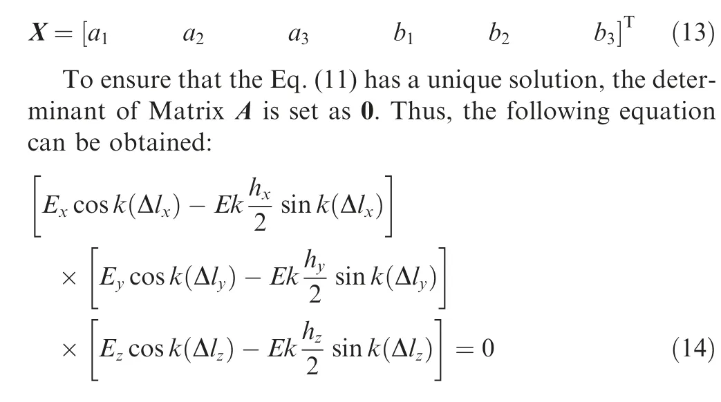
where Δlx= (lx- hx)/2, Δly= (ly- hy)/2, and Δlz=(lz- hz)/2.
Substituting Eq.(7)into Eq.(14),the coupled vibration frequency equation of the vibration converter can be expressed as
When the vibration converter length l kept a constant, the resonant frequency was always lower at a higher central coupler length,as plotted in Fig.4(a).When the geometric parameters l and h were fixed at 20 mm and 40 mm, the resonant frequency of vibration converter reached 126.7 kHz.With the increase of length l to 80 mm, the resonant frequency f remarkably decreased to 42.1 kHz.Once the length l increased to 200 mm, the resonant frequency slightly decreased by67.0 % to 13.9 kHz.When the length h was fixed at 30 mm,40 mm,50 mm,and 60 mm,a similar tendency of resonant frequency could be observed.As seen from the fitted curve in Fig.4(b), the relationship equation between the resonant frequency f, central coupler length h and vibration converter length l can be obtained as

Table 1 Materials properties of 316L stainless steel.
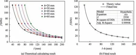
Fig.4 Effects of geometric parameters on resonant frequency of vibration converter.
According to Eq.(17), the resonant frequency associated with different lengths of vibration converter can be calculated.The resonant frequency of the vibration converter is designed as 20 kHz.To reduce the influence of length h on the transverse vibration of vibration converter, the length h should be less than the quarter wavelength of 316L stainless steel materials(h ≤4C/f).30Therefore, the length h is selected as 40 mm,and the length l is calculated as 166.5 mm.
2.3.Finite element analysis
2.3.1.Modal analysis of vibration converter
To verify the theoretical design accuracy of vibration converter, the 3D model of vibration converter with h = 40 mm and l = 166.5 mm was established and the corresponding vibration modal was analyzed by FEM.Fig.5 shows the associated analysis result.The simulated resonant frequency of vibration converter is 19032 Hz (Fig.5(a)) and the relative error is only 4.8 % compared with the designed resonant frequency, proving the reliability of this theoretical design (Eq.(17)).The vibration converter should be fixed to raise the system stiffness, so the vibration modal of vibration converter that imposed fixed constraint conditions needs further investigation.After imposing the fixed constraint at y axis direction,the simulated resonant frequency of the vibration converter reveals a rapid declination to 17603 Hz (Fig.5(b)).Fig.5(c)depicts the relative vibration displacement distribution of vibration converter at three axis directions with fixed constraint of y axis direction,which is consistent with the displacement distribution of bar (Fig.3).In addition, the relative vibration displacements of end surface are 23.3 at x and z axis directions, whereas the displacement at y axis direction is already near zero.This phenomenon implies that the ultrasonic vibration direction can be transformed at x and z axis directions.
Based on the above analyses,applying fixed constraint conditions on vibration converter result in the offset of resonant frequency, so the resonant frequency should be modified by altering geometric parameters of vibration converter.From the influence of length l on resonant frequency f as plotted in Fig.6, the linear relationship (i.e.f = -141 l + 17519) can be observed.Obviously, when the length l of vibration converter is 149 mm, the resonant frequency reaches 19985 Hz,

Fig.5 FEM modal analysis result of vibration converter.

Fig.6 Effects of length l of vibration converter on resonant frequency.
which is close to the designed frequency (20000 Hz).In this case, the length l of vibration converter is fixed at 149 mm.
2.3.2.Simulation analysis of vibration characteristics of RUVAG device
In this study, the transducer and horn were fabricated on the basis of the resonant frequency of 20 kHz.The RUVAG device was then completed after assembling the vibration converter, transducer and horn together.Prior to the verification trial, the vibration characteristics of RUVAG device (e.g.modal analysis, harmonic response analysis and transient structural analysis) was performed after bonding the workpiece on the top surface of vibration converter, as illustrated in Fig.7.The workpiece is PTMCs with a dimension of 30 mm (in length) × 15 mm (in width) × 10 mm (in height).
Fig.7(a) and 7(b) show the established 3D simulating model and simulated resonant vibration mode of RUVAG device, respectively.The applied constraint conditions of model are consistent with the actual experimental conditions.The uniform distribution of displacements on workpiece surface can be detected at the simulated resonant frequency of 19976 Hz.As seen from the harmonic response analysis curve between the amplitude and frequency at z axis direction of the workpiece (Fig.7(c)), a sharp peak tendency can be observed.When the frequency is 19980 Hz, the amplitude reaches the maximum value, indicating that the RUVAG device stays in resonance.Fig.7(d) depicts the transient structural analysis curve between the time and displacement at three axis directions.The sinusoidal displacement function (f(t) = Asin(2πft)) is adopted on the piezoelectric ceramics of transducers under the vibration condition: the amplitude of 1 μm and the frequency of 19976 Hz.The resolving time is set as 20 cycles of vibration(t=20/f=1×10-3s).Obviously,the vibration displacements are 0.1 μm and 0.2 μm at × and y axis directions,respectively,whereas the vibration displacement at z axis direction reaches 8 μm.These outcomes imply that the transform of ultrasonic vibration direction can be realized.
3.Vibration characteristic test

Fig.7 Simulated vibration characteristics of RUVAG device.
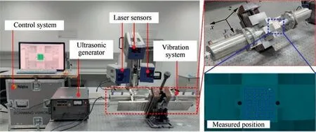
Fig.8 Measurement setups of vibration displacement for RUVAG device.
Based on the above theoretical analysis, the experimental RUVAG prototype was fabricated, and the associated vibration characteristic was then tested under a 3D laser Doppler vibrometer (PSV-500), as shown in Fig.8.The frequency sweep analysis test was first conducted to ensure the resonant frequency and then the constant frequency analysis was done to obtain the resonance vibration mode.The scope of the frequency sweep analysis was set in range of 15–25 kHz, and the driving voltage of ultrasonic generator was fixed at 40 V.
Fig.9 displays the detecting result on the top surface of the workpiece at z axis direction.When the frequency was 19718 Hz, the vibration amplitude reached the maximum value, which was remarkably higher than the other vibration directions(Fig.9(a)).Subsequently,the vibration displacement after applying the driving frequency (i.e.19718 Hz) on RUVAG device by adjusting ultrasonic generator.The minimum or maximum values of the vibration displacement could be reached at the same time,revealing the uniformity of vibration on the detected surface of RUVAG device.When the workpiece was attached on the top surface of RUVAG device,the similar phenomenon could be observed (Fig.9(b)).The vibration frequency was declined into 19617 Hz, and the relative error was only 1.9%compared with the designed resonant frequency.In addition, the consistency of vibration direction and uniformity of vibration displacement could be detected on the top surface of workpiece, satisfying the requirements of grinding trials.
4.Grinding performance evaluation using RUVAG device
4.1.Experimental setup

Fig.9 Amplitude-frequency curves and resonance vibration mode under different conditions.
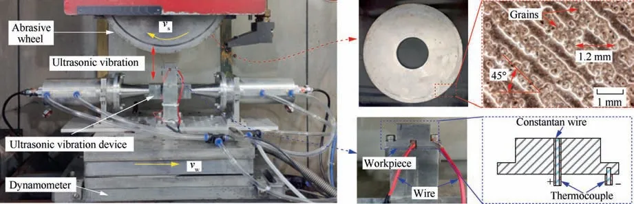
Fig.10 Experimental setups based on RUVAG device.
In this work, the previous developed monolayer orderarranged CBN wheel was applied to evaluate the grinding performance using RUVAG device assembled on a high speed and precision grinder(BLOHM MT-408),as shown in Fig.10.The wheel diameter and grinding width were 400 mm and 10 mm.The applied CBN grain size was 80/100#, which was arranged along the wheel circumferential with oblique rows of 45° and spacing of 1.2 mm.The adopted workpiece was PTMCs materials with the volume fraction of 10vol% reinforced phases (i.e.TiC particles and TiB short fibers) and Ti–6Al–4 V matrix materials.The composition and mechanical properties of PTMCs as well as grinding parameters are listed in Tables 2 and 3.In addition, the three-way piezoelectric dynamometer (HR-FP3407, H&T HORIZON) and semithermocouple device were employed to detect grinding forces and temperature.Furthermore, the ground surface morphologies were detected via an optical microscope (KH-7700) and scanning electron microscopy(SEM;COXEM EM-30)at various material removal rates.
4.2.Results and discussion
4.2.1.Grinding forces
Fig.11 depicts the grinding forces and force ratio with the variations of grinding parameters under CG and RUVAG.When the workpiece speed vwand depth of cut apwere fixed at 3 m/min and 40 μm, the normal grinding force Fnand tangential grinding force Ftremarkably decreased as the grinding speed increased for both grinding types(Fig.11(a)).However,compared with the lower value of Ft,the RUVAG always had a higher value of Fnthan that of CG.As the grinding speed vsincreased from 90 m/s to 120 m/s, Fnslightly decreased in range of 69.2–44.6 N under CG.For RUVAG, Fntended to decline from 72.6 N to 51.3 N.An increase of Fncould be obtained by 6.5 %–14.9 % under RUVAG compared with CG.However, Fttended to slightly decrease from 22.3 N to 15.2 N,by 31.8%under CG.RUVAG had a smaller Ft,ranging from 19.8 N to 14.9 N,by 24.7%.As seen from Fig.11(b)and 11(c), the similar uptrend of Fnand Ftcan be observed regardless of the grinding type and changed grinding parameters.Specifically, Fnsharply increased as vwincreased in range of 1–7 m/min from 49.7 N to 77.1 N,by 55.1%under CG and from 56.8 N to 87.3 N, by 53.7 % under RUVAG.Fnslightly increased from 15.5 N to 25.8 N, by 66.5 % under CG and from 15.6 N to 23.8 N, by 52.6 % under RUVAG.When apvaried from 20 μm to 80 μm, RUVAG had a higher Fnby 7.4 %–12.3 % and a lower Ftby 4.8 %–13.9 % than those of CG.Subsequently, the sharpness of CBN wheels under different grinding types was further evaluated on the basis of the variation of grinding force ratio Fn/Ftas the material removal rate Qwincreased (Fig.11(d)).A stable Fn/Ftvariation can be observed for both grinding types, indicating the excellent sharpness of CBN wheels.Furthermore, the influence of worn grain on grinding processes can be ignored due to the slight wear of CBN grains.

Table 2 Composition and mechanical properties of PTMCs.
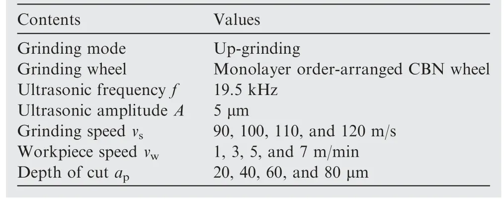
Table 3 Grinding parameters.
Based on the above analysis result, RUVAG has a higher Fnvalue for the following two reasons.(i) An instantaneous acceleration of CBN grains relative to workpiece can be obtained when the radial ultrasonic vibration is applied to workpiece.The maximum acceleration can reach 75000 m/s2with the ultrasonic frequency of 19.5 kHz and amplitude of 5 μm.In this case, a large instantaneous impact force acts on the workpiece once the grain contacts with the workpiece.(ii)RUVAG has a larger grinding depth under the radial ultrasonic vibration effect, leading to the increase of maximum undeformed chip thickness and thus the higher grinding force,as shown in Fig.12.In addition,the reason for Ftforce reduction attributes to the effects of grains overlapping actions and intermittent cutting behavior,which produced the shorter chip length.31,32In this case,the cutting stage was the main materials removal method, and the proportions of sliding and ploughing were reduced, resulting in the decrease of friction forces.
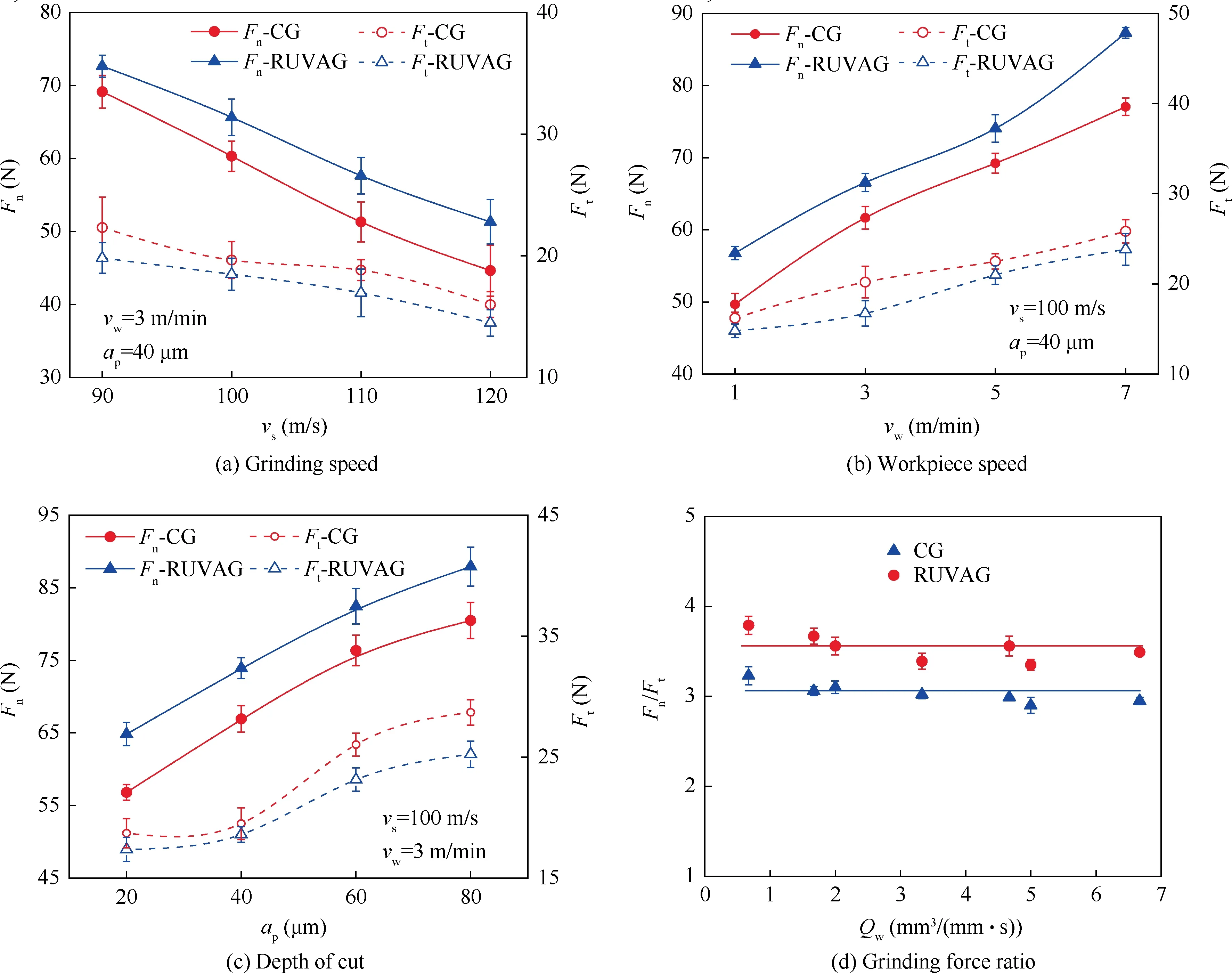
Fig.11 Effects of grinding parameters on grinding forces and force ratio vs the material removal rate.

Fig.12 Schematic illustration of grain trajectory of CG and RUVAG.
4.2.2.Grinding temperature

Fig.13 Effects of grinding parameters on grinding temperature.
Fig.13 shows the grinding temperature with the variations of grinding parameters under CG and RUVAG.The grinding temperature tended to rapidly increase as grinding parameters(e.g.vsvw,and ap)increased for both grinding types.When vwand apwere fixed at 3 m/min and 40 μm,CG had a significant increase in grinding temperature from 332 ℃to 603 ℃, by 81.6%as vsranged from 90 m/s to 120 m/s(Fig.13(a)).However, for RUVAG, the grinding temperature tended to have a slight lower value in range of 160–457 ℃than that of CG.The temperature reduction rate reached 31.9%once the ultrasonic vibration was adopted at the grinding speed of 120 m/s.The reasons for the increase in grinding temperature as vsincreased fall under two aspects.(i) Amounts of grinding heat is generated as the specific grinding energy required for material removal increases under the high grinding speed.(ii) The existence of gas barriers hinders the cutting fluid flowing into grinding arc area, and the produced grinding heat is difficult to transfer to the cutting fluid, as displayed by Qiu et al.33The similar uptrend tendency of grinding temperature can be observed in Fig.13(b) and 13(c).Specifically, when vwranged from 1 m/min to 7 m/min,RUVAG had a lower grinding temperature from 161 ℃to 460 ℃than that of CG in the range of 248 ℃–693 ℃.The temperature reduction rate reached 33.6 %–45.6 % under RUVAG.As seen from the variation curve of grinding temperature as a function of ap, the temperature had a rapid linear increase from 243 ℃to 639 ℃as apraised within the scope of 20–60 μm under CG.Subsequently,a slight uptrend from 639 ℃to 703 ℃was detected when apreached 80 μm.For RUVAG,a linear increase in temperature from 150 ℃to 511 ℃can be observed when apincreased in the range of 20–80 μm.The temperature reduction rate reached 27.3%–41.5%under RUVAG.The reduction in temperature under RUVAG processes can be concluded for the following reasons.(i)The amount of generated heat was lower than that of CG processes due to a smaller tangential force between the CBN wheel and workpiece.(ii)The intermittent cutting behavior of ultrasonic vibration is conducive to cutting fluid entering the grinding arc area and thus reduce the grinding temperature of workpiece.34–36.
Based on the above analysis on grinding temperature, the influence of the material removal rate Qw(Qw= vw∙ap) on grinding temperature should be further investigated.This is because the existence of Ti–6Al–4 V alloys inside PTMCs materials can easily cause burns on workpiece surface, so the improvement of Qwwas highly limited.Fig.14 shows the rapid increase in grinding temperature as Qwincreases from 0.67 mm3/(mm∙s)to 11.67 mm3/(mm∙s)regardless of the grinding types.In addition,RUVAG has a lower temperature compared with CG.Specifically, when Qwreached 3.33 mm3/(mm∙s), the grinding temperature exhibited a linear increase to 592 ℃, which was close to the critical burn temperature of PTMCs(600 ℃).The partial slight burn on workpiece surface can be clearly observed with the stripes of yellow and black.When Qwreached 4.67 mm3/(mm∙s), the workpiece surface was severely burned with the stripes of dark yellow and purple-dark.By contrast, when Qwwas less than 3.33 mm3/(mm∙s), RUVAG had a lower grinding temperature (322 ℃),which was far below that of CG processes.When Qwwas 9.33 mm3/(mm∙s), the grinding temperature reached 590 ℃under RUVAG.With the increase of Qwto 11.67 mm3/(mm∙s),RUVAG has a larger temperature of 650 ℃, and a large area of burns can be detected on workpiece surface.Along this line of consideration, the material removal rate of PTMCs can be improved by 2.8 times without burns by employing radial ultrasonic vibration during grinding.
4.2.3.Machining surface defects
PTMCs, as non-homogeneous materials, consist of reinforced phases and titanium matrix alloys.In this case, the removal characteristics of TiC particles and TiB short fibres inside PTMCs have a strong impact on the ground surface quality,such as void, macro-fracture and pullout, as studied by Li et al.7Fig.15 shows the machined surface micro-topography when Qwreached 3.33 mm3/(mm∙s) for both grinding types.Numerous micro-cracks on machined surface can be observed under CG processes owing to the burns.The voids of different sizes and depths on machined surface were also detected due to the pullout of macro-fractured reinforced phases.By contrast,when the radial ultrasonic vibration was applied on CG, no micro-cracks were detected, resulting from the reduction of grinding temperature.The voids still exist due to the pullout of micro-fractured reinforced phases.In this case, the size and number of voids under RUVAG were significantly less than that of CG processes.This phenomenon is possibly because the intermittent cutting behavior caused by the grain sinusoidal motion reduced the removal proportion of reinforced phases.In addition, the periodic impact of grains was applied on reinforced phases,which was conducive to the generation of micro-fractures of reinforced phases.Furthermore,the micro-fractured particles and titanium alloys matrix can be removed together.As a result,the machining surface defects can be effectively reduced and thus improve the ground surface quality.

Fig.14 Variations of grinding temperature as a function of the material removal rate.

Fig.15 SEM micrographs of machined surface at the material removal rate of 3.33 mm3/(mm∙s).
5.Conclusions
(1) Based on the Poisson’s effect of materials,the ultrasonic vibration direction can be transformed by special cross structure of vibration converter.According to the coupled vibration frequency equation of vibration converter, its vibration characteristics was determined by geometry parameters and materials properties.The resonant frequency error of RUVAG device between theory and test can reach 1.9 % using the FEM.The vibration uniformity of RUVAG device is well verified.
(2) Compared with CG, RUVAG has a lower tangential grinding force of 5.0%–17.2%but a higher normal grinding force of 6.5 %–14.9 %, which is different from the other literatures.This can be attributed to high frequency and high acceleration impact force and the increase of maximum undeformed chip thickness due to the application of radial ultrasonic vibration direction.
(3) RUVAG possesses a lower grinding temperature by 24.2 %–51.8 % and a higher material removal rate by a maximum of 2.8 times without burns compared with CG,owing to the intermittent cutting behavior.In addition, the machining surface defects can be effectively reduced by employing radial ultrasonic vibration.
Declaration of Competing Interest
The authors declare that they have no known competing financial interests or personal relationships that could have appeared to influence the work reported in this paper.
Acknowledgments
This work was financially supported by the National Natural Science Foundation of China (Nos.51921003, 92160301,52175415 and 52205475), the Science Center for Gas Turbine Project (No.P2022-A-IV-002-001), the Natural Science Foundation of Jiangsu Province (No.BK20210295), the Superior Postdoctoral Project of Jiangsu Province (No.2022ZB215),the Open Foundation State Key Laboratory of Mechanical Transmissions(No.SKLMT-MSKFKT-202101),and the Special Projects for the Reengineering of Industrial Foundation and the High-quality Development of Manufacturing Industry(No.TC210H02X).
杂志排行

CHINESE JOURNAL OF AERONAUTICS的其它文章
- Improving surface integrity when drilling CFRPs and Ti-6Al-4V using sustainable lubricated liquid carbon dioxide
- A hybrid chemical modification strategy for monocrystalline silicon micro-grinding:Experimental investigation and synergistic mechanism
- Analysis of grinding mechanics and improved grinding force model based on randomized grain geometric characteristics
- Experimental and modeling study of surface topography generation considering tool-workpiece vibration in high-precision turning
- Collaborative force and shape control for large composite fuselage panels assembly
- Ultrasonic constitutive model and its application in ultrasonic vibration-assisted milling Ti3Al intermetallics