Driver Intent Prediction and Collision Avoidance With Barrier Functions
2023-03-09YousafRahmanAbhishekSharmaMrdjanJankovicMarioSantilloandMichaelHafner
Yousaf Rahman,Abhishek Sharma,Mrdjan Jankovic,,Mario Santillo,and Michael Hafner
Abstract—For autonomous vehicles and driver assist systems,path planning and collision avoidance algorithms benefit from accurate predictions of future location of other vehicles and intent of their drivers.In the literature,the algorithms that provide driver intent belong to two categories: those that use physics based models with some type of filtering,and machine learning based approaches.In this paper we employ barrier functions (BF)to decide driver intent.BFs are typically used to prove safety by establishing forward invariance of an admissible set.Here,we decide if the “target”vehicle is violating one or more possibly fictitious (i.e.,non-physical) barrier constraints determined based on the context provided by the road geometry.The algorithm has a very small computational footprint and better false positive and negative rates than some of the alternatives.The predicted intent is then used by a control barrier function (CBF) based collision avoidance system to prevent unnecessary interventions,for either an autonomous or human-driven vehicle.
I.INTRODUCTION
KEY requirements for autonomous vehicles (AV) and vehicles equipped with advanced driver assist systems(ADAS) (for example,Level 3 autonomy) include the ability to plan and execute trajectories leading towards their destination while avoiding collisions.To do this competently,it is useful to predict intentions of the surrounding vehicles which we refer to as “targets.”For connected autonomous vehicles one could expect to have the (virtual) driver intent broadcast using vehicle to vehicle (V2V) communication.For hum and riven target vehicles such information is usually not available,though turn signals might be an indication of intent in many cases.As we shall show later,what one could consider“normal”driving requires a decision whether a target vehicle stays in its lane or leaves and crosses to the side of the “host”vehicle (i.e.,the vehicle doing the decision making and deciding what action to take).This motivates the development of algorithms that can predict the intent and motion of nearby vehicles without relying on explicit communication for collision avoidance.
Because prediction algorithms are always complementary to a larger planning algorithm,and may need to monitor up to a dozen vehicles in complex environments,it is critical that the prediction algorithm has a relatively small computational expense.Another issue often encountered in intent prediction is false positives and false negatives– for example,an algorithm classifying a lane change to the left as staying in the current lane or vice-versa.Reducing these mis-classifications is also essential for driver intent prediction algorithms.
There are several approaches in the literature related to intent prediction.Model based algorithms use a filtering or reachability computation based on a target vehicle dynamical model to project a vehicle’s motion forward.Due to relatively lower complexity,model based algorithms can be used for highway driving and are likely to performwell in those cases.However,this approach makes it difficult to utilize contextual information such as lane lines and obstacle locations.One example of a model based technique is the interacting multiple model (IMM) [1]−[3].The IMM can be used to predict vehicle intent by creating a behavioral mode for each different option that is available to a vehicle and then simply selecting the most likely mode (as determined by the IMM based on measurements of the vehicle state) as the intent of the vehicle.
Another class of methods for driver intent prediction are machine learning (ML) methods.These include Decision Trees [4],[5],long short term memory (LSTM) neural networks [6],[7],Gaussian mixture models (GMM) [8],[9].These algorithms rely on data-sets that have already been manually classified to learn how to classify trajectories by minimizing classification errors in the data set.A sample data point consists of a snippet of the vehicle’s motion (typically the last 0.5–1.0 s) and its classification.Depending on the algorithm,the road network and other environmental or contextual features may be used if available.
In this work we exploit contextual information using barrier functions (BF) for intent prediction.BF’s have been used to establish a safety certificate (e.g.,[10]),i.e.,to guarantee that a given system is safe in the sense that it will stay in the admissible set.For intent prediction,we propose placing fictitious,but road geometry based barrier constraints for nearby traffic based on road and monitoring the potential violation of these constraints.By considering the rate of change of the barrier function one can decide if the target vehicle will change lane before it actually crosses the lane boundary or if it will turn in the early part of maneuver.Compared to many multiple-model or ML based algorithms,the BF based intent prediction can achieve similar results with a lighter computational footprint in terms of memory requirements and computation time.The BF based intent prediction algorithm can also reduce false positives and negatives.This lane change intent prediction is an expanded version of a portion of the paper[11].
We then combine BF based intent prediction with a control barrier function (CBF) based collision avoidance system(CAS).The CAS takes the form of a safety filter that evaluates the safety of the nominal control action (from either human or virtual driver) and overrides it when deemed unsafe.The CAS relies on the quadratic program to arbitrate between several constraints that include other vehicles as well as lane and road boundaries.We use BF to gate,i.e.,turn on or off,the specific CAS constraints for a given target vehicle.We show that this approach reduces unnecessary interventions by the CAS,resulting in more predictable,human-like interventions in the sense that often an action produced by CAS without gating might be considered unnecessary under the circumstances.This paper does not explicitly consider vehicle social interactions.In examples in the paper,the behavior of the target vehicle could be erratic,e.g.,crossing the lane line into an oncoming traffic,most likely due to human error,ADAS system malfunction,or a mode confusion between the two.Including these possibilities into modeling of other agent behavior is completely outside the scope of this paper.
The rest of the paper is organized as follows.In Section II,we cover BF and CBF theory.Next in Section III,we show how BFs can be used to predict the intent of nearby vehicles.We show an example involving lane change detection and compare the performance with a GMM based approach.Section IV covers a CBF based collision avoidance system and a combination with the intent prediction from Section III.We show that using contextual information and intent prediction in collision avoidance systems reduces the amount and severity of their interventions,leading to an improved experience for passengers.In Section V we present conclusions to this work.
II.BARRIER FUNCTIONS
BFs have been used to enhance system robustness [10],while CBFs have been used as a method to provide minimally-invasive feedback control whilst satisfying multiple constraints placed on the system in order to ensure safety[12]−[15].Here we mix the two concepts because we would like to apply them to systems with control inputs that are outside of the host (the entity doing the calculations) control.Specifically,we would like to create and monitor barrier constraints for nearby vehicles,and use their adherence or violation to predict the vehicles intent.Consider a system that is affine in control
where x ∈Rnis the system state andu∈Rmis the control input.We assume that a control inputis computed by a driver (or an agent/controller) to achieve some unknown (to us) objective.The inputmay be estimated from observations or explicitly communicated by nearby vehicles as part of the Basic Safety Message.Few vehicles have V2V capabilities and so usually this must be estimated.We consider both the case whereis known or estimated and also the case where it i s unknown.Consider an admissible (safe) set C ⊂Rndefined as
whereh(x):Rn→R is a twice continuously differentiable function.Then,let the control objective be to maintain the forward invariance (defined below) of the set C.We assume that C is nonempty,that is,Int(C)≠∅.Fig.1 shows (2) pictorially.For (1),given a control inputthe functionh(x) is a BF [13]with respect to the admissible set C if
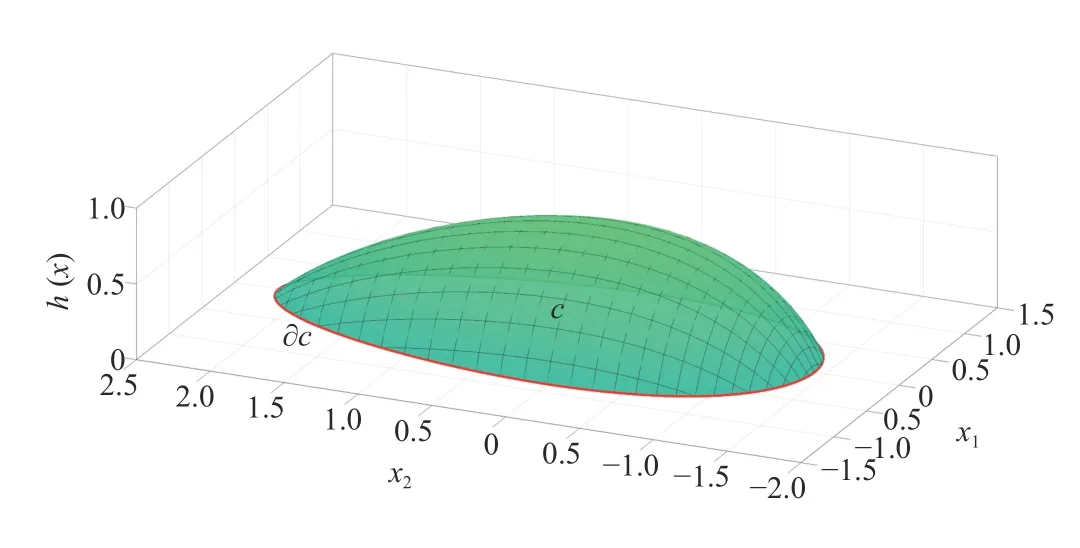
Fig.1.Example admissible set and boundary.
Here,we have restricted our attention to the linear function α(h)=l0h.However, α(h) can be any class-K function,i.e., α(h) is strictly increasing and satisfies α(0)=0.The above inequality means the BFh(x) cannot decrease towards 0 faster thanand,thus,the set C is forward invariant– any trajectory that starts in C stays in C for allt.
If a BF is relative degree 2 with respect to the control inputs(i.e.Lgh(x)=0,as is the case later in this paper) we can continue to use the 1st order constraint for intent prediction(although this constraint can no longer be used as a CBF,as discussed later).Doing so introduces the additional benefit of no longer requiring estimates or explicit communication of the target vehicles control input.Alternatively,we may use the 2nd order barrier constraint:[16].Here,l1andl0are selected such that the roots of the polynomials2+l1s+l0are negative real.We then monitor barrier constraint below:
A.Control Barrier Functions
A BFh(x) is a CBF with respect to the set C ifhis differentiable in Int(C),h(x)→0 as x →∂C,and
ifh(x) is relative degree 1 with respect to the control inputu.h(x)is relative degree 1 with respect to the control inputs if∃x ∈C:Lgh(x)≠0,where0denotes the zero vector.The definition(5)states that when the control inputhas no impacton thethe CBFh(x)cannot decrease towards 0 faster thanThe set C∗={x:h(x)>0)} is forward invariant.Ifh(x)is relative degree 2 with respect to the control input (i.e.,Lgh(x)=0 and ∃ x ∈C:Lg Lf h(x)≠0),thenh(x) is a CBF if
B.Intent Prediction With Barrier Functions
The key ingredient that allows the use of barrier functions for intent prediction is know ledge of road geometry.For example,by placing a barrier parallel to the lane lines,it can be used to detect lane changes by target vehicles.Similarly,if the intersection geometry is known,this information can be used to place barriers in such a way that the intent (i.e.,straight or left/right turn) of the target vehicle can be predicted.This is achieved by observing the value of either the 1st or 2nd order constraints depending on the information available.If the constraint value drops below a threshold (typically 0),a prediction can be made about the driver’s intent.In the case where the control inputs of the target are available or estimated,the second order barrier constraint below is used to predict driver intent based on (4) and (11):
If driver inputs are unavailable due to lack of V2V communication or inaccurate online estimation,the first order constraint below may be used to predict the driver intent using only the first two equations in (11):
The only vehicle model parameter required for the intent prediction algorithm is the target vehicle wheelbase,and in the case of the first order BF prediction algorithm no model information is required.
III.LANE CHANGE PREDICTION WITH BARRIER FUNCTIONS
A.Vehicle Model for Barrier Dynamics
We use a 3-DOF bicycle model for vehicle dynamics,where the 3 DOF are longitudinal,lateral,and yawing motion.For collision avoidance in urban and highway environments,such a model is usually sufficient.Denote byxthe system state:wherexandyare the position coordinates of a vehicle in an inertial coordinate system in meters[m],θis the angle of the vehicle longitudinal axis to thexaxis of the inertial coordinate system in rad,vlonis the longitudinal velocity andvlatis the lateral velocity,both in m/s.Then,the system dynamics can be approximated by the equations below[17]:
wherevis the absolute velocity in m/s,βis the slip angle,αis the longitudinal acceleration of the vehicle in m/s2,Faerois the aerodynamic drag,Ffis the lateral tire force on the front tire,Fris the lateral tire force on the rear tire,Mis the mass of the vehicle in kilograms [kg],Lfis the distance of the front wheel to the center of mass,Lris the distance of the rear wheel to the center of mass both in m,andIzis the yaw moment of inertia of vehicle in kg·m2.The lateral tire forces are calculated as follows:
whereCfis the cornering stiffness of each front tire,Cris the cornering stiffness of each rear tire,δis the front wheel angle in rad,ϕvfis the front tire velocity angle and ϕvris the rear tire velocity angle both in rad.
To compute the barrier dynamics in this section and in Section IV,we use a kinematic vehicle model shown below.For this model,we assume that the slip angles are negligibly small and that the steering angleδis sufficiently small such that tan δ ≈δ .These approximations aid in the calculation ofandThese simplifications and the kinematic model are discussed in [17,p.23–25].
B.Barrier Constraints for Lane Change Detection
The ability to predict lane changes by nearby traffic is important for detecting cut-ins or determining if an on coming vehicle in an adjacent lane is dangerous to the host,among other situations.This information could be used by a vehicle following control such as adaptive cruise control (ACC) or a longitudinal motion controller in a fully autonomous vehicle.The intent prediction algorithm assists the vehicle by giving it time to react to changes in its environment and also prevents unnecessary reactions.
To detect lane changes,we begin by using a vehicle-centric coordinate system.This aids in the derivation of barrier constraints and dynamics,and makes it easy to transform between vehicle and inertial coordinate systems.Next,we assume that lane information is encoded by the left and right lane polynomials that are available to the algorithm[18],[19].The left and right lane boundaries are expressed as 3rdorder polynomialspLandpRrespectively,as shown below and in Fig.2.
wherexis the longitudinal andyis the lateral coordinate in the target-centric reference frame (employed here for simplicity).

Fig.2.Barriers for detecting left and right lane changes.By placing hL and hR such that the barrier constraints are violated shortly before the left or right side of the target encroaches the lane line,early detection of lane changes is possible.
To detect a lane change,we use the BFs below:
whereyintis the perpendicular distance of the barrier to the lane line.The choice ofyintis an important design consideration.Ifyintis too small,the detection will be relatively late in the maneuver.Ifyintis too large,it may result in many false positives.LetCLandCRdenote the first or second (if available) order constraints for the left and right barriers respectively.
Then
The design parameters available in the algorithm areyint,l0,andl1.In the next section,we show how these parameters can be chosen optimally.In [11] we use a similar idea for detecting turns at an intersection and compare the algorithm with an IMM.
C.Lane Change Prediction System Optimization With Genetic Algorithms
To improve the prediction,we optimize the barrier geometry and the parametersl1andl0by minimizing the cost function below for a dataset consisting of 400 lane change trajectories at speeds ranging from 10–80 mph (4.5–36 m/s),with varying levels of abruptness in the lane change.To find good parameters we consider the following minimization problem:
whereNis the number of trajectories in the dataset,Mis a large positive number to penalize false positives,and the parameter vectorϕis given by
The detection timetdetis the time instance whereCL<0 ∨CR<0 is first satisfied,andtactis the time at which steering wheel starts turning for the lane change,and is known during the parameter optimization.The cost function (13) is the sum of the differences betweentdetandtactfor each sample in the dataset.Thus,minimizing (13) minimizes the average detection time delta of the data set.To optimizeϕ,we use a genetic algorithm with a population size of 200 candidates.The genetic algorithm was implemented using the ga function available in MATLAB.
D.Examples and Comparison
We compare performance of the BF lane change detection algorithm with a GMM [20],[21].GMM’s are probabilistic models that create soft clusters to which the data points may belong.The clustering is soft because the GMM quantifies the probability that a data point is a member of each cluster.This is different from hard clustering algorithms such ask-means clustering,where each sample is assigned to only one cluster.Soft clustering is useful in the context of intent prediction because in the case where the probabilities of two clusters are close (and therefore not close to 1),this measure of uncertainty may be used by the collision avoidance algorithm in its decision making.For example,it may behave as though both possibilities are true until a more definitive determination can be made.In the case of lane change detection,the clusters are left lane change,right lane change,and lane keeping.To create the model,we use the along track and across track (deviation from lane center) positions of the vehicle.This results in a very lightweight classifier for this application,with only 12 parameters (means and variances of each variable for every cluster) required to learn any data set.The GMM learns the parameters by using the expectation maximization (EM) algorithm.Once the GMM has been trained,the probability of a data point belonging to clusteriis calculated using Bayes’theorem.
whereNis the number of clusters.The classifier calculates the probability of samplexbeing in each cluster and assignsxto the cluster with the highest probability.The GMMis trained using the same data set as the BF lane change detection algorithm.
Fig.3 shows lane change detection using a GMM,1st and 2nd order BF for a lane change at 50 mph.The lane change is completed in approximately 3 car lengths.Both versions of the BF based detection system are able to predict the lane change sooner than the GMM.All three algorithms are able to predict a lane change before the center of the vehicle crosses the lane boundary.The 2nd order BF uses the steering input of the vehicle and is able to very quickly detect a left lane change.The information required by the 1st order BF and the GMM are similar.
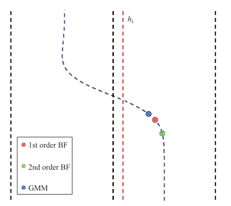
Fig.3.Cut-in detection locations for GMM and 1st and 2nd order BF for a high speed cut in at 50 mph.Note that the scale used for the across track axis(i.e.,perpendicular to the road) is different than the along track axis in order to exaggerate the cut in maneuver.
Fig.4 shows the mean preview time of 50 lane change maneuvers with varying initial position in the lane and abruptness (measured by lateral acceleration) at 4 different speeds for GMM,1st and 2nd order BF.The lane change preview time is defined as the difference between the time the left side of the vehicle crosses over the lane boundary and the time the intent is predicted.Higher preview times give the systemmore time to react to the lane change maneuver.For the 2nd order BF,we show both the BF prediction withknown and withestimated using longitudinal and lateral acceleration measurements.At low speeds,the GMM provides the most preview time,but at speeds approaching highway speeds,the 1st and 2nd order BFs both provide higher preview times than the GMM.In addition,the BF based methods can be tuned at different speeds,while no such option exists for the GMM since it uses only position measurements.
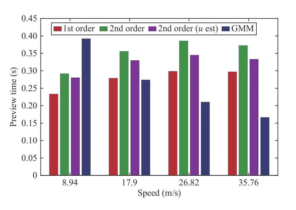
Fig.4.Average Preview Time provided by each method at different speeds(higher is better).The speeds correspond to 20,40,60,and 80 mph.
A key advantage of the BF based prediction is the increased likelihood that false negatives will be avoided.A false negative is defined as when a vehicle is undertaking a maneuver(i.e.,other than straight) but the intent prediction algorithm predicts that it is continuing along a straight path.When using BF based intent prediction,at some point during the maneuver the barrier constraints will be violated,and the algorithm will predict that the vehicle is undertaking a maneuver.The constraint violation may be late in the maneuver and thus the utility of the information may be diminished.False negatives are possible and can often occur for GMM and other ML based classifiers.
Fig.5 shows fal se positives for a lane change trajectory for the GMM,and 1st and 2nd order BF.The GMM has many false positives during the straight portion of the trajectory.
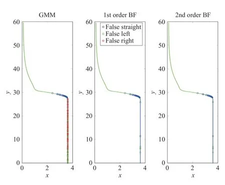
Fig.5.False Positives for a sample trajectory.
Tables I–III show confusion matrices for the data set for the GMM,1st,and 2nd order BF respectively.The columns of the matrix denote actual intent and the rows denote estimated intent.The values are expressed as percentage of the actual intent classified in each row.The GMM misclassifies almost 40% of straight samples as left or right lane changes,while the 1st and 2nd order BF misclassify 11% and 12% samples,respectively.

TABLE I CONFUSION MATRIX FOR THE GAUSSIAN MIXTURE MODEL

TABLE II CONFUSION MATRIX FOR THE FIRST ORDER BF ALGORITHM

TABLE III CONFUSION MATRIX FOR THE SECOND ORDER BF ALGORITHM
IV.CBF BASED COLLISION AVOIDANCE SYSTEM
In this section,we present a CBF based Collision Avoidance System that uses CBF to create constraints for a quadratic programs to compute the minimally invasive control that guarantees forward invariance of the safe set[12]−[15].
A.Control Barrier Function Problem Formulation
Consider the system with kinematic bicycle model dynamics (11) augmented with target vehicle location.
wherexTis the targetxposition andyTis the targetyposition.The steering command for the host is δ=δ0+δCBF,and the longitudinal acceleration for the host is α= α0+αCBF.δ0and α0are the nominal controls that may be computed by an automatic controller in the case of an AV or by a human driver in a conventional vehicle.While this controller primarily navigates the vehicle to the destination,safe navigation of the vehicle is guaranteed by a secondary CBF controller that enforces the barrier safety constraints.The combined optimization problem can then be formulated in the form as stated below:
whereHδis the weight on steering effort andHαis the weight on braking/acceleration.In practice,we set one ofHδorHα=1and scale the other weight depending on whether steering or braking is the preferred method of collision avoidance.SettingHα>>Hδeffectively makes the control biased to rely more on steering rather than braking and vice versa.In the examples below,we setHδ=1 andHα=4.Note that,there are generally multiple barrier constraints in the above stated form depending on the number of barriers necessary to entirely cover targets that must be avoided.The constrained optimization problem(16) can be solved by a QP solver because the system dynamics (15) is linear in the controls δCBFand αCBFafter the change in variables.
B.Control Barrier Function for Vehicle-to-Vehicle Collision Avoidance
A key consideration in the use of CBFs for collision avoidance is the shape of the barriers used.The shape of the barriers (along with the dynamics model) determines if the barriers are relative degree 1 or 2.Fig.6 shows candidate barriers for collision avoidance.The first candidate uses two circular barriers placed along the vehicles longitudinal axis [22].The combination of both barriers covers the entire vehicle.The second barrier candidate is an elliptical barrier centered at the vehicle center with the major axis parallel to the vehicles longitudinal axis [23].Finally,a rectangular barrier that represents the distance between a corner or center of the vehicle and a rectangle can also be used [24].
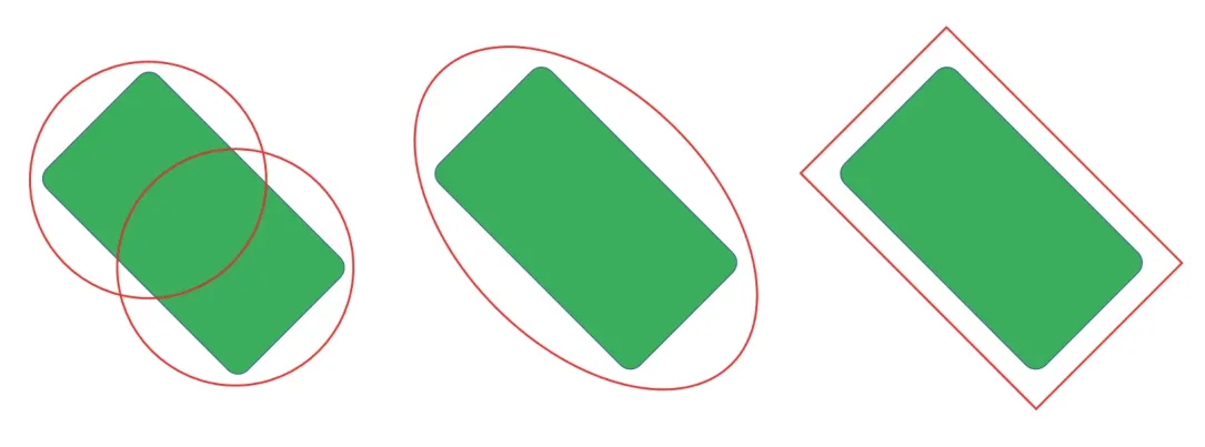
Fig.6.Candidate barrier shapes for collision avoidance.
In this article,we use two circular barriers as shown in the left of Fig.6.Each circular barrierh i(Xi),i=1,2 is defined by
where (xi,yi) denotes the center of each host circle with radiusriand (xT,yT) denotes the center of the target circle with radiusrT.Note that,the target vehicles may also be covered by multiple circles.In this example,we cover each vehicle with two circles,resulting in four circle-to-circle constraints to be satisfied ori=4.In this case,
for the front and rear circles respectively,whereLis the length of the vehicle.Using the two circle barrier leads to a mixed relative degree system(relative degree 1 w.r.t.steering and relative degree 2 w.r.t.acceleration).Therefore,we use filtered steering and the second order constraint equation shown in (17).Individual terms of the constraint can be calculated from (18).

Fig.7.Combined BF Intent Prediction and CBF Collision Avoidance System.
C.Control Barrier Function for Road Keeping
In general,the nominal controls will keep the vehicle in the desired lane.In some cases,in order to avoid a collision the vehicle may need to momentarily drive partially off the road.In order to minimize this necessary detour,a road keeping CBF is introduced.
wheree1is the perpendicular distance of the AV center from the road boundary,measured in a road-centric reference frame.In addition to the collision avoidance (CA) constraints(21),we implement soft road keeping constraints
wheresRKis a slack variable that softens the road keeping constraint.This is so that collision avoidance takes priority over road keeping.In practice,this tiered approach means the road keeping constraint can be violated to avoid a collision if necessary.The quadratic cost function (16) also has an additional term when using slacked road keeping constraints
whereHs>>Hδ,Hα.If the situation does not allow for a road keeping violation (e.g.,a concrete road barrier),this constraint can be made into a hard constraint (i.e.,moved into the same tier as collision avoidance).The CAS can then find the best possible course of action depending on which constraint violation causes less harm.However,this type of decision making is beyond the scope of this paper.
D.CAS Gating
We now present an approach that combines the intent prediction from Section III and the CAS from Section IV-B,to create a safety filter that can prevent unnecessary control interventions by the CAS.Fig.7 shows the system architecture.The nominal control may come from either a human or autonomous driver.The BF Intent Prediction System determines whether or not to activate the CAS.If the intent of either a target vehicle or the host is deemed to be dangerous,the gating boolean is set to true,otherwise it is false and the CAS constraint is deactivated for that target.The intent is determined by observing the value of 1st or 2nd order barrier constraints like (12) depending on the context and available sensing.The advantages of this system are shown in the example below.
E.Example
In this example,we compare CA with and without intent prediction for an AV driving along a route (Traver Road in Ann Arbor,M I),with a target vehicle approaching.In all cases below,the nominal controlsand α0are obtained using the controller from [25] and both the intent prediction system and CAS run at 20 Hz.
1) CA Without Intent Prediction:Without the context of the lane lines and ideal path for the target,it appears as though the target is approaching the AV and may collide with it.This leads to an evasive maneuver by the AV,as shown in Figs.8–10.Fig.8 shows the steering and throttle commands for the host vehicle.There is a large steering intervention by the CAS.Figs.9 and 10 shows the AV (blue) and target vehicle(red) at 0.5 s intervals.
2) CA With Intent Prediction (Safe Target):Next,we add the context of the lane lines and predict the intent of the target vehicle.If the target vehicle is approaching the road center and the constraintCfor the road center is violated,the gating boolean is set to true and the CBF CAS executes evasive action.Figs.11 and 12 shows that when the target is driving within its lane,the gating boolean is not activated and there is no evasive action.The figures show the AV and target vehicle at 0.5 s intervals.Note that the motion of the target vehicle is identical to the previous case.There is no intervention from the CAS in this case,andand α= α0throughout the simulation.

Fig.8.Section IV-E-1): AV Steering and Longitudinal Acceleration Commands.
3) CA With Intent Prediction (Dangerous Target):In this example,we show a case where the target vehicle deviates from its lane center and encroaches on the road boundary.The erratic behavior of the target could be due either to human error,a machine error/failure in case of a vehicle operating autonomously or semi-autonomously,or mode confusion(unclear to human and/or automated systemwho is responsible for control of the vehicle).In this example,the gating boolean is activated before the target crosses the lane boundary and the CBF CAS avoids the target.
Fig.13 shows the steering commands for the host vehicle and Fig.14 shows the evolution of the barrierh1(front circle to front circle barrier function) with and without gating.The evolution of the three other circle barriers has a similar shape.Note that the intervention by the CAS is later and sharper than without intent prediction.Note that the oscillations after the evasive maneuver come from the baseline controller.
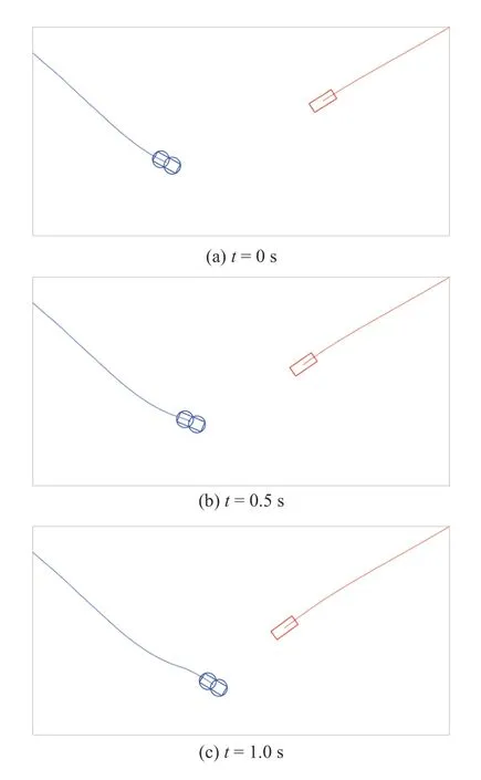
Fig.9.Section IV-E-1): Position of the AV and Target vehicle at 0.5 s intervals.
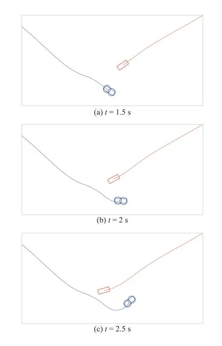
Fig.10.Section IV-E-1): Position of the AV and Target vehicle at 0.5 s intervals (continued).
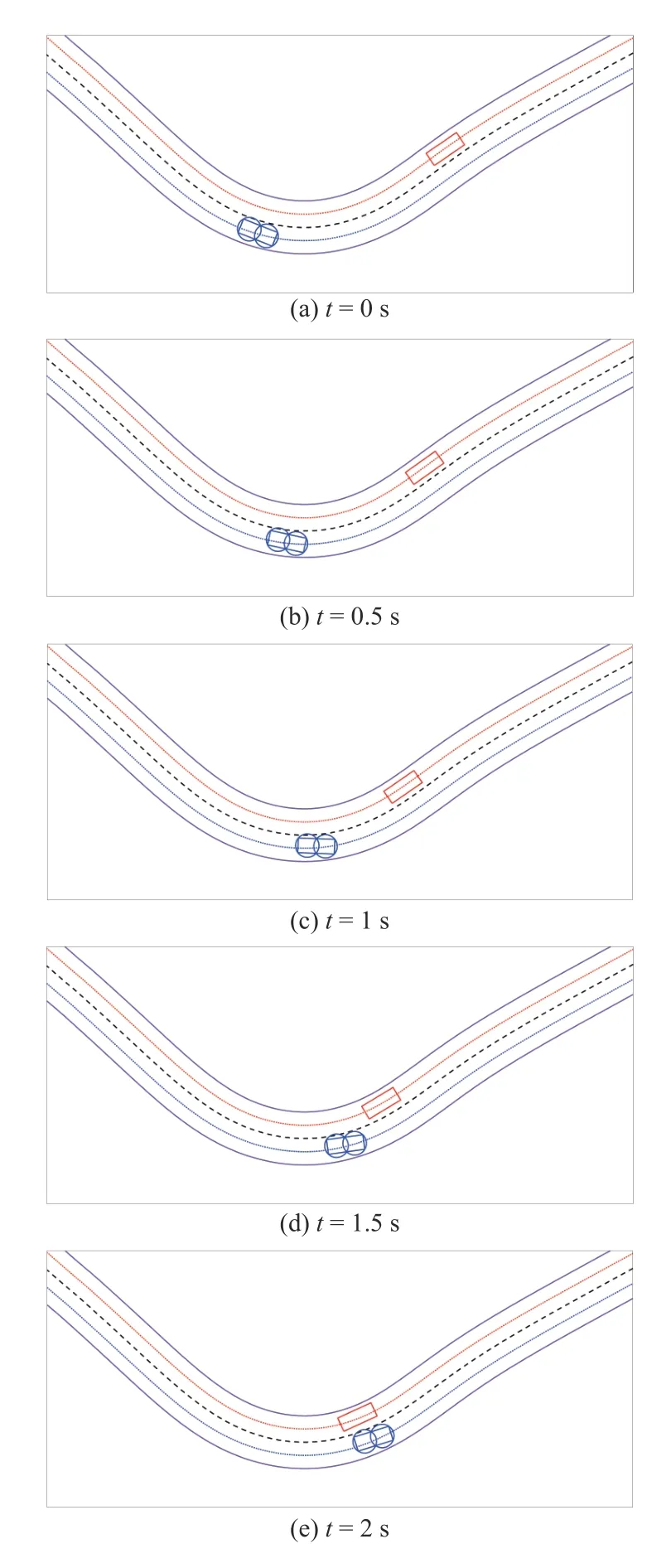
Fig.11.Section IV-E-2): Position of the AV and Target vehicle at 0.5 s intervals.
Fig.15 shows the lane deviatione1and Fig.16 shows the minimum distance between vehicles in meters with and without the BF gating.The deviation from the lane center is smaller when using the gating.The minimum distance between the vehicles does not drop below 0.8 m with the gating.Without the CAS the two vehicles collide as shown in Fig.16.Fig.17 shows the AV with BF gating and the target vehicle at 0.3 s intervals.
V.CONCLUSIONS
AVs and vehicles equipped with ADAS features can benefit from predicting the intent of nearby vehicles and using this information to plan their actions.If environmental context(e.g.,lane lines,intersection geometry) is available,it can be used to improve the performance of collision avoidance algorithms.This information must be used in a manner that does not greatly increase computational requirements,because the information is used to aid an existing vehicle control algorithm.We show how intent prediction can be used to create a less intrusive collision avoidance system,reducing unnecessary evasive maneuvers.
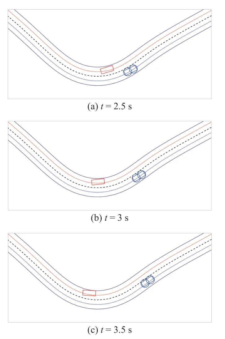
Fig.12.Section IV-E-2): Position of the AV and Target vehicle at 0.5 s intervals (continued).

Fig.13.Section IV-E-3): AV Steering Command.

Fig.14.Section IV-E-3): Circular Barrier Function.

Fig.15.Section IV-E-3): AV deviation from lane center.

Fig.16.Section IV-E-3): Minimum distance between vehicles.

Fig.17.Section IV-E-3): Position of the AV and Target vehicle at 0.3 s intervals.
杂志排行
IEEE/CAA Journal of Automatica Sinica的其它文章
- A Survey on Negative Transfer
- Three-Way Behavioral Decision Making With Hesitant Fuzzy Information Systems:Survey and Challenges
- Data-Driven Control of Distributed Event-Triggered Network Systems
- Distributed Nash Equilibrium Seeking for General Networked Games With Bounded Disturbances
- Position Measurement Based Slave Torque Feedback Control for Teleoperation Systems With Time-Varying Communication Delays
- Fixed-Time Stabilization of a Class of Strict-Feedback Nonlinear Systems via Dynamic Gain Feedback Control
