Electrospun carbon nanofibers for use in the capacitive desalination of water
2022-12-13BethwelTarusYusufuJandeKaroliNjau
Bethwel K Tarus, Yusufu A C Jande, Karoli N Njau
(1.Department of Materials and Energy Science and Engineering, Nelson Mandela African Institution of Science and Technology, Arusha, Tanzania;2.Department of Manufacturing, Industrial and Textile Engineering, Moi University, P.O Box, 3900, Eldoret, Kenya;3.Water Infrastructure and Sustainable Energy Futures (WISE-Futures) African Centre of Excellence, The Nelson Mandela African Institution of Science and Technology, Nelson Mandela Road, Tengeru, P.O.Box 9124, Nelson Mandela, Arusha, Tanzania;4.Department of Water and Environmental Science and Engineering, Nelson Mandela African Institution of Science and Technology, Arusha P.O.Box 447, Tanzania)
Abstract: Capacitive deionization (CDI) has rapidly become a promising approach for water desalination.The technique removes salt from water by applying an electric potential between two porous electrodes to cause adsorption of charged species on the electrode surfaces.The nature of CDI favors the use of nanostructured porous carbon materials with high specific surface areas and appropriate surface functional groups.Electrospun carbon nanofibers (CNFs) are ideal as they have a high specific surface area and surface characteristics for doping/grafting with electroactive agents.Compared with powdered materials, CNF electrodes are freestanding and don’t require binders that increase resistivity.CNFs with an appropriate distribution of mesopores and micropores have better desalination performance.Compositing CNFs with faradaic materials improve ion storage by adding pseudocapacitance to the electric double layer capacitance.The use of electrospun CNFs as electrodes for CDI is summarized with emphasis on the major precursor materials used in their preparation and structure modification, and their relations to the performance in salt electrosorption.
Key words: Capacitive deionization;Desalination;Carbon nanofibers;Electrospinning;Electrosorption
1 Introduction
Globally, there is a growing concern over the limited availability of freshwater.Many developing countries are facing severe shortages of freshwater that is important for domestic, agricultural and industrial use as well as good health of the populations[1].The demand for freshwater is estimated to increase at a rate of 1.8% per year[2]and by the year 2030, the demand is expected to exceed supply by approximately 40%[3].It is anticipated that the gap between demand and supply can be compensated for by producing water from the highly abundant saline and brackish waters through desalination.This approach is highly praised as a major solution to freshwater shortages in the world.The major desalination methods currently in use are reverse osmosis (RO), thermal distillation and electrodialysis, which account for about 59%,36% and 4% of global desalination capacity, respectively[4].These methods, however, are costly and energy-intensive, hence their applications especially in many developing countries are limited.Therefore,much effort is being directed towards cost-effective and energy-efficient technologies for the production of domestically, agriculturally and industrially usable water from nonconventional sources.
Capacitive deionization (CDI) is a relatively new desalination technique that is rapidly gaining interest particularly for the desalination of brackish water.It works based on the principles of electric double layers (electrosorption), intercalation of ions, and/or conversion reactions, by which feed water gets desalinated using a pair of electrodes to store opposite charges[5,6].The electrodes are regenerated through an ion desorption or deintercalation discharge step.The technique is quite robust, cost-effective, and energysaving for desalination of low to moderate salinity water.CDI removes the minor composition (salt) from water unlike the major methods such as RO which extract the major composition (water) from the saline feed.Additionally, the principle used potentially allows for energy recovery[7].Improvement of the performance of CDI has been focused on salt removal capacity and stability of the electrodes.The performance of the CDI process is generally dependent on the chemical, structural, and geometrical properties of the electrode materials[8,9].Suitable electrode materials should possess high specific surface area, suitable pore structure, appropriate surface chemical activity,high electrical conductivity, high wettability, excellent electrochemical stability and favorable ionic diffusion[10].Thus, electrodes have mainly been obtained from carbon materials or their composites[11].Carbon nanofibers (CNFs) are among the most promising electrode materials for electrochemical applications.They are of great significance due to their advantages of high chemical resistance, high strength per unit mass, and excellent thermal and electrical conductivity.These properties have enabled them to be used in catalysis, adsorption, energy storage, supercapacitors,or as reinforcements in high-performance composites[12,13].Importantly, the properties of CNFs can further be enhanced through surface modification to obtain high-capacity flexible electrodes having quick ion transfer paths, fast reaction kinetics and excellent cycling stability for electrochemical applications[5].Particular modification methods include doping with heteroatoms (Sulfur[14], phosphorus[15], nitrogen[16]etc.), coating/embedding with nanoparticles of metal sulfides[17], Prussian blue analogues[18]or metal oxides such as manganese oxides[19–21], titanium dioxide[22,23],zinc oxide[24,25]and introducing positively or negatively charged functional groups[26]into their structure.Proper tailoring of the CNF structure (multichannel,core-sheath, ribbon, etc.) and composition by modification results in exceptional desalination capacities and energy efficiency.
The technique of CNF fabrication primarily determines their structures and properties.It is a major route to tailor-made structure suitable for the intended applications.A well-known approach for direct CNF production is by vapor growth, where particular hydrocarbons are subjected to catalytic decomposition[27].Other methods that have been successfully applied include laser ablation and arc discharge[28].However, these methods have faced challenges in mass production due to costly equipment and low product yield[12,29].Nowadays, the popular carbon fiber production approach involves spinning to obtain fibers from a polymeric precursor followed by a controlled thermal treatment to convert them to carbon[30].Increasingly, the electrospinning technique is gaining a solid base in nanofiber fabrication due to its simplicity, versatility, robustness and the ease in controlling the functional properties of the end products[31].Using this technique, highly porous and incredibly lightweight nanofiber mats having a very high surface area and uniform morphology can be produced from a variety of materials[32].A major advantage of CNFs for use in CDI and related applications is that freestanding electrodes are obtainable without use of a binder.Most CDI electrode materials such as activated carbon are in powder form and require a slurry casting process.This involves the use of polymeric binders, which significantly alter the microstructure and reduces the conductivity[5,9,33].Herein,we review the use of electrospun CNFs as electrodes in CDI for water desalination in aspects of material selection and nanofiber modification.The review begins with elucidating the CDI process and CNF fabrication followed by discussion on the major precursor materials that have been used in the fabrication of CNFs by electrospinning.CNF structure modification methods and their impacts on desalination capacities are also summarized.Lastly, the prospect on the development of CNFs for use in CDI is presented.
2 Capacitive deionization
As an emerging water desalination technology,CDI has developed tremendously through rapid research in cell architectures, electrode structures, and mathematical modelling[34].The conventional CDI process is based on sorption of ions onto the surfaces of electrically charged porous carbon-based electrodes (Fig.1).
Normally, the setup of a CDI unit is composed of a pair of sufficiently porous electrodes with an electrically non-conductive spacer material between them.Feed water is passed through or between these two electrodes during the CDI process[7,35].In the electrosorption step, (Fig.1a), a cell voltage that ranges from 1 to 1.4 V is applied between the electrode pair as feed water is allowed to flow.The electric field generated causes ions present in the water to move towards the electrode surface having the opposite charge.The ions are then held electrostatically in an electrical double layer (EDL) which occurs at the electrode/water interface upon application of a cell voltage.In the desorption step (Fig.1b), the electrodes are discharged by reversing their polarity or shorting the supply so as to release the ions creating a stream of brine that flows out of the cell[34].CDI performance mainly relies on the geometry of the cell,the electrode material, composition of feed water and operating conditions[8,9].The geometry of CDI cells generally considers the electrode positioning and feed direction of water (flow-by or flow-through)[36].The flow-by setup is the most common one and involves passing the feed water between and parallel to the electrodes, where flow-through systems direct the feed water through the electrodes.The flow-by setup is slower in desalination since their operation is diffusion-limited.Flow-through setup is better with regard to desalination rates, capacities, and charge efficiencies due to its rapid adsorption kinetics and structurally compact cells[37].
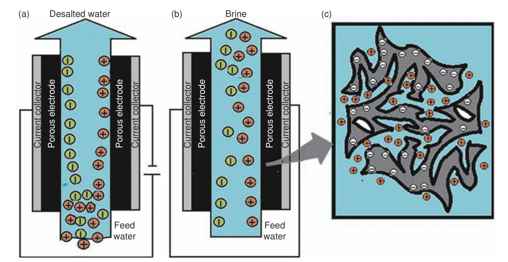
Fig.1 Conventional CDI setup: (a) electrosorption step, (b) desorption step and (c) electrosorption concept in materials[7]
The CDI process is cost-effective, energy-efficient and environmentally friendly.It requires low feed pressure and a low electric current that varies according to the size of the desalination unit as opposed to traditional techniques[5,38].It also allows for water desalination at ambient conditions.However, ion storage by the EDL mechanism is limited by the surface area of the electrodes, thus, it only works well with low salinity water[39].Other challenges such as anode oxidation and co-ion expulsion at the surfaces of the electrodes have rendered conventional CDI to perform poorly[36].To address these issues, ion exchange membranes and use of materials with Faradaic properties have been explored and have become the focus of current studies.Faradaic ion capture mechanisms(Fig.2) include reversible insertion/conversion reactions[40,41]or ion-redox active moiety interactions[42].Insertion/intercalation electrodes capture ions within interstitial sites of the electrodes, hence possess exceptional ion storage capabilities and selectivity due to the reversible nature of ion insertion[43].The majority of intercalation electrodes involve cation (Na+) insertion.Common materials that have been used include metal hexacyanometalates[44], and sodium transition metal oxides[45], etc.As for the conversion mechanism, reversible chemical transformations occur to form new compounds and predominantly involve anions (Cl–).Popular materials include BiOCl[41], Ag and AgCl[46].Ion-redox active moiety interaction mechanism is achieved with the use of particular polymers that possess redox active moieties within their chains.Anion or cation storage depends on the respective redox active moiety within a polymer.Material examples include polymers containing carbonyl groups such as polyimides which interact with Na+through redox reactions.Other examples are conducting polymers (p-type) such as polyaniline and polypyrrole,which capture and release Cl−when they undergo pdoping and dedoping respectively[6].Typically, a faradaic driven CDI process employs an asymmetric configuration where two electrodes are designed to be electrochemically different with a particular electrode exclusively targeting either cations or anions.
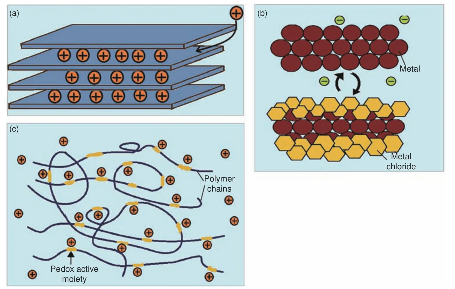
Fig.2 Faradaic ion storage mechanisms: (a) ion insertion/intercalation, (b) conversion reaction, and (c) ion-redox active moiety interaction[6,47]
3 Carbon nanofiber fabrication
CNFs have become of great importance to various industrial applications, thus, have attracted a lot of attention in material science studies.Their production techniques are of particular interest as they significantly influence their functional properties and suitability for particular applications[48].Currently, the most preferred approach for CNF fabrication involves nanofiber production from polymeric precursors followed by carbonization.Popular nanofiber production techniques include phase separation[49], self-assembly[50], interfacial polymerization[51], template synthesis[52], drawing[53]and electrospinning[31].CNFs may also be synthesized in a single-step catalytic vapor growth process such as chemical vapor deposition(CVD)[27].The factors considered in selection of a method to produce CNFs include the cost, fiber alignment, type of material, desired fiber structure and amount of fibers needed[54].
3.1 Polymer-derived carbon nanofibers
Advances in polymer technology and the ease of polymer processing have made polymer-derived CNFs accepted widely[54,55].With polymeric nanofibers, a dynamic system with variable pore sizes and shapes is developed[54].Table 1 highlights some of the major nanofiber fabrication methods from polymers.
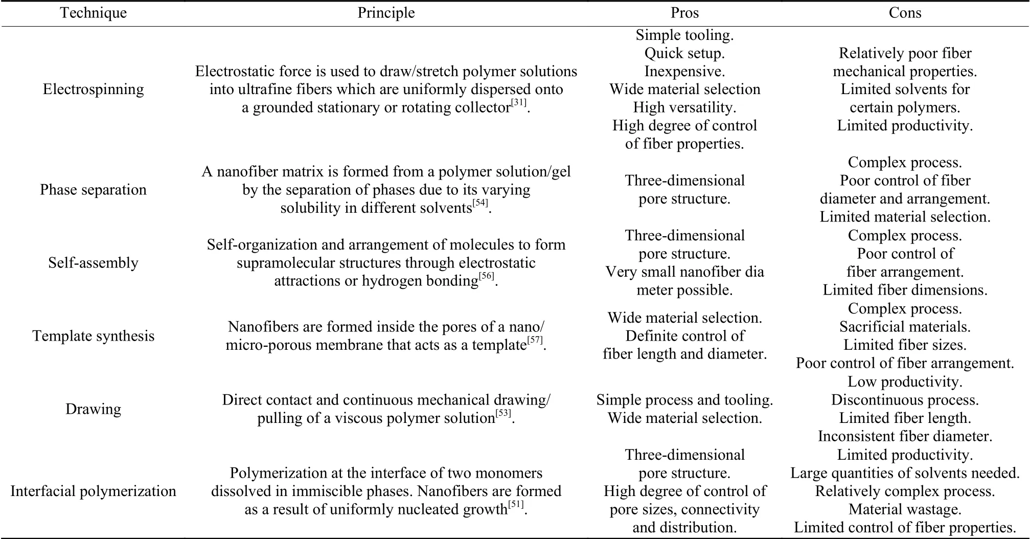
Table 1 A summary of polymeric nanofiber fabrication techniques
Polymer-based CNFs are usually fabricated by a combination of a nanofiber formation step from organic polymers with a thermal treatment process to stabilize the nanofibers in air followed by carbonization to convert them into carbon[30].Particularly, for nanofibers intended for CDI or related applications,physical or chemical activation is needed after carbonization to create additional pores[55].
3.2 Electrospun nanofibers
Among the nanofiber fabrication methods, electrospinning has become the most successful with regard to the simplicity of the process, the excellent properties of the resulting nanofibers and the diverse materials that can be used.Additionally, the technique has comparatively a high rate of production and is relatively of low cost[31].It is a very versatile process that allows for an incredibly high degree of control of the resultant morphologies and properties of nanofibers.It allows for the production of extremely lightweight and highly porous nanofiber mats having high surface area and uniform morphology[32].Electrospun nanofibers have been used in composite reinforcements, media filtration, enzyme immobilization,energy catalysis, sensing, tissue scaffolds, wound dressing, and drug delivery[31].In water treatment applications, electrospun nanofibers have gained some interests[58–62]but their potential is yet to be fully exploited with regard to material selection and types of additives used for structure modification and optimization[63].
3.2.1 Electrospinning process
The principle of fiber formation through electrospinning is generally similar to other polymeric fiber formation techniques by extrusion and drawing.However, there is a difference in how the fibers are drawn/stretched in electrospinning.Fiber stretching is achieved via an electrostatic repulsive force generated by applying a high voltage between the polymeric solution and a collector[64].A general setup for electrospinning (Fig.3) has the following components: a high voltage power supply for applying charge to the solution, a solution reservoir (commonly a syringe), a metallic capillary (spinneret) attached to the solution reservoir through which the solution is released, and a collector that is rotated for deposition of the nanofibers.For optimum control of the process, a pump is connected to regulate the polymer flow rate.Alternatively, polymer flow could be by its own weight.In such a setup, the solution reservoir is fixed vertically or tilted at an angle with the spinneret pointing downwards and the plunger is removed such that the solution exits under the force of gravity[65].Other configurations of the process that have gained popularity due to relatively high nanofiber production rates involveneedle-less setups which do not make use of spinnerets.Many commercial electrospinning installations are based on needle-less setups[66].
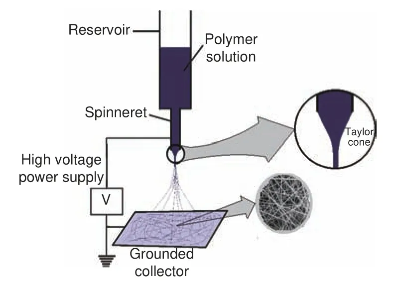
Fig.3 Basic electrospinning setup
Nanofiber formation by electrospinning generally occurs as follows.As the polymer solution emerges from the tip of spinneret, it forms a pendant droplet due to surface tension.Upon application of a high voltage, the polymer solution becomes charged such that a repulsive force is generated within the solution.This forces the polymer droplet at the tip of spinneret to distort into a conical shape (Taylor cone)[67].As the electric field is increased to reach a critical value, build-up of electrostatic force in the solution overcomes the solution surface tension,which results in the eruption and elongation of a jet from the polymer droplet towards the collector.The jet of polymer solution is stable closer to the tip of spinneret but then starts to undergo electrical instability (bending instability) whereby it whips out vigorously.The solvent evaporates from the solution jet as it stretches and accelerates away from the spinneret,leading to the collection of ultrafine fibers at the collector[31].Electrospun nanofiber morphology and nanostructure are influenced by solution properties,process settings and ambient conditions.Solution properties include surface tension, polymer concentration, solvent vapor pressure, viscosity, conductivity and dielectric constant[32,68].Solution viscosity is highly important as it significantly impacts nanofiber formation and fiber diameter sizes.Viscosity depends on polymer molecular weight and can be controlled by adjusting the solution concentration.Too low viscosity results in nanofibers containing beads, and as viscosity increases beads are gotten rid of and fiber diameter increases and becomes more uniform[69].The main process settings that should be considered include the voltage applied, feed rate, spinneret diameter and collection distance while ambient conditions that should be controlled are the temperature and relative humidity[70].
3.2.2 Stabilization and carbonization of electrospun nanofibers
After the fiber formation process, the next stage in CNF production is the stabilization process which is done to prevent thermoplastic polymers from melting and degrading during carbonization.Stabilization generally involves heating the nanofibers in air at conditions that are dictated by the type of polymer used.This process results in oxidation, dehydration, dehydrogenation, aromatic ladder formation, aromatization and/or crosslinking, which eventually determines the physical and mechanical properties of the resultant CNFs[30].Table 2 lists some of the general conditions used in the stabilization of popular polymer precursors.The degree of stabilization is largely dependent on the heating rate and duration of isothermal treatment at the stabilization temperature.It decreases with increasing heating rate and increases with increasing heating duration[71].Fast heating leads to incomplete chemical transition while the longer duration of isothermal treatment allows for adequate completion of stabilization.
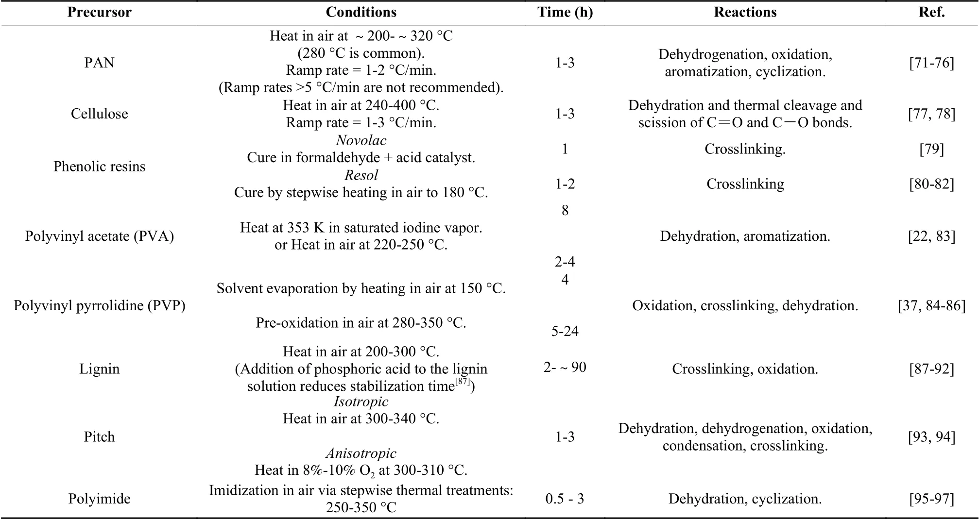
Table 2 Polymer stabilization conditions for common polymers
After stabilization, the carbonization process is then done in an inert environment at high temperatures (600-1 200 °C) that depend on the desired CNF properties[75].Carbonization conditions such as the carbonization temperature and time have marked effects on the carbon yield and the surface and electrochemical performance of electrospun CNFs.Carbon yields of polyacrylonitrile (PAN)-based CNFs increase with increasing the temperature.Carbon yields of about 84% and 89% are obtained by carbonization at 800 and 950 °C, respectively as a result of an increase in the amounts of volatiles released from nanofibers.On the other hand, CNF diameter decreaseswith increasing the carbonizing temperature while maximum specific surface area is attained at a moderate temperature of 850 °C[98].With regard to carbonization duration, a short carbonization time is preferred as it enhances attainment of mesoporosity due to low carbon densification[99].Fig.4 (a) and (b) show the optical images of CNFs.Fig.4 (c), (d) and (e) show SEM micrographs with corresponding diameter distributions of CNFs carbonized at 600, 800 and 1 000 °C[82].The mean fiber diameter decreases with increasing the carbonization temperature.
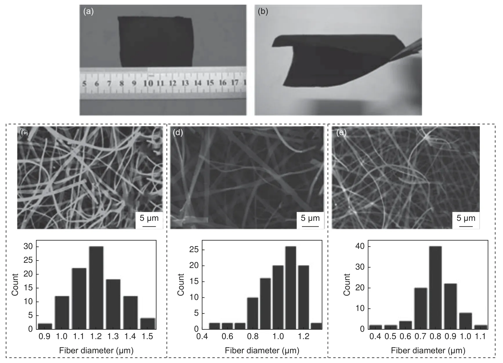
Fig.4 (a, b) Optical images of electrospun CNFs.(c) – (e) CNFs obtained at carbonization temperatures of 600, 800 and 1000 °C, respectively, with corresponding fiber diameter distributions[82].(Reproduced with permission from Elsevier)
4 CNFs as electrode materials in CDI
Suitable materials that can be selected as precursors for carbon fiber production should have a carbon backbone and be easy to process into fibrous form.Organic polymers are most suitable in this sense to produce easily controllable structures that have better electrochemical performance[11].As such, polymerbased CNFs have become major materials used in CDI as evidenced by the number of CDI/CNF-related studies done recently.From a quick search on Google Scholar, studies mentioning the use of electrospun CNFs in CDI account for approximately 10% of the total CDI studies done over the past 10 years.Various materials have been studied and an improvement in desalination performance has been consistently on an upward trajectory.Performance enhancement has mainly been gained by tailoring pore and surface characteristics[43].Fig.5 highlights the increasing trend of CNF-based CDI studies (from Google Scholar search)over the past 10 years.
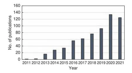
Fig.5 Number of publications on electrospun CNFs used in CDI per year between the years 2011 and 2021.(Google Scholar)
4.1 Popular electrospun CNF precursors
Commonly used CNF precursors include polyacrylonitrile (PAN), polyimides, phenolic resins,polyvinyl alcohol (PVA), pitch and polyacrylamides[100].Considering that the major CNF precursors are non-renewable, attention has been shifting towards materials from renewable sources such as cellulose and lignin[24].
4.1.1 Polyacrylonitrile (PAN)
As a CNF precursor, PAN has been the major material used in many studies to produce CDI electrodes.It is mainly preferred because of its relatively high carbon yield, good spinnability, good thermal stability, occurrence of nitrile polymerization to form stabilized products and the high strength of the resultant fibers[29].It is estimated that approximately 90% of carbon fibers produced globally are PAN-based[12].Still, the use of PAN homopolymer is said to hinder molecule chain alignment during the electrospinning process, leading to inferior quality CNFs[73].As well,CNFs from PAN require additional treatment in order to improve their surface area to be sufficient for CDI application.PAN-based CNFs with high specific surface area can be achieved by use of a polymer mixture of PAN with a pore-forming agent/sacrificial polymer that readily decomposes during carbonization[9,63].Porous CNFs based on blends of PAN with other polymers such as cellulose acetate (CA) have been studied with resulting electrodes having an interconnected 3-dimensional structure with a high surface area, high electrical conductivity and increased mesoporosity, which favors CDI application[99].Evidence from many studies has shown that the blend ratios and type of blending material have significant impacts on the electrochemical and desalination performance of PAN-based CNF electrodes.In PAN/CA blends, it has been demonstrated that the presence of CA does not significantly affect thermal decomposition of PAN, and leads to increased fiber yields[101].More importantly for CDI application, nanofiber diameter distribution for electrospun PAN-based blends has been shown to gradually increase as the additive polymer proportion is increased due to the increase in the solution viscosity as a result of the interactions between PAN and the additive polymer[99].Additionally, after carbonization, the CNFs exhibit a rougher surface and pores whose volume increases with increasing the additive polymer proportion[9].Ju et al.[99]reported a significant increase of up to 74% specific capacitance and over 56% increase in specific surface area due to blending PAN with CA, where CA was up to 20%.The blended CNFs had high mesoporosity, a property needed for excellent CDI performance, in contrast to the pure PAN-based CNFs which were mainly microporous.Electrochemical performance was relatively stable over time as its specific capacitance was observed to decrease by only 5% after 1 000 cycles at a current of 1 mA/cm2.
4.1.2 Cellulose
Cellulose and cellulose derivatives have also been shown to be very good precursors for the production of porous CNFs by electrospinning and subsequent carbonization and activation to produce CDI applicable CNF electrodes[102].Production of CNFs from CA has been demonstrated, where the carbonized nanofibers exhibited a graphite-like structure at a carbonization temperature of 1 500 °C.It was claimed that the unique structure gave the CNFs a range of attractive properties for many applications such as CDI[103].Studies on the structure of CNFs derived from electrospun CA and CA-based blends have shown that the CNFs exhibit a homogeneous structure with a high specific surface area, large pore volume and excellent electrochemical performance.Furthermore, the structure, properties and performance of the CNFs are readily tunable by controlling the polymer blend ratios, and the electrospinning and carbonization conditions[9,101,102].
4.1.3 Phenolic resins
Phenolic resins have been shown to have high carbon yield and high dimensional stability to produce high surface area CNFs[81].These phenolic resinbased CNFs have been shown to potentially offer outstanding properties for the improvement of performance in electrochemical applications[82,104].In a particular study, flexible phenolic resin-based porous CNFs were prepared by electrospinning, subsequent curing and carbonization to produce free-standing electrodes of excellent properties for CDI and supercapacitor applications.The non-linear structure of the resin,coupled with adequate control of solution properties during precursor preparation resulted in flattened nanofibers having sufficiently high specific surface area up to 855 m2/g without activation[81].Additionally,CNF networks gotten from electrospun phenolic resin have been shown to possess a robust structure with remarkable mechanical strength, flexibility, high surface area, conductivity, durability and reliability[82].Electrodes obtained from the CNFs show good cyclic stability and reach a desalination capacity of 50.1 mg/g at a cell voltage of 1.2 V with the feed water having a salt concentration of 2 000 mg/L.
4.1.4 Lignin
Lignin as an excellent precursor for CNF preparation has also been studied with promising results for CDI and supercapacitor applications.Song et al.[105],prepared and characterized electrospun lignin-based CNFs for CDI application and demonstrated that freestanding mesoporous electrodes could be formed,which had good desalination efficiencies up to 85.4%and capacitance up to 143 F/g.CNFs from ligninbased blends have also been described and their electrochemical performance has been evaluated.Recent work that blended lignin with polyvinylpyrrolidone(PVP) and zinc nitrate hexahydrate (ZNH) resulted in free-standing electrodes having a high specific surface area of up to 1 363 m2/g and a capacitance of 289 F/g.It was explained that the presence and proportion of ZNH were crucial to pore development and the specific surface area increase.ZNH presence in the precursor solution adjusted the viscosity and conductivity of solution during electrospinning, thus resulting in a significant reduction of fiber diameter from 209 to 83 nm[24].
5 Properties of CDI electrodes using carbon nanofibers
The key CNF properties that affect electrosorption capacity during desalination include the surface area, pore structure, pore-size distribution, pore accessibility, electrical conductivity and functional groups[106].The specific surface area of electrode materials is directly proportional to the number of available electrosorption sites and the EDL capacitance.Thus, the higher the surface area of CNFs, the better the electrosorption performance, especially when they possess appropriate pore size distribution[9].The difference in desalination performance among different kinds of electrodes is due to the different porous structures.Interconnected micro-mesoporous structures are favorable for quick ionic transportation[5,63].Ideally,the performance of the electrodes should not be significantly influenced by the operating conditions[107].For an EDL-driven CDI process, excellent performance and sufficient charge/discharge rates, are achievable when the CNF electrodes have a hierarchical porous structure with connected pores that facilitate electrosorption kinetics and easy diffusion of ions[9].The pores of electrode materials, which are classified into micropores (less than 2 nm), mesopores (2-50 nm)and macropores (greater than 50 nm), should be uniformly distributed for effective CDI application.Macropores act as the solution reservoirs while the mesopores as the channels for diffusion of ions and the micropores as the area for storage of ions[108].The presence and uniform distribution of interconnected micropores and mesopores are favorable for quick ionic adsorption on the electrodes and easy access to ions.An excess proportion of micropores allow for high charge accumulation (high capacitance) but presents a lot of resistance for charge diffusion, which delays the accessibility of ions by slow diffusion[74].The configuration of CNF electrodes in a CDI cell is also significantly important for the CDI performance.Water flow can be through or between the electrodes.One study demonstrated that when CNF electrodes were assembled into a flow-through CDI system, the desalination capacity and charge efficiency were 87% and 51% higher, respectively as compared with a flow-by system[5].The improvement in the CDI performance is attributed to full and fast contact between salt ions and the pores of the CNF electrodes in the flow-through setup.A high-speed flow-through setup has also been demonstrated where a desalination rate of 1.2 mg/g/min and a desalination capacity of 15.5 mg/g were observed using electrodes prepared from electrospun PVP-based CNFs encapsulated with TiO2.It was claimed that the combination of the advantageous properties of both TiO2-coated-CNFs and the flowthrough desalination architecture is a promising setup for industrial CDI desalination[37].Even though the flow-through configuration shows better performance,CNF electrodes need to be structurally robust and have adequate permeability for water to ensure efficient desalination.The electrical conductivity of CNFs increases with increasing the carbonization temperature.Chen et al.[82]observed that CNFs carbonized at 600 °C had a high electrical resistivity of ~52.95 Ωcm, while those carbonized at 1 000 °C had a resistivity of only 2.76 Ω cm.The increased electrical conductivity was attributed to the reduction of oxy-surface-groups at high temperatures.However, a balance between the electrical conductivity achievable and the pore structure of the CNFs is important since an extremely high carbonization temperature may result in high carbon densification[99], low porosity, elimination of functional groups, and aggregation of loaded active nanoparticles[109–111].Zhang et al.[109]summarized several approaches via which adequate electrical conductivity could be achieved by carbonization at low temperatures.These approaches include the use of catalysts to enhance the graphitization degree and embedding highly conductive materials such as carbon nanotubes or graphene in the CNF precursor.
6 Structure modification of CNFs
Varying the processing conditions of electrospun CNFs results in different structures that directly influence their desalination performance.Particularly, increasing the carbonization temperature of polymerbased nanofibers has negative effects on their pore properties and surface area[112].Further physical or chemical treatment to increase the porosity and specific surface area and to introduce redox active sites is needed for enhanced electrosorption[6,24,101,113,114].Major methods for improving CNF pore properties and surface area include physical and chemical activation,and pyrolysis of nanofibers fabricated from mixed precursors containing a thermally decomposable template[24].Grafting Faradaic substances is another way to enhance the surface properties of CNFs.
6.1 Pore-forming templates
The possibility to easily tune the properties of the electrospinning solution enables the adjustment of pore structures in CNFs by adding thermally degradable sacrificial agents/polymers[5,115].Pores are created in the nanofibers by phase separation of the sacrificial agents during the stabilization and removal of agents in carbonization.The difference between the solubility parameters of the host and sacrificial polymers determines the pore sizes[9,115].Using PAN as the host polymer and polymethylmethacrylate (PMMA)and polystyrene (PS) as the sacrificial polymers to fabricate micro-mesoporous CNFs, it was established that the porosity and specific capacitance of the resulting electrodes could be adequately tuned by varying the proportions of the sacrificial polymers[9].The use of PMMA resulted in a high performance electrode with a desalination capacity of 5.61 mg/g as compared with the use of PS (2.87 mg/g).The better performance is attributed to the uniform pore distribution and pore connectivity that are due to the complete decomposition of PMMA during carbonization.Fusion and reorganization of PS occurred, which resulted in nonuniform and blocked pores.Another study using a blend of PMMA with PAN to fabricate CNFs reported an increase of over 270% in specific capacitance where PMMA content was to 50% in the precursor solution.The authors explained that stabilization and carbonization of electrospun PAN/PMMA nanofibers resulted in the formation of multi-channel CNFs as a consequence of the different physicochemical properties of the component polymers and the complete decomposition of PMMA during carbonization[112].Other works using varying proportions of dimethyl sulfone (DMSO2) as a pore-forming agent to produce CNF electrodes with enhanced accessibility of the micropores reported a desalination capacity that was over 4.5 times higher than that without use of the agent[63].Because DMSO2sublimates readily at low temperatures, its use is cost-effective as it can easily be recovered and reused.Another pore-forming agent for PAN-based CNFs is PVP.The use of PVP yielded CNF electrodes that had quite high specific surface area and desalination capacity.A specific surface area of 1 232 m2/g and a specific capacitance of 202 F/g were reported for the PAN/PVP-based CNF electrodes[5].Fig.6 illustrates porous CNFs obtained from PAN/PMMA blends with increase in the proportion of PMMA.It is observed that the surface roughness of CNFs increases with increase in the PMMA content.
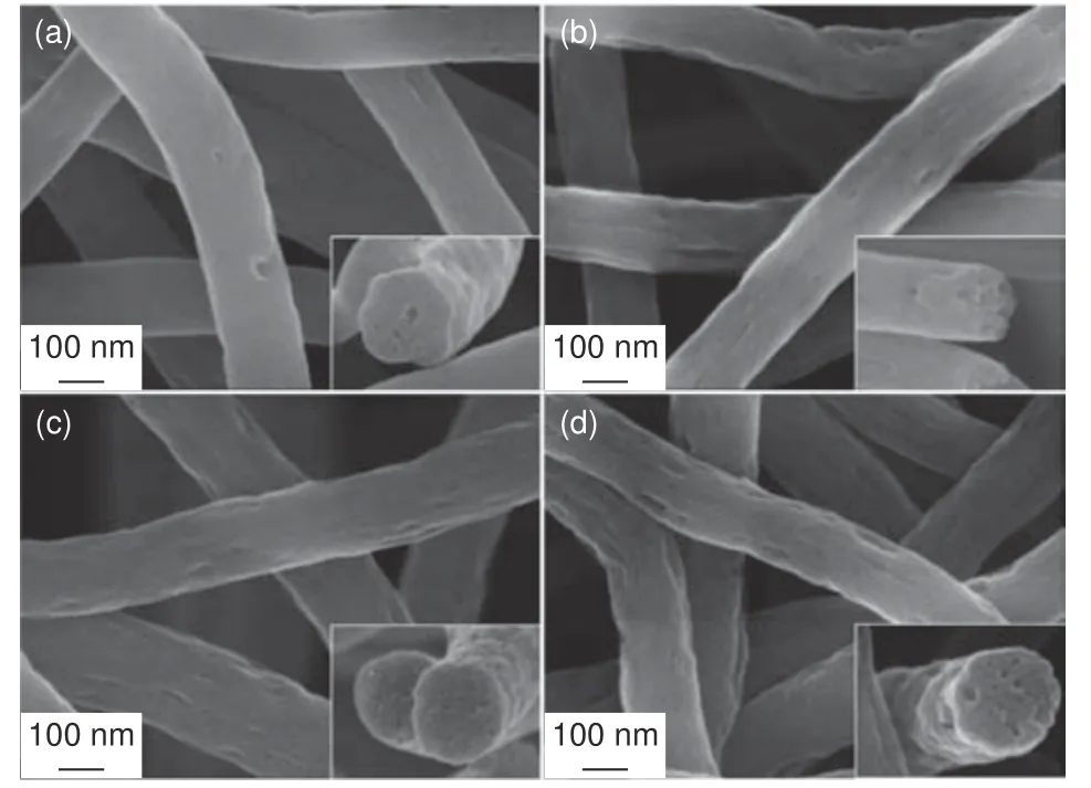
Fig.6 FE-SEM images of CNFs obtained from polymer blends with different PAN:PMMA ratios: (a) 90∶10, (b) 85∶15, (c) 80∶20 and(d) 75∶25[9].(Reproduced with permission from Elsevier)
6.2 CNF Activatio n
Activation has been the most preferred structure modification method due to its simplicity and relatively low cost.Activating agents and the process conditions have different impacts on the microstructure and properties of CNFs.The general approaches for activation can be physical or chemical.
6.2.1 Physical activation
Physical activation is usually carried out in a high temperature-controlled oxidizing environment at about 600-1 200 °C.Commonly used physical activating agents include carbon dioxide (CO2)[114]and steam[99].Pores are developed by oxidative reactions,and generation and evolution of gases.The activation temperature has a linear relation to the micropore volume[108].Activating with CO2gives more uniform pores in CNFs than with steam.Important parameters that affect the eventual performance of the resultant electrodes in CDI are the fiber diameter, activation temperature and activation time.It has been demonstrated that as the activation temperature is increased,the capacitance and electrosorption capacity of the CNFs also increase as observed by Wang et al.[114].When CO2is used as the activating agent, the electrode capacitance and desalination capacity increase by 33% and 69%, respectively, with increasing the activation temperature from 750 to 900 °C.At a higher carbonization temperature, a higher quantity of volatiles is released, resulting in more porosity and significant reduction in the fiber diameter[98].The influence of the nanofiber diameter has also been investigated and found that it significantly determines the development of pores during activation.Reports have shown that the smaller the fiber diameter, the larger the fiber surface, and the more significant the effects of the activation agent on pore volume and structure of CNFs[100].Tavanai et al.[100]prepared electrospun PAN at different solution concentrations to produce nanofibers with different diameters, which were carbonized at 600 °C and activated with CO2at 800, 850 and 900 °C.A 20% reduction in fiber diameter was reported after activation.The smaller the nanofiber diameter and the higher the activating temperature, the higher the specific surface area, total pore volume and weight loss.It was further explained that the pore characteristics could be tailored by adjusting the fiber diameter and activation temperature during electrospinning and activation, respectively.The activation time is also a significant parameter that influences the pore size distribution of CNFs.Increasing the activation time results in an increase in the mesopore volume and widening of existing micropores[116].Physical activation has relatively low yields and is carried out under high temperatures and lengthy activation times to produce CNFs with high micropore volume and low specific surface area[117].
6.2.2 Chemical activation
Chemical activation is performed with the help of a chemical agent.Reactions between the carbon and the agent occur at elevated temperatures for oxidative gasification of carbon to create pores[118].Main chemical activation agents include potassium hydroxide (KOH), nitric acid (HNO3), phosphoric acid(H3PO4), sodium hydroxide (NaOH) and zinc chloride (ZnCl2).Chemical activation is a less favored route because of costly chemicals, leaching of agents and the need for a washing process to remove residual activation chemicals.However, it has some advantages as it requires low temperature, short time and produces CNFs with relatively high carbon yield and high porosity[13,108,119].KOH is the most commonly used chemical activating agent for CNFs.The activation with KOH includes two steps.The initial step done at lower temperatures is normally a dehydration step and the second step is the activation step to develop pores at moderate temperatures.The effects of the temperature, time and fiber diameter on the surface properties of CNFs are expected to be similar to that in physical activation.However, findings against expectation have been reported.When KOH was used as an activating agent for PAN-based CNFs, the specific surface area increased with the activation time less than 30 min, beyond which the specific surface area decreased.The initial increase in the specific surface area was attributed to the reaction between KOH and carbon, resulting in formation of mesopores and micropores.When the activation time increased further,the pores were overly enlarged resulting in a decrease in the specific surface area[13].
6.3 Grafting/decorating CNFs with active agents
The maximum possible surface area improvement of CNFs through activation and templating is limited.Thus, loading high capacitance active agents/faradaic material such as metal oxides on the surfaces of CNFs has become an effective route to enhance the electrosorption performance[109].Electrospun CNFs are excellent substrates for supporting active agents for electrodes with enhanced electrochemical characteristics, outstanding electrical conductivity and selectivity in ion removal[120].Such electrodes are required in the CDI architectures such as rockingchair CDI[121], inverted CDI[26]and hybrid CDI[20].Generally, active agents are loaded on the nanofibers by adding soluble precursors or nanosized particles into the electrospinning solution.Uniform dispersion of these active materials on the nanofibers is crucial.Examples of agents to modify CNF electrodes’ structure,which have shown excellent performance in electrochemical applications, include cobalt (II, III)oxide[122], manganese dioxide[19], sodium manganese oxide[45], molybdenum disulfide[40], iron (II, III)oxide[123], titanium dioxide[37]and bismuth oxychloride[124].The outstanding properties of carbon-based electrode materials by modification agents have been described in many studies such as CNF composite containing boron and manganese dioxide for supercapacitor applications[21].The modified electrode materials have a mesoporous structure with remarkable surface area benefical for their applications in CDI.The functional groups usually provide electroactive sites and enhance the wettability, which result in reduced internal resistance to diffusion of charges and increased adsorption capacity.Fig.7 shows FESEM images of CNFs decorated with nanostructured bismuth oxychloride (BiOCl).Uniform but different morphologies of active agents were formed on the surface of CNFs by varying the dosages of the precursors during fabrication of hybrid materials[124].The formation mechanism of BiOCl nanoplates on the surface of the CNFs is still a subject needed for further study.But their formation mechanism for nanoflowers and nanospheres was reported to be due to their agglomeration when the amount of their precursor was increased.These unique structures result in outstanding electrochemical performance due to the numerous active sites for redox reactions.
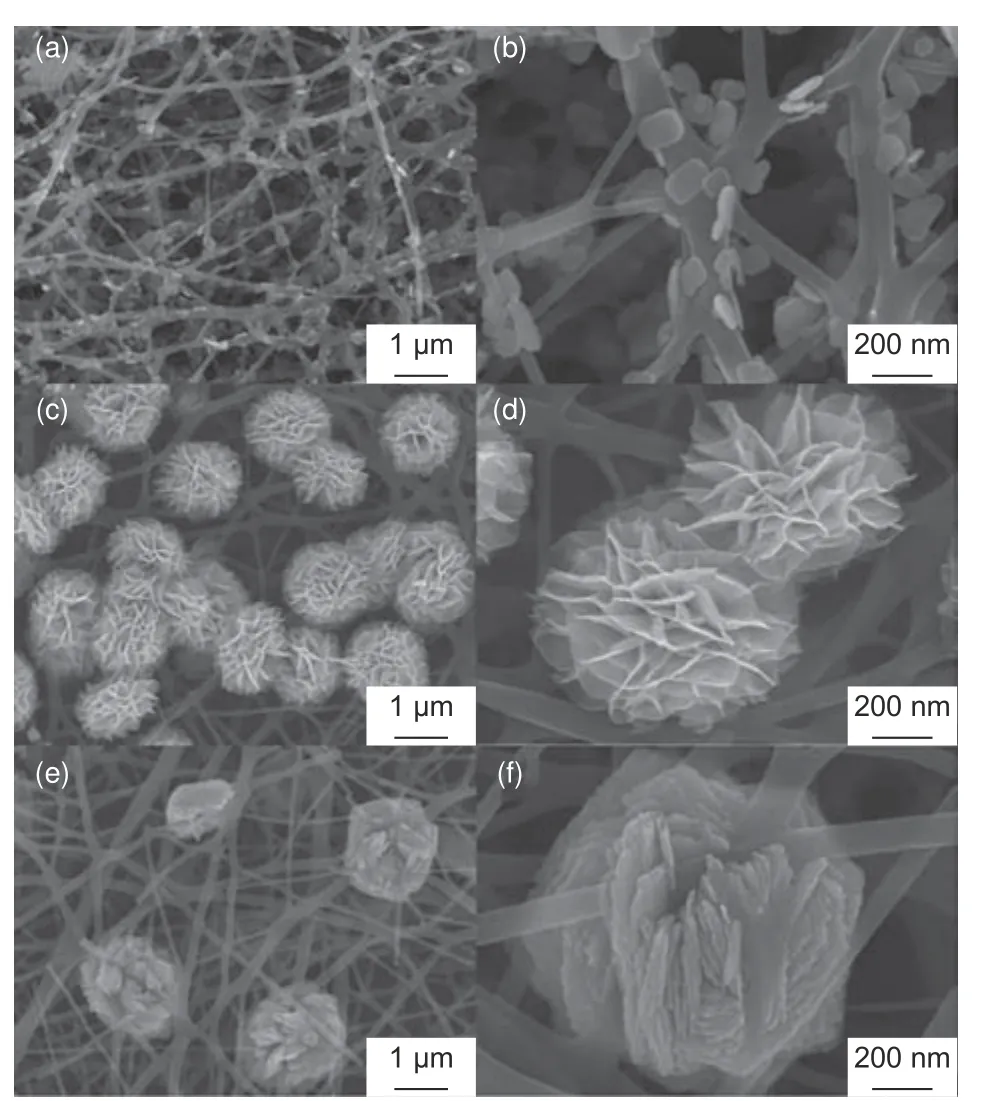
Fig.7 FE-SEM images of BiOCl-CNF hybrid 3D networks: (a-b) nanoplates, (c-d) nanoflowers, and (e-f) dense nanospheres formed on CNFs at low, moderate and high precursor dosages, respectively[124].(Reproduced with permission from Elsevier)
A 3D framework of PAN-based CNFs loaded with porous carbon polyhedra (PCP) derived from metal organic frameworks (MOFs) (Fig.8) has been reported to possess a highly porous structure with numerous channels allowing easy ionic diffusion and access[125], which has excellent desalination performance, exceeding those of individual CNFs and PCP.
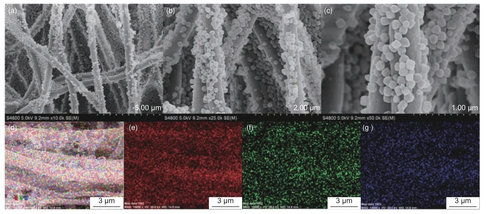
Fig.8 (a – c) FE-SEM images of CNFs modified with MOF-derived PCP at different magnifications and the EDS elemental mapping images of (d) CNF-PCP,(e) C, (f) N, and (g) O[125].(Reproduced under CC-BY 4.0)
CNF-based faradaic electrodes expectedly exhibit lower specific surface area than pristine CNFs or other hierarchically structured pure carbon-based electrodes but possess significantly higher electrochemical performance.It has been shown that the surface area decreases with increasing the amount of the additive agents that are mostly non-porous[20,122].Cobalt(II, III) oxide nanoparticles and carbon nanotubes have been decorated onto hollow electrospun CNFs to fabricate three-dimensional flexible hierarchical composite CNF electrodes.The undecorated CNF mats had a specific surface area of 432.3 m2/g while CNF mats decorated with carbon nanotubes and cobalt (II,III) oxide had a much lower specific surface area of 320.8 m2/g.However, the decorated CNFs showed a specific capacitance of up to 425 F/g while the higher surface area CNFs had a lower capacitance of only 214 F/g.It was claimed that the unique structure of the hollow electrospun CNFs enhanced total infiltration and provided sufficient surface area to accommodate the electroactive sites from the embedded cobalt (II, III) oxide nanoparticles.The structure of the composite electrode enabled excellent conductivity and shortened diffusion length for the targeted ions,resulting in a CDI system that had an adsorption capacity of 58.6 mg/g for a 1 500 mg/L NaCl solution at a rate of 12.27 mg/g/min under at a cell potential of 1.4 V[122].
7 Performance of CNFs versus other electrode materials in CDI
Since the first use of electrospun CNFs in electrochemical applications, their performance has continually improved and even outperformed other carbon-based electrode materials such as carbon aerogel and graphene as shown in Table 3.Outstanding electrosorption performance of CNFs has particularly been seen when they are composited with faradaic materials.Purely micro-mesoporous structured CNFs rely only on the EDL mechanism for salt removal.EDL-based desalination performance is highly limited due to the reliance on the available specific surface area whose access sharply decreases under high current density[24].Composites/hybrids of CNFs with pseudocapacitive materials produce electrodes that have improved performance as highlighted in some of the previous sections.Outstandingly high capacitance and salt removal capacities at high rates are achieved through the synergistic effects of electrostatic adsorption, surface redox reactions and intercalation of ions[6].Fig.9 and 10 shows the various electrochemical and desalination performance curves of CNF-based electrodes, respectively.
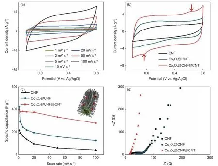
Fig.9 Representation of (a) CV curves at different scan rates of modified CNF electrodes.(b) Comparison of CV curves of pure CNFs with the surface-modified CNFs.(c) Comparison of specific capacitance of CNFs with the surface-modified CNFs at different scan rates (inset: schematic illustration of rapid ion transport mechanism of surface-modified CNF electrode).(d) Nyquist plots of pristine CNF and surface-modified CNF electrodes[122].(Reproduced with permission from Elsevier)
Other than the CNF-based electrode properties,various system-specific parameters affect the electrosorption performance.These include mode of operation, applied voltages and current, feed flowrates and feed salt concentrations[7,34,38,39].Table 3 compares electrochemical and desalination performance of CNF-based electrodes with other materials.
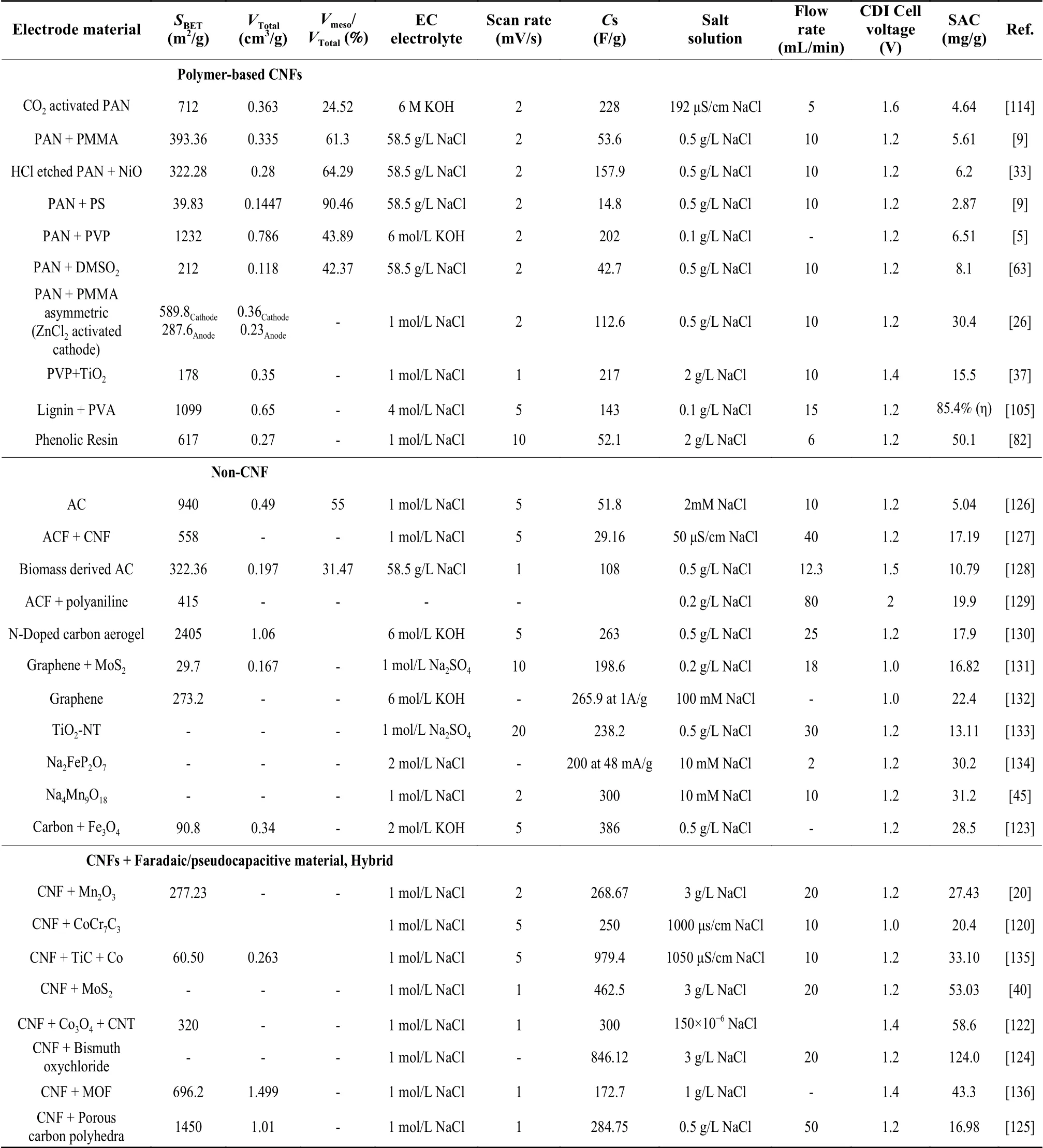
Table 3 A comparison of properties and electrosorption performance of electrospun CNFs with other materials
8 Summary
The development of CDI as a potentially inexpensive water desalination technology is rapidly being realized owing to the effort of many studies on electrode materials that possess remarkably high electrochemical performance.Electrospun CNFs are excellent electrode materials that are well adaptable to any of the ion capture mechanisms and CDI configurations due to their unique properties, simple fabrication route and easily modifiable surface characteristics.For optimized application, the CNFs structure should be adequately controlled and adapted to requirements.Essential electrode characteristics re-quired for reasonable salt removal capacities by CDI include high electrical conductivity, high surface area,large pore volume, high capacitance, high hydrophilicity, appropriate surface chemistry and crystal structure, excellent electrochemical stability, and a welldeveloped hierarchical pore structure with interconnected pores ranging between micropores and mesopores to facilitate quick ionic transfer, fast redox reaction kinetics and excellent cycling stabilities.Pristine CNFs possess a highly microporous structure which limits the utilization of their available surface area during electrochemical applications.The CNF fabrication process should offer many opportunities for tailoring functional properties.As a major nanofiber production method, the electrospinning process is a key factor in the modification of CNF properties through adjustments of the precursor solution properties and introduction of suitable additives that decompose during carbonization to form pores or as active agents contributing to ion storage in a CDI cell.Also, the various activation and surface treatment approaches significantly contribute to the enhancement of CNF properties to attain high desalination capacities.
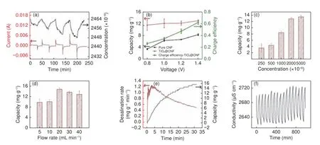
Fig.10 Desalination performance of CNF electrodes containing TiO2 as an active agent: (a) electrosorption curves in 2 500 mg/L NaCl feed at various cell voltages, (b) salt removal capacities and charge efficiencies at varying voltages, (c) salt removal capacities at varying feed concentrations, (d) salt removal capacities at varying flowrates, (e) salt removal capacity and rate versus time during cycling, (f) cycling stability of the electrodes[37].(Reproduced with permission from Elsevier)
In order to realize successful use of CNFs in CDI, particular challenges that need to be addressed include the limited varieties of precursor materials,energy utilization, and economic and environmentally-friendly fabrication of CNFs.In general, substantial improvements in CDI are still expected to be seen through compositing approaches that take advantage of the flexibility of the electrospinning process[24]and decorating microporous CNF surfaces to increase CDI capacity and kinetics[122].Decreasing CNF diameter is one route that could be further explored to improve the performance of hierarchically structured CNFbased electrodes for electrochemical applications.Reducing CNF diameter by intensified drawing and enhanced thermal shrinkage has been shown to result in electrodes with excellent specific capacitance and low relaxation time during charge diffusion[24].The precisely controlled and unique attributes of electrospun CNFs obtained from innovative precursors shall continue to be exploited in the development of advanced and optimized electrodes tailored for specific ion removal.Target ion properties are the main guide for optimum electrode design.Such electrodes have been shown to reach remarkable desalination capacities(>100 mg/g) through the synergistic effects of different ion capture mechanisms that combine two or more of the following: electric double layers, conversion reactions, ion intercalation reactions, and ion-redox active moiety interactions[6].Thus, application of CDI at the industry level should be realizable especially with the use of innovative pseudocapacitive nanocomposite CNF electrodes whose ion storage capacity is not determined just by the available surface but by their entire structure.It is worth noting that the use of pseudocapacitive materials with CNFs in CDI electrodes is still in its infancy.Therefore, there is still much to be done with regard to further understanding their different mechanisms, environmental impacts,and long-term material behavior among other practical implementation challenges.
The major challenges that still plague the application of electrospun CNFs are their relatively low mechanical strength, low productivity and expensive precursor materials.Industrial-scale production of CNFs through electrospinning faces a lot of economic and environmental challenges primarily due to the use of the highly expensive PAN and the large amounts of costly and toxic solvents.Recovery attempts of used solvents come with additional challenges, which further escalate production costs.Technically, the productivity of electrospun nanofibers has been improved significantly through electrospinning configurations that can easily be scaled up such as needleless setups.However, production scale-up is at the expense of critical fiber properties such as fiber uniformity and size which are easily monitored through the conventional and easily optimizable single-needle setups.Multi-needle setups should result in increased productivity, but still have issues related to fiber quality, electrostatic repulsions generated among neighboring jets, and large production space requirements for the high number of spinnerets needed[54].Presently, many industrial-scale electrospinning devices (needle and needleless) have been developed and are commercially available depicting the immense advancements made.Nonetheless, a technoeconomic analysis of electrospun CNF production in relation to intended applications needs to be carried out.With regard to precursor alternatives for PAN,significant advances have been observed through many studies that have focused on different materials.For instance, highly abundant alternatives such as cellulose and lignin have been shown to be potential replacements for the purely synthetic polymers.And even though the lengthy processing routes for these renewable materials impacts their acceptance, they are gradually becoming mainstream CNF precursors.An important area that still needs more attention in alternative CNF precursors is development of comprehensive material stabilization schemes prior to carbonization.Regarding CNF mechanical properties, some of the strategies that have been put forward for their improvement[137,138]have sufficed, but the influences of structure modification at high temperatures and property enhancement post-treatments need to be considered.For example, introducing multi-sized pores in the CNF structure may significantly reduce mechanical strength.Embedding inorganic nanoparticles (faradaic) into the nanofibers should enhance mechanical properties, but, upon further processing, these properties could be diminished because the bond between the polymer matrix and the nanoparticles may be disrupted at the high temperatures of carbonization.Further focused investigations could yield a better understanding of the interactions between the CNF structure and specific nanoparticle additives or post-treatment modification in relation to mechanical properties and application conditions.
Acknowledgements
This work was carried out with the financial support of the ICIPE – World Bank Financing Agreement No.D347-3A and the World Bank – Korea Trust Fund Agreement No.TF0A8639 for the PASET Regional Scholarship and Innovation Fund.
Conflict of interest
The authors declare no conflict of interest.
杂志排行
新型炭材料的其它文章
- Coal-based graphene as a promoter of TiO2 catalytic activity for the photocatalytic degradation of organic dyes
- 咖啡渣成型制备生物质炭及其CH4/N2分离性能
- A flexible hard carbon microsphere/MXene film as a high-performance anode for sodium-ion storage
- Preparation and lithium storage of anthracite-based graphite anode materials
- Oxygen-incorporated carbon nitride porous nanosheets for highly efficient photoelectrocatalytic CO2 reduction to formate
- 炭纸衬底上化学气相沉积直立型二维过渡金属硫化物及其电催化产氢性能
