Research on Key Technologies of Segmented Solid Rocket Booster
2022-10-29LUHejianCHENHongZHAOYujingMIAOZhiwenLISiheng
LU Hejian ,CHEN Hong ,ZHAO Yujing ,MIAO Zhiwen ,LI Siheng
1 Xi’an Aerospace Propulsion Institute,Xi’an 710100
2 Aerospace System Engineering Shanghai,Shanghai 201108
Abstract: The research status on the development of large segmented solid boosters is introduced,showing that the key technologies of the motor have now been acquired and meet the operational requirements of the rocket,which may provide a reference for subsequent development of large segmented solid booster motors and their application in space launchers with solid strap-on boosters.
Key words: segmented solid motor,key technology,solid booster,space launcher
1 INTRODUCTION
Main schemes of commercial space launchers with strap-on boosters are based on a central liquid propelled core stage with additional strap-on solid boosters,so making full use of the advantages of both liquid and solid propulsion systems.Compared with liquid boosters,solid rocket boosters possess the advantages of large thrust at take off,high reliability,simple structure and low cost,which make them the preferred options for strapon space launchers.
A segmented solid motor means that the combustion chamber is divided into several sections.Each section of the chamber is insulated and loaded with propellant independently,and then joined and assembled to form a complete combustion chamber.The purpose of using a segmented combustion chamber for a large solid motor is to take advantages of the current small development capacity to realize the development and production of a large motor,thus reducing the difficulty and cost of the development of a large solid motor.
The segmented solid motor has unique advantages in the application of medium and large boosters,and is the main form of propulsive system for foreign space launchers,such as the American Space Shuttle,the Ares series rocket,Europe’s Ariane 5,Japan’s H-2B,India’s PSLV,GSLV-MK3 rocket,all use segmented solid motors as boosters.
It was the first time for segmented solid boosters to be used on space launchers in China.So it was necessary to develop various key technologies including the segment joining of large segmented solid motors,flow stability,strap-on and joining technology of a solid motor with a liquid core stage,and manage the thrust imbalance control between solid motors pairs thus realizing a fully engineered solution.The research approach for the above key technologies is introduced in this paper.
2 JOINING TECHNOLOGY OF SEGMENTED SOLID MOTOR
The joining technology of segmented solid motors includes the design and analysis of the sealing structure of the segmented chamber case and insulation structure of segmented chamber.The sealing structure at the joint of the segmented chamber case impacts the assembly process,load bearing capacity and sealing performance of the shell,and the insulation of the segmented chamber affects the assembly process and insulation reliability of the chamber during the operation.
2.1 Joining and Sealing Technology of Segmented Motor Case
The joining structure of the segmented motor case adopts U-shaped structural parts and radial pins,with sealing in the form of three sealing rings,thus guaranteeing operation reliability of a large-sized segmented motor case,shown as Figure 1.

Figure 1 Joining and sealing structure of “U” type and radial pin
2.1.1 Simulation analysis of segmented joining structure
A three-dimensional finite element model (FEM) of the segmented case joining structure was established (see Figure 2),and analyzed with an applied stress,internal pressure of 8.5 MPa,to obtain key parameters such as the deformation and stress distribution of the joining structure,thus ensuring that the segmented case joining structure can meet the requirements of strength,sealing and repeatable assembly needed to meet the internal pressure load of the motor.
The stress and deformation of the case joining structure is shown in Figures 3-5.The maximum Mises stress values of the case cylindrical section,the front U-shaped part and the aft U-shaped part were 1057 MPa,950 MPa and 868.9 MPa respectively,and the maximum stress positions of the front and aft U-shaped parts were found to be at the edge of the pin hole.The calculation result shows that the structural strength,rigidity and deformation of the sealing structure of the segmented case joining meets the design requirements.
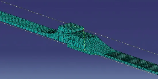
Figure 2 FEM of segmented case joining structure
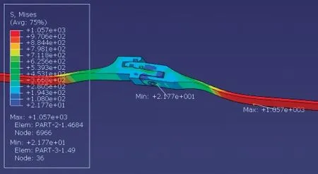
Figure 3 Stress and deformation of “U” type parts

Figure 4 Stress and deformation of front “U” type parts
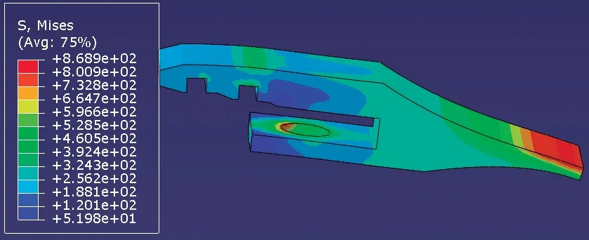
Figure 5 Stress and deformation of aft “U” type parts
2.1.2 Test verification of segmented joining and sealing technology
The motor case completed 8.7 MPa internal pressure test(see Figure 6).The measured maximum strain and calculated stress values are shown in Table 1.It can be seen that the maximum Mises stress value of the case is 1121.9 MPa,whichis basically equal to the maximum Mises stress value under the same internal pressure calculated by the finite element analysis,i.e.1094.3 MPa.

Figure 6 Internal pressure test of segmented motor case

Table 1 Maximum strain and stress data of case under internal pressure
It can be seen from the measured strain data that there is no plastic deformation of the segmented motor case.After the test,the case is taken apart,and the appearance of the pin and the sealing ring was in good condition,which verifies that the connection of the U-shaped structural parts and sealing structure are of reasonable design and the sealing is reliable.
2.2 Insulation Joining Technology of Segmented Combustion Chamber
The impact analysis of the thermal insulation structure at the joints of the segmented combustion chamber on the molding process,thermal insulation reliability,grain structural integrity,and joining assembly feasibility was conducted.By comparison of various joining schemes of the thermal insulation structure,a pressure-actuated joining structure with a specific opening angle(see Figure 7) was adopted,thus ensuring that the front and aft thermal insulation structures in this area are in a state of interference fit during operation so as to improve thermal insulation reliability.

Figure 7 Insulation joining structure at segmented position of combustion chamber
2.2.1 Simulation analysis of the insulation structure at the segmented joint of combustion chamber
A certain amount of interference is designed at the joining structure of the thermal insulation,which is subjected to a certain degree of extrusion deformation during the joining process of the combustion chamber.Therefore,a three-dimensional finite element model was established for the insulation structure to analyze the deformation and stress of the insulation structure during the joining process of the chamber.The calculation results are shown in Figure 8 and Figure 9.
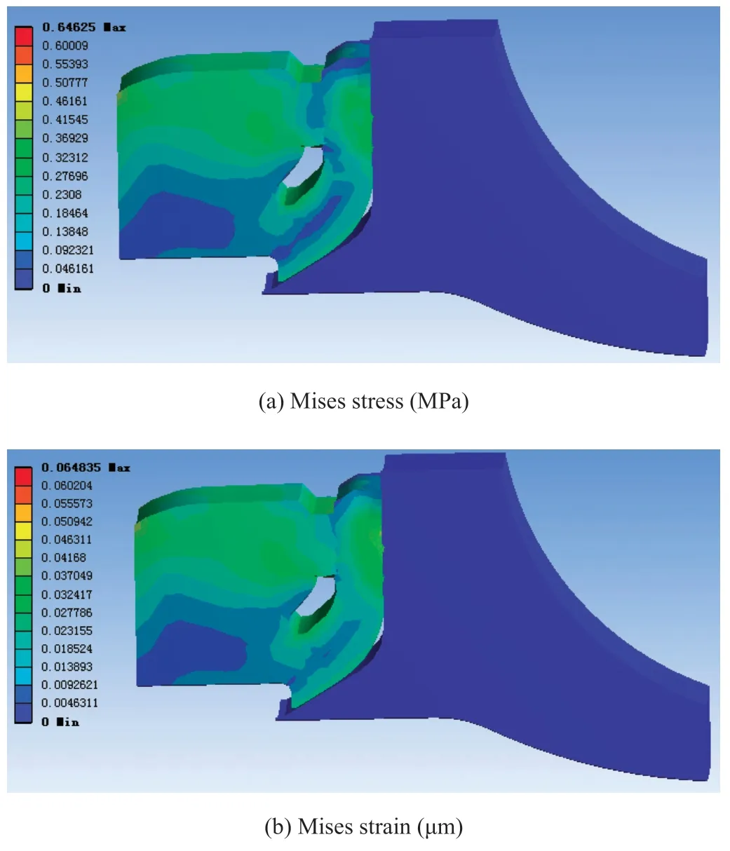
Figure 8 Stress analysis of “J” type parts in process of joining with combustion chamber
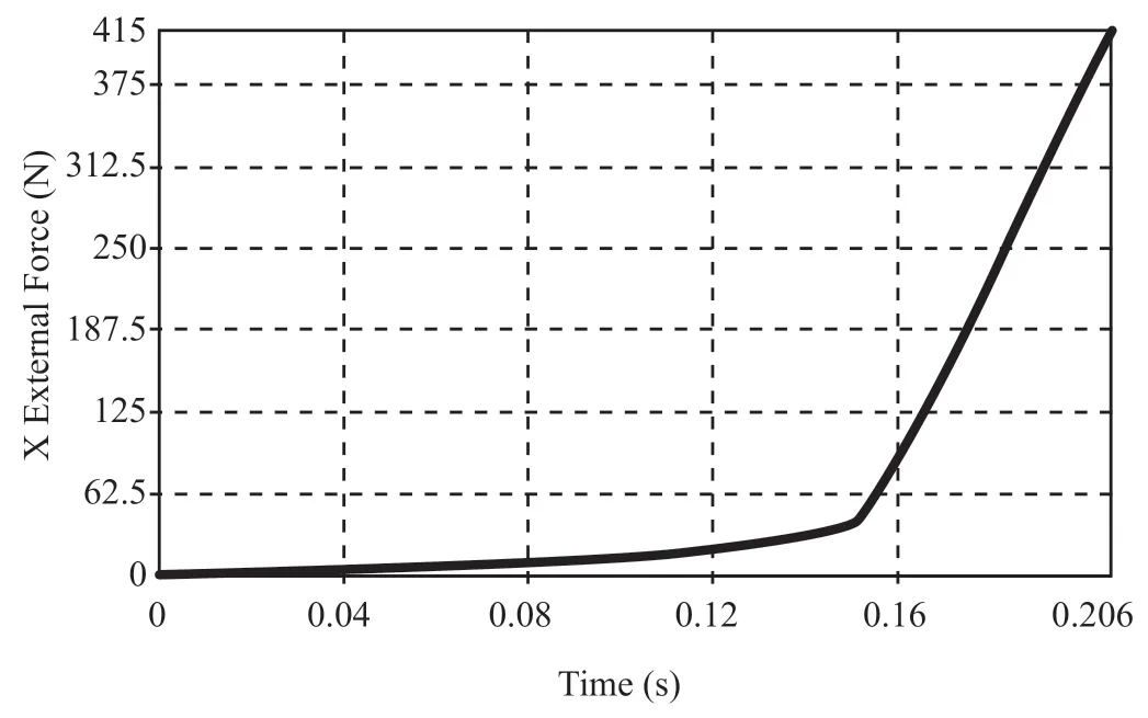
Figure 9 Normal stress at contact surface of “J”type parts in the process of joining with combustion chamber
According to the deformation,stress,and maximum normal stress at the contact surface of the thermal insulation structure,a reasonable design value for expansion angle and interference of the thermal insulation structure can be determined so as to ensure that the reaction force generated by the deformation of the thermal insulation structure does not affect the assembly process and structural integrity of the thermal insulation.
2.2.2 Test verification of insulation joining technology of segmented combustion chamber
Research on the different splicing methods and curing process of the segmented insulation structure were completed,and the annular splicing method was optimized.An internal quality inspection method of the thermal insulation structure was proposed to ensure the bonding and forming quality of each splicing interface of the thermal insulation structure was sufficient.
After the test,the segmented solid motor chamber was disassembled,and the insulation structure at the segmented position was confirmed to be in good condition (see Figure 10).There was no debonding or burn-through at each splicing and bonding area,which confirmed the design and forming process of the insulation joining structure are reasonable.

Figure 10 “J” type insulation structure at the segmented position after test
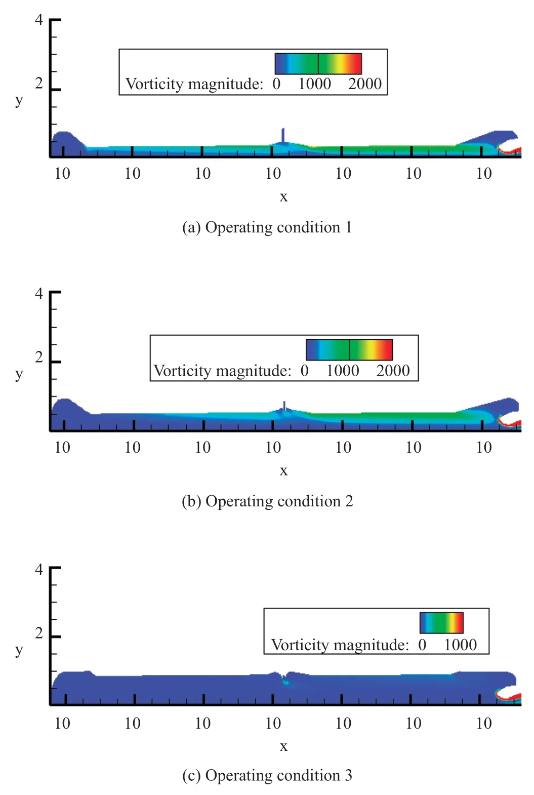
Figure 11 Vortex magnitude distribution in flow field of segmented combustion chamber (0-1000 1/s)
Following the disassembly of various motors after static firing test,it shows that the segmented joining technology meets the requirements for use.
3 FLOW STABILITY TECHNOLOGY OF SEGMENTED SOLID MOTOR
The segmented solid combustion chamber has the characteristics of large L/D ratio,complex grain configuration,submerged nozzle,and a design providing a grain gap at the segmented position,and inhibiting structure at the grain end.The gas flow inside the chamber may be effected due to obstacle vortex shedding,surface vortex shedding and corner vortex shedding,which may induce a combustion instability phenomenon resulting in pressure oscillation thus affect the performance and reliability of the motor.For this reason in the development process of launchers like Titan,the Space Shuttle,Ariane and Ares,designers have carried out a lot of research work on flow stability analysis of segmented solid motors.
3.1 Simulation Analysis on Flow Stability of Segmented Solid Motor
Using cold flow particle image velocemetry (PIV) technology and high-speed motion analysis technology,cold flow experiments were carried out on the effects of segmented joining slitsize as well as the height of inhibitor at the end face of segmented grain in the gas channel on the flow field of the segmented solid motor.The internal pressure,velocity distribution,vortex generation and shedding in the combustion chamber of the segmented solid motor were analyzed.The research considering the influence law of the change of the main design parameters of the segmented solid motor on the internal flow characteristics was completed,and numerical simulation analysis of the internal flow field was completed.
Using large eddy simulation technology,acoustic-vortex coupling simulation analysis of the flow field in the combustion chamber of the segmented solid motor under three typical operating conditions was completed.Calculation results showed that there were no obvious surface vortex shedding phenomenon,and no obstacle-type vortex shedding induced by the inhibiting insulation layer on the end face of the segmented grain joint area,and the design of the combustion chamber met the requirements for flow stability.
3.2 Test Verification of Flow Stability Technology of Segmented Solid Motor
According to three typical moments calculated under the flow field simulation,the measured pressure data of the segmented solid motor was analyzed (see Figure 12),and it could be seen that there was no pressure oscillation during motor operation,which verified that a stable internal flow field can be realized through structural optimization of the segmented solid motors.

Figure 12 Measured pressure curve of segmented solid motor (partial)
4 STRAP-ON AND JOINING TECHNOLOGY OF SOLID BOOSTER WITH LIQUID CORE STAGE
The main thrust transmission point of solid boosters is generally arranged at the head-cone transition section,the front skirt section or the rear section,and the auxiliary thrust transmission point is arranged in the cylindrical section of motor case.However,the main thrust transmission point of the solid booster of a certain launcher is set in the aft cylindrical section of case,where the stress is complex and the concentrated load is relatively large.Therefore,it was required to make a reasonable strap-on structural design at the cylindrical section of the case to effectively disperse the concentrated load so as to reduce its influence on the case and the grain.
4.1 Simulation Analysis of Strap-on and Joining Structure of Subscale Test Motor Case
Firstly,a strap-on and joining structure of a2 m test motor case with shortened length was designed and simulated.Then the simulation calculation model of strap-on and joining structure was modified based upon the static load test of the case,providing a reference for the subsequent design and analysis of the strap-on and joining structure of a solid booster case for a certain space launcher.
According to the static load test condition of the case (see Table 2),the stress analysis of the test motor was carried out.The calculation results are shown in Table 2 and Figure 15,indicating that the test case met the service requirements.
4.2 Test Verification of Strap-on and Joining Structure of Subscale Test Motor Case
Mises stress was calculated according to measured data from the static load test (Figure 16) using a strap-on and joining structure of test motor case.The calculation results are shown in Table 3.It can be seen from the table that the maximum Mises stress calculated under various loading conditions is basicallyconsistent with the measured results,and the predicted deviation was less than 3%.The results show that the numerical simulation model of the joining structure is reasonable and the calculation method is correct,which provides a basis for the design and analysis of the case joining structure of solid boosters for space launchers.

Table 3 Comparison of the maximum Mises stress measured by static load test with theoretical calculation

Figure 16 Static load test of case joining structure of test motor

Table 2 Static load test conditions and stress calculation results of motor case
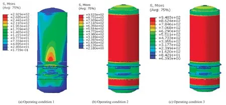
Figure 15 Mises stress of static load test motor case
4.3 Stress Simulation Analysis of Solid Booster Joining with Liquid Core Stage
Based on the simulation model of the case joining structure in the subscale test,a finite element simulation model for stress analysis of a solid booster motor joining with liquid core stage was established (see Figure 17).The MPC/joint ball hinge joining mode was established to simulate the angle compensation function of the ball hinge structure of main thrust transmission point.The position of auxiliary thrust transmission adopts the MPC hinge mode to simulate the angle and axial displacement compensation function of the ball hinge structure for the auxiliary thrust transmission point.

Figure 17 Finite element model of stress simulation for solid booster joining with liquid core stage
The calculation and analysis were completed under four load conditions (see Table 4).The stress of propellant is shown in Figure 18.It can be seen that the structural integrity of grain meets the requirements for use under the combined action of concentrated load at the joint and internal pressure load,and the concentrated load at the joint has no obvious influence on the stress and strain of grain.

Figure 18 Mises stress of solid propellant in stress simulation of solid motor joining with liquid core stage

Table 4 Load conditions of stress analysis of solid booster joining with liquid core stage
5 THRUST IMBALANCE CONTROL TECHNOLOGY FOR SOLID MOTOR PAIRS
There is always thrust imbalance between solid boosters due to various reasons,which will produce an overturning torque on the main body of the launchers with strap-on solid boosters,thus affecting the flight stability of the rocket and increasing the complexity of the control system and difficulty of rocket design.In order to ensure the reliability of launchers with strap-on solid boosters,foreign countries have tried to solve the problem through the performance of the solid motor,structure installation,and rocket control system etc.,to minimize the adverse impact of thrust imbalance.
5.1 Thrust Imbalance Factor Analysis of Solid Motor Pairs
Foster et al.,professors in the aerospace engineering department of Auburn University,analyzed thrust imbalance of solid boosters,and believed that the action time variability was one of the most important factors leading to thrust imbalance.The influence of action time difference on thrust imbalance is mainly manifested in the ascent phase (ignition transient) and descent phase of internal ballistic thrust.The corresponding thrust gradient in these two phases is very large,and a small time deviation will lead to a large thrust imbalance.
The main reasons affecting the deviation of action time are as follows: the deviation of propellant mass flow rate between ignition device and combustion chamber,the deviation of opening pressure of nozzle closure,the deviation of ablation rate of throat insert and the deviation of temperature field in the propellant grain.
The main factors affecting the mass flow rate of propellant in the ignition device and combustion chamber include burn rate and density of propellant,geometrical size and burning area of propellant grain.The burn rate coefficient,burn rate temperature sensitivity coefficient,pressure index and density of propellant are all determined by the propellant formulation.However,in the actual production process,the propellant formulation,raw material properties and their weighing and mixing,slurry casting and curing processes are not completely consistent,resulting in slight deviations in the density and combustion performance parameters of different batches and different bowls of propellant.The geometrical dimension and burning area of the grain are affected by the geometrical dimension deviation of the combustion chamber shell and insulation layer in the actual production process.
The large nozzle closure is generally fixed on the nozzle throat insert entrance in the form of bonding and opened in the form of blasting (shear failure).Therefore,the main factors affecting the opening pressure of the closure include tensile strength of the material and structural size of the closure.The range of tensile strength index of aluminum alloy used in nozzle closure is wide (about 60 -100 MPa),resulting in a wide range of pressure dispersion when the closure is opened.The opening pressure is affected by the thickness of the nozzle closure and other structural tolerances.
C/C composite material is generally used for large nozzle throat insert to reduce the ablation rate,so as to reduce the ablation rate deviation.However,the performance stability of C/C throat insert material is insufficient,and the mean value and dispersion coefficient between production batches are in great difference,resulting in large deviation of ablation rate of the throat insert.The main factors affecting the ablative performance of the throat insert include carbon fiber properties,preformstructure,material density,porosity,graphitization degree and impurities,plus some of the factors interact with each other.
Inconsistent temperature field of propellant will lead to inconsistent burning rate,resulting inaction time variation to a certain extent.
5.2 Design Method for Reducing Thrust Imbalance Between Solid Motor Pairs
Based on the analysis on thrust imbalance factors between solid motor pairs,some corresponding improvement measures were put forward from design and technology to reduce thrust imbalance.The design methods of reducing thrust imbalance mainly include internal ballistic design and nozzle closure design.
5.2.1 Thrust imbalance reduced by internal ballistic design
The most serious situation of thrust imbalance between the motor pairs is at the internal ballistic descent section.The thrust during the later operation period can be reduced or the descent section time can be prolonged in the internal ballistic design of motors to reduce the thrust variation gradient and the degree of thrust imbalance.The maximum thrust of the Space Shuttle and Ariane 5 solid boosters in the thrust descent phase was only about 50% of the initial maximum value,and the thrust descent period was very long (20 s and 30 s respectively),which effectively reduces the difficulty of thrust imbalance control and ensures flight stability.
For solid boosters,through design of grain configuration,the descent phase time can be prolonged and the thrust gradient can be reduced to a certain extent.
For segmented solid boosters,propellant in different segmented chambers can be designed with different burn rates to achieve a better effect.Take a certain segmented solid motor as an example,with 2.1 s action time difference,shown in Figure 19,and the maximum thrust imbalance is 440 kN.If the burn rate of the front and rear section of grain is adjusted from the design value r mm/s to (r+0.3) mm/s and (r-0.1) mm/s respectively,the maximum pressure of the motor increases by about 0.2 MPa when the action time difference remains unchanged,but the descent section of the internal ballistics increases from 9 s to 15 s,and the maximum thrust imbalance decreases to 266 kN.It can be seen that the differentiated design of propellant burn rate can effectively extend the descent stage time,significantly reduce the maximum thrust imbalance,and reduce the development difficulty of boosters.
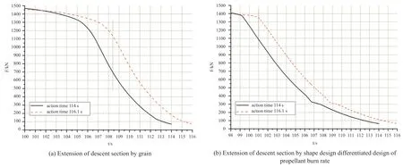
Figure 19 F-t curve of 2.1 s action time difference of the segmented solid motor
5.2.2 Reduction of opening pressure deviation of nozzle closure
The main factors affecting the opening pressure of the closure are the tensile strength and structural size of the closure material.The same sheet is used to process and form the closure of two nozzles of motor pairs to ensure the same material performance index.At the same time,reducing the tolerance range of key structural dimensions that affect the opening pressure of closure and strictly controlling the machining accuracy during the machining process can reduce the opening pressure deviation of the closure.
Under the premise of not affecting the reliability of motor ignition and the acceleration of internal ballistic ascent section,appropriately reducing the design value of opening pressure of the closure is also favorable to reducing the opening pressure deviation of closure.
5.3 Technological Measures for Reducing Thrust Imbalance Between Solid Motor Pairs
According to the factors affecting thrust imbalance of solid motor pairs,the corresponding technological control measures are mainly proposed from the aspects of motor development,storage and transportation,as shown in Table 5.
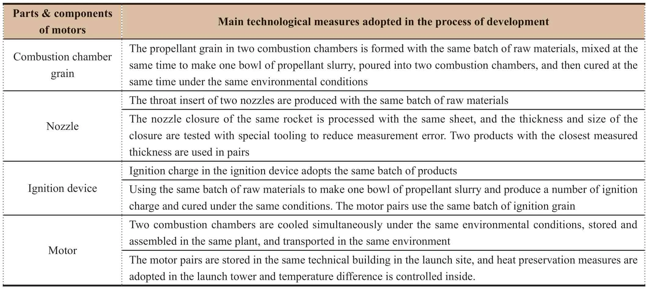
Table 5 Technological measures of thrust imbalance control in motor development
5.4 Test Verification of Thrust Imbalance Control Technology
In the flight test of a launch vehicle,the ratio of measuredthrust imbalance to average thrust during action time (relative thrust imbalance) of four solid boosters is shown in Figure 20.It can be seen that the maximum relative thrust imbalance of motor pairs during action time are 3.25% and 4.69% respectively,which can meet the requirements for rocket flight control.
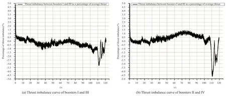
Figure 20 Relative thrust imbalance of four solid boosters
6 CONCLUSION
The key technologies of segmented solid boosters have been tested and verified systematically through single item test,static test and flight test successively,and the motor performance can meet the requirements for rocket flight.
However,the space launchers with strap-on solid boosters have just started in China,and it is still necessary to continue research on key technologies,optimize motor design and production processes,further improve product quality and working reliability,thus laying a solid foundation for subsequent extended application of large segmented solid motors.
杂志排行
Aerospace China的其它文章
- Research on Unattended Loading Technologies of the New Generation Launch Vehicles
- Adaptive Reconfiguration for Launch Vehicle Under Servo Mechanism Fault
- Application and Research of High-Power Electric Servo System on Launch Vehicle
- Research and Application of High-Voltage Power Supply and Distribution on Launch Vehicle
- Research on Modal Test Technology of LM-6A Solid-Liquid Strap-On Launch Vehicle
- Study on the Effect of Solid Particles on Jet Flow and Base Thermal Environment for Solid-Liquid Bundled Rocket
