Research and Application of High-Voltage Power Supply and Distribution on Launch Vehicle
2022-10-29WANGMengGAOLiYANGXinruXINGaoboYANFengWANGShudan
WANG Meng ,GAO Li ,YANG Xinru ,XIN Gaobo ,YAN Feng ,WANG Shudan
1 Shanghai Institute of Astronautic System Engineering,Shanghai 201109
2 Shanghai Institute of Space Power-Sources,Shanghai 200245
Abstract: High-power electric actuators are generally used on solid propellant motors,which further enhances the requirement on onboard supply voltage and output power of a launch vehicle.In this paper,combined with the electrical demand of China’s new generation solid-liquid bundled launch vehicle (LM-6A),high-voltage battery technology,high-power switch control technology,insulation protection technology under low pressure are studied,and the key technologies and schemes are presented.The flight test of LM-6A shows that the high-voltage power supply and distribution technology adopted is reasonable and feasible,and can be used as a reference for the designs of other launch vehicles or spacecrafts.
Key words: launch vehicle,high-voltage power supply and distribution,lithium-ion battery,insulation protection
1 INTRODUCTION
With the continuous improvement of launch vehicle configurations,solid propellant motors are being more and more widely adopted in launch vehicles.The swing control of a solid propellant motor generally adopts a high-power electric actuator,which further enhances the requirements on the onboard supply voltage and output power of a launch vehicle.Taking China’s new generation solid-liquid bundled launch vehicle(LM-6A) as an example,the rated power supply voltage of the electric actuator is 270 V,and the current is about 25 A during steady-state operation,with a pulse current up to about 150 A during large angle operation.The traditional power supply bus of a launch vehicle generally adopts 28 V,and the power supply current is about dozens of amperes.The voltage and power demand of the electric actuator is much higher than the traditional power supply capability of a standard launch vehicle.
The application of a high-voltage power supply and distribution technology on a launch vehicle should focus on high-voltage battery technology,high-power switch control technology,low-pressure insulation protection technology and so on.During the flight of a launch vehicle,atmospheric pressure goes from normal pressure to low pressure,and then into a near vacuum state.However high voltage may discharge in low pressure environment,and affect the flight mission.The strong vibration and high temperature produced by launch vehicle engines also increase higher requirements for system and device design.
2 DOMESTIC AND FOREIGN DEVELOPMENT
The adoption of a high-voltage power supply and distribution system in foreign launch vehicles was earlier than for domestic launch vehicles.The thrust vector control system of the Japanese H-IIA solid booster (SRB-A)adopted an electric actuator with 270 V and 105 A.The block diagram is shown in Figure 1.The power supply and distribution of H-IIA actuator was composed of a thermal battery and distribution device(APDU).APDU contains power resistors and power transistors,which can negate the reverse current generated during the operation of the electric actuator to suppress the influence of the reverse charging current on the thermal battery.
The sub-stage servo system of ESA's VEGA launch vehicleincludes a set of lithium-ion batteries,an IPDU and two electromechanical actuators,as shown in Figure 2.The lithium-ion battery was composed of six 60 V/200 A battery modules in series.The battery module consists of 15 VL8P lithium cells,that are from SAFT of France,are in series.The IPDU device consists of a main power switch that controls the battery’s output to the inverter.There are two identical inverters.In order to prevent corona generation,the IPDU adopts a sealed structure.
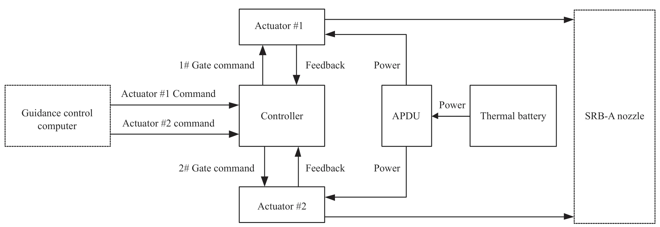
Figure 1 The composition of H-IIA launch vehicle servo system

Figure 2 Composition of VEGA electric actuator system
With the development of launch vehicles in China,the high-voltage power supply and distribution technology has been studied for launch vehicles.High-voltage power supply systems (270 V) are described as one of the development directions for launch vehicle electric systems in the references.An energy system with a high-and low-voltage hybrid bus architecture for a launch vehicle has been studied in reference.LM-6A,which is China’s first solid-liquid bundled launch vehicle,takes the lead in using the 270 V high-voltage power supply and distribution technology for the power supply of the 20 KW electric actuator.On March 29,2022,the first flight of LM-6A was a completed success,signifying a breakthrough in China’s high-voltage and high-power supply and distribution technology.
3 KEY TECHNOLOGIES
3.1 System Architecture
LM-6A is a new generation of solid-liquid bundled launch vehicle with four 2 m two-stage solid boosters.One single solid booster is equipped with two electric actuators for swing control.The flight time of the solid boosters is about 120 s.According to the power demand of the two electric actuators,a set of 270 V high-voltage battery and a high-voltage distributor are used to control the power supply and distribution on a single booster.The system architecture is shown in Figure 3.

Figure 3 Block diagram of high-voltage power supply and distribution system
3.2 Design of High-Voltage Battery
3.2.1 Selection of high-voltage battery
Both the lithium-ion battery and thermal battery have been applied as power supply of electric actuators on launch vehicles.
The thermal battery is a kind of thermal activated battery that uses its own heating system to melt non-conductive solid salt electrolyte into an ionic conductor to transfer into a working state.When it is in use,the electric ignition head inside the battery is ignited by an external current,so as to ignite the heating material inside the battery.This causes the internal temperature of the battery to rise rapidly,causing the salt electrolyte to melt and conduct electricity,thus activating the battery which outputs electric energy.The thermal battery has the characteristics of long storage time,short activation time,high output current density,high specific power,wide operating temperature range,and no maintenance is required during storage.Due to the special power output mode of the thermal battery,power output can only be generated after activation.Once the battery is activated,it becomes irreversible and disposable,so cannot participate in the system test and has certain limitations in test coverage.
The lithium-ion battery refers to the secondary battery with Li+intercalated compounds as positive and negative electrodes as the active substances.Lithium metal compounds are generally used as positive electrode active substances,while carbon materials are generally used as negative electrode active substances.The lithium-ion battery has a high specific energy,low self-discharge rate,and can be repeatedly charged and discharged (up to 800 charge-discharge cycles in 100%DOD),thus it is relatively convenient to use.So,the lithium-ion battery can participate in the system test and has good testability.The lithium-ion battery has been widely used in launch vehicles.
The performance comparison of the two kinds of battery is shown in Table 1.Considering testability and simplicity,LM-6A adopts lithium-ion battery as the power supply for the electric actuator.

Table 1 Comparison of battery performance
3.2.2 High-voltage Battery Pack Solution
According to the requirements of the electric actuator,the rated output capacity of the battery should be 10 Ah.The battery steady discharge current being 5-25 A,the maximum pulse current is 150 A,the maximum pulse discharge voltage is not less than 240 V,and the instantaneous pulse power is not less than 36 kW.The power performance of lithium-ion battery is mainly affected by the cathode material.The performance of the common cathode materials is shown in Table 2.

Table 2 Performance comparison of cathode materials for lithium-ion batteries
According to the performance comparison results of the cathode materials,LiNiCoMnOwith a better power performancewas selected as the cathode material of lithium-ion battery.Functional electrolyte was used as the electrolyte of monomer battery,which is composed of solvent,electrolyte and additive in appropriate proportions.Functional electrolyte has preferable rate characteristics and is suitable for the high rate discharge demand of launch vehicle.In order to improve the thermal stability of the diaphragm,inorganic ceramics (such as AlO,SiO,ZrO,etc.) were used to modify the polymer diaphragm without affecting the electrochemical performance of the battery,.
The lithium-ion battery pack consists of cells fastened in series through strips and nuts.The power circuits were made of pure copper.During the discharge process of battery pack,especially with large current pulses,the tiny resistance in the power circuit could lead to an unsatisfactory pulse working voltage.Therefore,it was necessary to calculate the resistance and voltage drop of the internal connection loop of the lithium-ion battery pack.The results show that the total voltage drop of the lithium-ion battery pack during pulse discharge is about 0.43 V,which meets the output voltage requirements of high current pulse discharge.
The high-voltage Lithium-ion battery cell adopted a square aluminum sealing technology.To improve the insulation performance,the aluminum alloy shell for the battery cell was coated with polyimide film with high insulation performance.Each battery cell was isolated by an epoxy glass laminated sheet (0.5 mm thick) characterized by high-voltage resistance,to avoid generating capacitance between battery cells.It is as shown in Figure 4(a).
The high-voltage battery consists of three battery modules in series.Each battery module consists of 25 10 Ah cells in series.The high-voltage battery consists of 75 cells in series.Figure 4(b) shows a battery module.
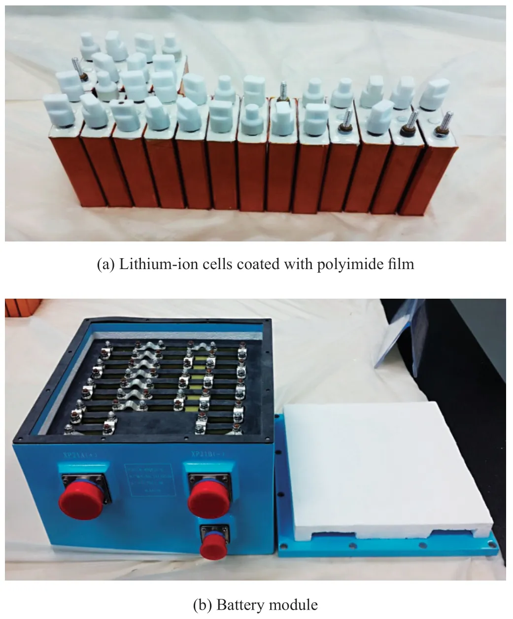
Figure 4 Lithium-ion battery
3.3 High-Voltage High-Power Switch Control Technology
The main driving circuit of permanent magnet synchronous servo motor includes the power supply,a soft start circuit,an inverter module,a filter circuit and an energy consumption circuit.The high-voltage Lithium-ion battery pack provided driving power for the servo motor.During the motor braking process,the stored energy of the motor inductor and the kinetic energy of the rotor need to be fed back to the DC bus in form of electric energy,which results in a rapid increase of the bus voltage.If the bus voltage increases excessively high,it will cause damage to the switching devices and capacitors in the power circuit.The lithium-ion battery pack can absorb the electric energy generated by motor braking and ensure the safety of the driving circuit.In order to provide the necessary reactive power to the motor and achieve a better filtering effect,the capacitors C1 and C2 on the main circuit have generally larger capacitance.When the main circuit is powered on,it will produce a large surge current to the system.A soft start circuit should be considered to protect the system.
The main circuit control switches K1 and K2 as well as the soft start switch K3 all adopt high-voltage contactors,the working principle is shown in Figure 5.Before K1 and K2 are connected,K3 is connected first,and the high-voltage battery pack charges the capacitors C1 and C2 through the current limiting resistor R1.After charging,K1 and K2 are connected.Rated working voltage of K1 and K2 was 270 V/150 A and K3 was 270 V/50 A.This contactor has excellent anti-vibration and anti-impact performance,and can adapt to the severe vibration environment during launch vehicle flight.
3.4 High-Voltage Insulation Protection Design
Paschen law describes the law of gas discharge under specific test conditions,as shown in Figure 6.The main factors causing discharge are as follows: electric field intensity,electric field uniformity,gas pressure,gap distance and gap filler.Discharge is proportional to applied voltage,the greater the applied voltage is,the greater the possibility of discharge is.Discharge is also related to the uniformity of the electric field,such as with sharp objects with small radius of curvature,so field strength is obviously stronger than other places,and it is easy to discharge.Another factor is the gas pressure.With the gas pressure decreasing,it is easier to discharge within a certain pressure range.Discharge is inversely proportional to the distance between the gaps,and the closer the distance is,the easier it is to discharge.The medium filled between the gaps also affect discharge.When at the same voltage,medium with relatively small dielectric constant is prone to spark and discharge.If the 270 V power supply voltage exceeds the lower limit of Paschen discharge curve at a certain distance and atmospheric pressure,so discharge may occur.According to the calculation,when the atmospheric pressure is between 1000 Pa and 100 Pa,partial discharge is the most common phenomenon during the flight of the launch vehicle.It is necessary to study the insulation protection design method under 270 V high-voltage power supply system according to the environmental characteristics of the launch vehicle.
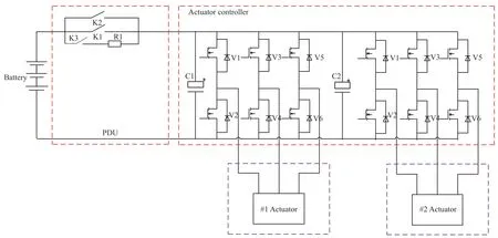
Figure 5 Main power supply circuit of electric servo system
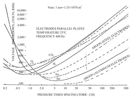
Figure 6 Paschen discharge curve
In order to avoid corona under low pressure,the high-voltage lithium-ion battery is designed with three battery modules in series,and the voltage of a single module does not exceed 105 V,which improves the safety under low pressure.The high-voltage switch control circuit is placed in a sealed high-voltage distributor,which is composed of a roof and a body.The junction surface between the roof and the body is filled with a conductive rubber seal strip coated with aluminum silver silicon oxide.The junction surface of the connector and the body is filled with a rubber ring made of a conductive rubber plate coated with aluminum silver.Holes for fastening relays,connectors,binding racks and printed boards are all designed as blind holes.For electrical connectors used for high-voltage transmission lines,O type sealing ring should be added at the junction between plug and socket to ensure that the internal air seal after docking.At the same time,in order to ensure the insulation performance of the solder joint at the tail of the electrical connector,a double-layer sealant sealing craft was adopted after the wire solder.The cable used for the high-voltage transmission line adopted a PTFE film and FEP combined insulation mode,so the insulation performance was above 1000 V dc under low pressure.
In order to avoid internal discharge of the high-voltage line,corresponding measures should be taken in craft.Solder joints near high voltage sections shall have no visible sharp edges,solder bumps,tin tips,inclusions (foreign matter) or strands of wire,and the solder joints shall be completely round with a continuous and smooth contour.All raised solder joints on the high-voltage line and the printed board near the high-voltage line are covered with silica gel to avoid the existence of raised electrodes.Before assembling the binding frame,the part of the binding frame in contact with the wire should be half-folded with polyimide insulating tape to strengthen the insulation.All metals within 20 mm from the high-voltage line shall be covered with polyimide insulating tape and further covered with silica gel.
4 TYPICAL TEST
4.1 Battery Discharge Test
In order to evaluate the performance of the high-voltage battery pack,discharging tests at normal temperature,high temperature and low temperature need to be carried out.When powering off the battery in a low-temperature environment,the battery should be heated to room temperature and then discharge according to the system environment.Figure 7 shows the discharge curves of battery at normal temperature (25°C)and high temperature (60°C,4 h).It can be seen that the battery can meet the requirement of 270 -340 V with constant discharge voltage of 5 A and 25 A.At 150 A pulse discharge,the voltage is higher than 249.7 V,which meets the minimum working voltage requirements of the electric actuator.
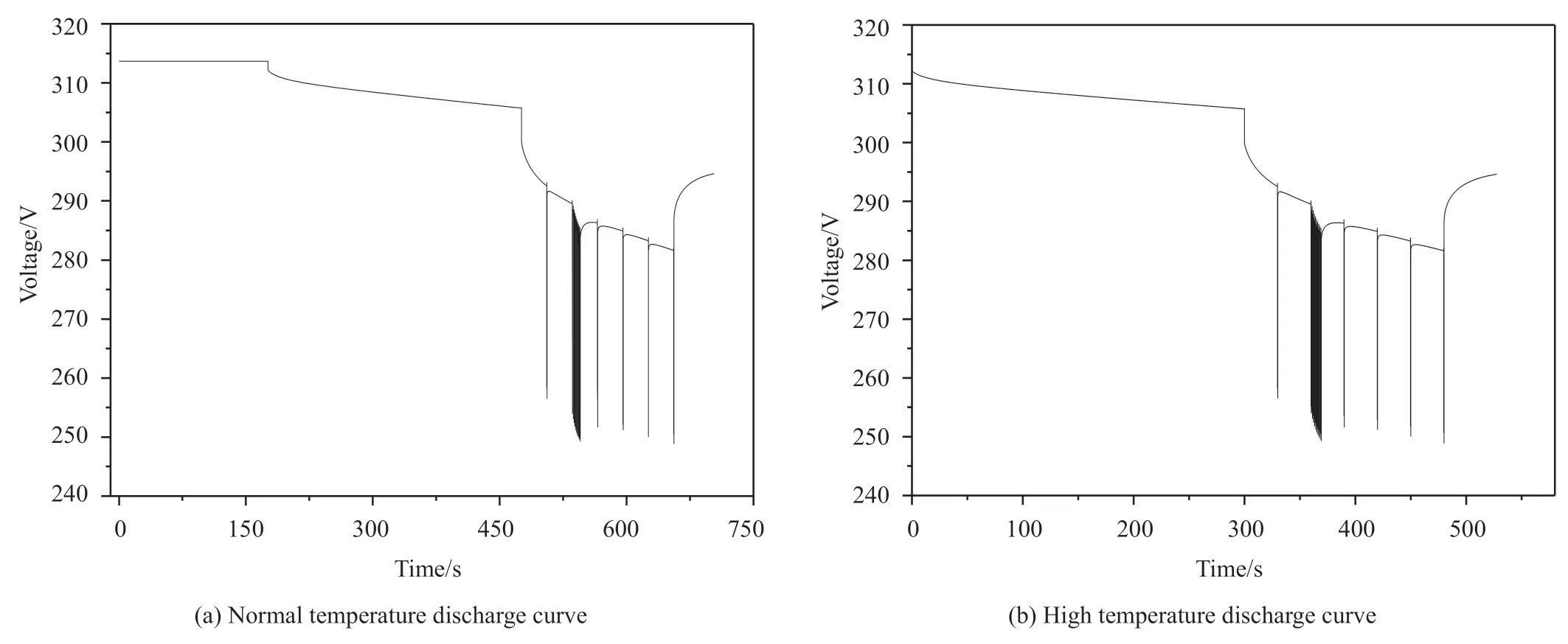
Figure 7 Battery discharge curve
In order to evaluate the adaptability of high-voltage battery pack to the reverse current generated during braking of the electric co-service system,a cell instantaneous reverse charge verification test was carried out.The maximum backfilling current generated by the electric co-service system was 150 A,and the longest duration was about 200 ms.Under normal temperature and pressure,two cells (#1 Cell and #2 Cell)were charged at 2 A constant current to 4.2 V,then charged at 4.2 V constant voltage to a 0.2 A cut-off current,stood for 30 mins,and finally charged at 150 A reverse current for 200 ms.At the end of the test,testers recorded the voltage of a single battery at 150 A reverse charge.The test results are shown in Table 3 and Figure 8.The monomer voltage increases slightly under the action of reverse current,but does not exceed the maximum voltage requirement,indicating that lithium-ion battery can adapt to the requirements of reverse charge of electric co-service system.

Table 3 Reverse charging test data of battery cell

Figure 8 Reverse charging test curve of battery cell
The high-voltage battery pack and the electric servo system have been carried out many physical docking tests.According to the requirements of flight swing curve,the electric co-service system is rocked on the engine load table.The tests show that the high-voltage battery pack output capacity and the absorption capacity can meet the requirements of two electric actuators on one booster.
4.2 Low-Pressure Test
In order to further evaluate the performance of the highvoltage device in a low-pressure environment,a low-pressure test is carried out.The test scheme is shown in Figure 9.During the test,the equipment state is consistent with the flight state.The test process simulates the flight environment of the launch vehicle,and the air pressure gradually decreases from atmospheric pressure to 10000 Pa,2000 Pa,1600 Pa,1000 Pa,700 Pa,400 Pa,200 Pa,100 Pa,50 Pa,10 Pa,0.03 Pa.The test voltage gradually increases from 200 Vdc to 1000 Vdc.Checking the leakage current between the positive and negative line,between the positive or negative line and the shell,and between the positive or negative line and the low-voltage line were conducted.
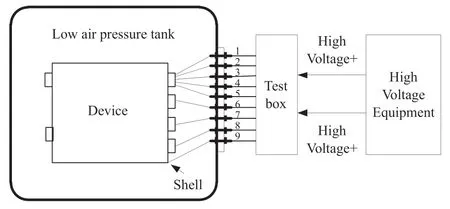
Figure 9 Low-pressure withstand test scheme
The test results are shown in Table 4.The test results show that the leakage current is about 0.02 mA,and no corona occurs.The insulation protection design met the requirements of launch vehicle.
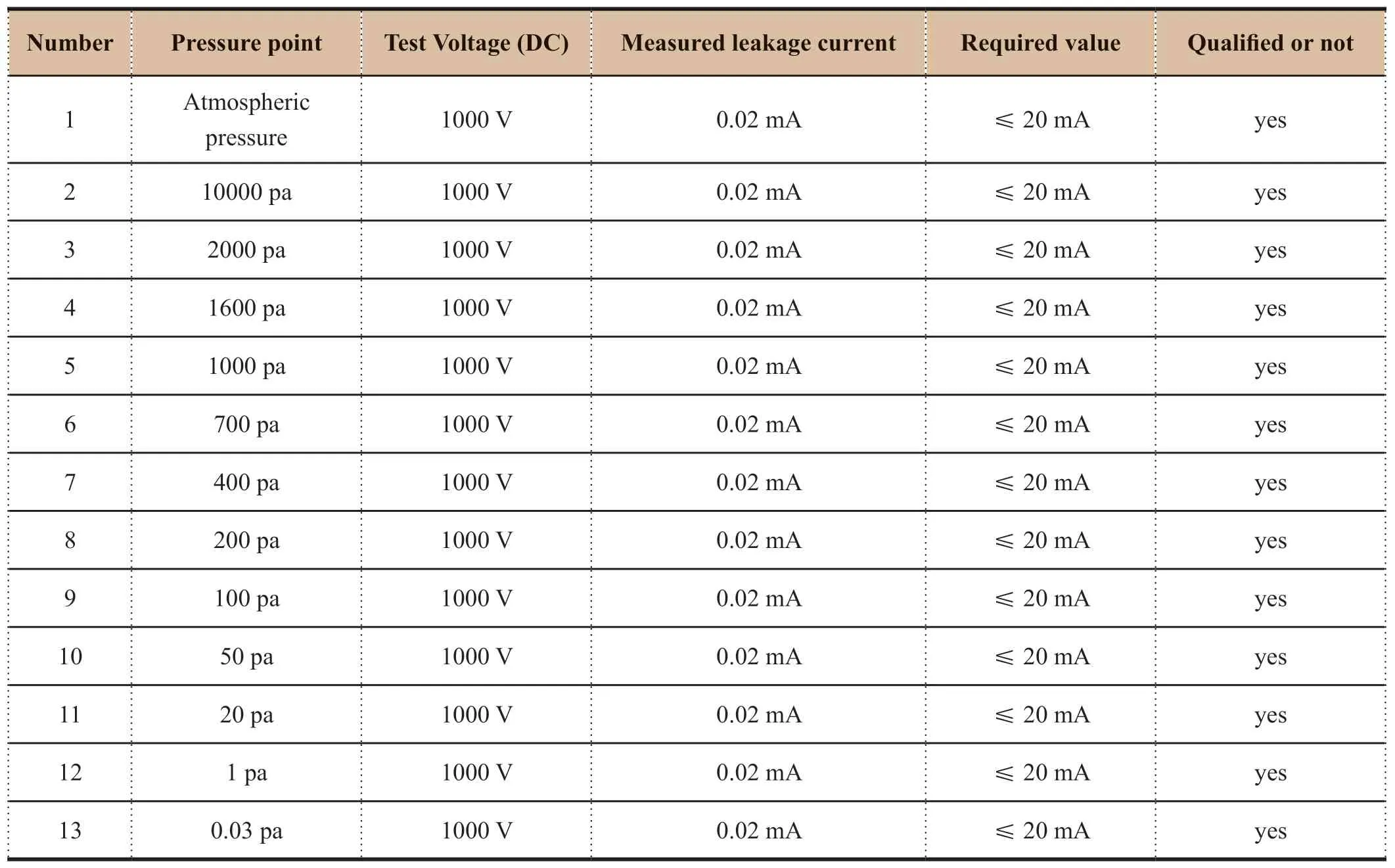
Table 4 Low-pressure test
4.3 Mechanical and Thermal Tests
The high-voltage power supply and distribution system was installed near the nozzle of the solid motor.During the launch vehicle flight,the high-voltage devices have to experience strong vibration and thermal environment.Those devices must pass strict mechanical and thermal environmental examination on the ground.In the mechanical and thermal environment assessment,it was necessary to pay attention to the output voltage variation of the high-voltage battery pack and the contact jitter of the high-voltage contactor to ensure the system works properly.According to the requirements of the launch vehicle environmental test,the high-voltage device ssuccessfully passed the temperature cycling test,cryogenic working test,instantaneous high temperature test,low frequency sinusoidal vibration test,high frequency random vibration test,impact test,overload test,humid heat test and so on.
The high-voltage power supply and distribution system successfully made its first flight on the LM-6A launch vehicle,which fully verified the environmental adaptability and operational compatibility on the launch vehicle.
5 CONCLUSION
Application of the high-voltage power supply and distribution system on a launch vehicle is studied in this paper,included the high-voltage battery technology,high-voltage switch control technology,high-voltage insulation protection technology,solving the high power supply requirements for the electric actuators,so enhancing the level of the power supply systems on the launch vehicle.
杂志排行
Aerospace China的其它文章
- Research on Unattended Loading Technologies of the New Generation Launch Vehicles
- Adaptive Reconfiguration for Launch Vehicle Under Servo Mechanism Fault
- Application and Research of High-Power Electric Servo System on Launch Vehicle
- Research on Key Technologies of Segmented Solid Rocket Booster
- Research on Modal Test Technology of LM-6A Solid-Liquid Strap-On Launch Vehicle
- Study on the Effect of Solid Particles on Jet Flow and Base Thermal Environment for Solid-Liquid Bundled Rocket
