Research on Modal Test Technology of LM-6A Solid-Liquid Strap-On Launch Vehicle
2022-10-29ZHUChunyanYANGBingDIWenbinCHANGDongfangMAOYuming
ZHU Chunyan,YANG Bing,DI Wenbin,CHANG Dongfang,MAO Yuming
Aerospace System Engineering Shanghai,Shanghai 201109
Abstract: The LM-6A new generation solid-liquid strap-on launch vehicle has the structural dynamic characteristics of lower frequencies,denser modes and coupling modes in longitudinal,bending and torsion modal space.During the development phase of LM-6A,modal tests of partial stacks and the full vehicle were designed to obtain the structural dynamic properties.The structural dynamic models using the finite element method (FEM) have been verified and calibrated based on the modal test data.This paper describes the pre-test predictions and test execution,and details the comparison between the pre-test predictions and the test data.The successful maiden flight of LM-6A further confirmed the effectiveness of structural dynamic modeling and modal test for LM-6A.
Keywords: LM-6A,modal test of full vehicle,partial stack modal test
1 INTRODUCTION
During the development phase of the LM-6A launch vehicle,a series of modal tests were designed to verify the dynamic finite element model used in the loads assessment,flight control evaluationsand POGO stability design.Compared with the simulation analysis,it is generally believed that a ground modal test can obtain more realistic data of the dynamic characteristics of the launch vehicle,and determine gyro bracket locations more accurately.With the improvement of computer performance,the simulation accuracy has gradually improved,but the ground modal test is still an important means to obtain the dynamic parameters of the launch vehicle.
In order to obtain the accurate dynamic parameters of a launch vehicle,a large number of ground modal tests have to be conducted.During the development of Saturn V,NASA carried out 1/40,1/10 and full-scale modal tests until the simulation results were consistent with the test data.Higher requirements are put forward for the consistency of simulations and tests for the manned spaceflights.Based on the 1/8,1/4 and full-scale modal tests,whole rocket modal tests were carried out for the manned spaceflights by NASA.Although Ares I-X did not enter service in the end,sufficient multi-conditional modal tests were conducted in the upright state and the pre-launch state during the development period.The well-known launch vehicle of ESA,Ariane 5,despite not adopting a full vehicle modal test to obtain its modal parameters,was disassembled into three large parts and refined modeling was used to obtain modal characteristics data.
Up to now,with the exception of LM-8 where the dynamic parameters of the full vehicle using the combined module and the pre-launch state modal testswere obtained,the development of China’s other launch vehicles was still based on the ground modal tests.For example,the second full modal test was conducted in order to solve the POGO problem of LM-2FThe full modal tests of LM-7 and LM-5 were conducted in the newly built modal test tower in Tianjin in 2013 and 2015 respectively.At that time,the test technology for the strap-on launch vehicle was explored for the first time and the complex modal characteristics of a strap-on launch vehicle were studiedin China.
2 NECESSITY ANALYSIS OF MODAL TEST OF LM-6A
At 17:50 Beijing time on March 29,2022,a LM-6A launch vehicle was launched into space from the Taiyuan Satellite Launch Center.As China’s first medium-lift launch vehicle with solid motor boosters,its successful maiden flight marked the addition of a new member in China’s launch vehicle family,and further perfected the construction of China’s next generation of non-toxic and pollution-free launch vehicles.
Modal tests of LM-6A were also conducted at the Tianjin modal test tower.Compared with the LM-5 and LM-7 launch vehicles,the biggest difference with the LM-6A was that four solid motor boosters were equipped,which was the first time for China.Like the liquid strap-on launch vehicles,LM-6A has common dynamic characteristics such as lower frequencies,denser modes and more difficult to identify.It also has unique characteristics,which needed to be investigated and studied during the ground modal tests,including but not limited to:
1) It is inefficient and hard to fill the solid propellant grain on site.Unlike the liquid booster that can be set up under different working conditions by adjusting the liquid level height,the solid booster can only be set to empty or full working conditions.That is why there were only two modal test articles,empty and full grains respectively.
2) The flexible nozzles of solid boosters exhibit different dynamic properties under empty and full grain state.The local modes of the motor will change with the propellant consumption.
Therefore,in addition to obtain the natural frequencies,mode shapes,damping ratio and establishing gyro bracket locations in the full modal test,it was necessary to fully investigate the unique dynamic characteristics of the solid-liquid strapon launch vehicle.The ground test data can promote further refinement of the dynamic finite element model.Since only a high-precision simulation model can meet the requirements of attitude control,POGO stability and load design,it was necessary to carry out the LM-6A full modal tests.
To control cost and optimize the test,the modal characteristics of the solid-liquid strap-on launch vehicle were pre-tested using a simulation model before the actual modal test.Locations of accelerometers and shakers were established using the pretest finite element method (FEM).For most modal tests,the measurement engineers’ experiences in installing accelerometers and shakers are very important due to the limited number of accelerometers and shakers.In the modal test,the modal data was obtained by means of spatial multi-point excitation and a pure modal acquisition system.Next,the control gyro bracket locations were established under several specific conditions.Finally,these were used to validate and refine the finite element models by comparing simulation results with test data.
3 PRE-TEST ANALYSIS
3.1 Test Article
LM-6A test articles consisted of a two-stage core with the liquid oxygen/kerosene engines and 4 solid motor boosters.The propellant of the tanks was approximately replaced by pure water of the same mass while conducting the modal test.During the test,the solid boosters could not be directly filled at the test site like the liquid tank.In addition,it was not allowed to transport the boosters back to the assembly building for propellant powder filling considering the test efficiency.Thus,two sets of boosters were directly put into production: one set with empty grain state and one set with mass simulators of grain.Figure 1 shows the LM-6A test articles in the modal tower in Tianjin.
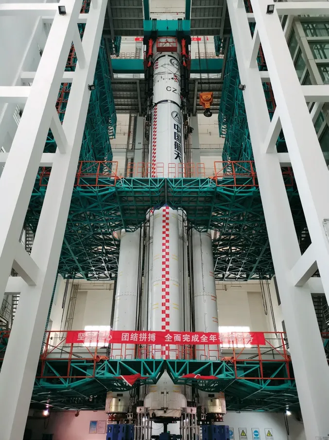
Figure 1 LM-6A modal articles in modal tower
3.2 Test Conditions and Process
In the early modal tests for full launch vehicles in China only the operating conditions corresponding to the flight state were conducted.In order to fully investigate the characteristics of sub-stages and provide more effective data for dynamic modeling and improvement,LM-6A had a series of sub-stage/partial stack tests conducted in addition to several full tests.Figure 2 shows the test cases and test flow diagram used for LM-6A,including 9 flight modal test cases and 6 partial stack modal test cases.The 9 flight modal test cases were:
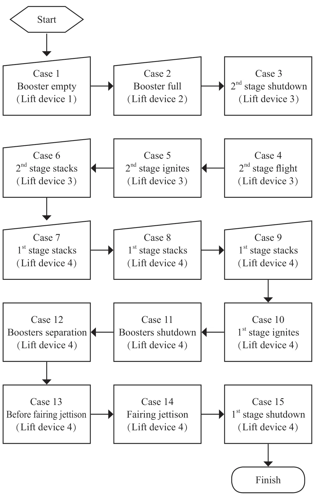
Figure 2 Test cases and test flow diagram
Case 3: shutdown state of the 2nd stage;
Case 4: medium flight state of the 2nd stage;
Case 5: ignition state of the 2nd stage;
Case 10: ignition state of the 1st stage;
Case 11: booster shutdown state of the 1st stage;
Case 12: booster separation state of the 1st stage;
Case 13: before fairing jettison of the 1st stage;
Case 14: after fairing jettison of the 1st stage;
Case 15: main engine shutdown of the 1st stage,respectively.
The 6 partial stack modal test conditions were:
Case 1: booster in empty grain state;
Case 2: booster in full grain state;
Case 6: partial stack modal test of the 2nd sub-stage,test articles were two empty tanks of the 2nd sub-stage,a liquid engine and inter-tank section;
Case 7: partial stack modal test of the 1st stage,test articles were two empty tanks of the 1st sub-stage,4 liquid engines and inter-tank section;
Case 8: partial stack modal test of the 1st stage,test articles were two empty tanks of the 1st sub-stage,4 liquid engine,inter-tank section and 4 boosters in empty grains;
Case 9: partial stack modal test of the 1st stage,test articles were two full tanks of the 1st sub-stage,4 liquid engine,inter-tank section and 4 boosters in full grains,respectively.
3.3 Pre-test Results
The solid-liquid strap-on launch vehicle has not only the modal characteristics of a liquid-liquid strap-on rocket,but also the dynamic characteristics of solid motors.Although the pre-test analysis could not accurately predict all of the modal properties,the frequency range and mode shapes could be preliminarily calculated based on the results of simulation analysis before the test.See Figure 3 for the partial frequencies from FEM of the 1st stage.In the figure,x-coordinate represents 1st stage test conditions,y-coordinate represents the frequencies,Case 10 to Case 15 respectively represent 1st stage ignition state,booster shutdown state,after booster separation state,before fairing jettison state,after fairing jettison state and 1st stage shutdown state.Similarly x-coordinate in the following figures have the same meaning.
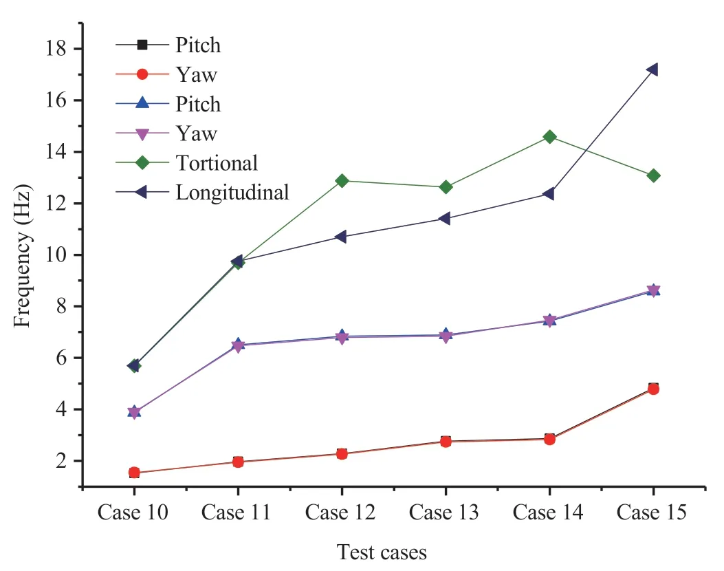
Figure 3 1st stage partial frequencies of pre-test from FEM
In addition to the 1st flight stage case,the simulation values of the first pair of bending frequencies of the single solid booster are given here,17.50 Hz,17.50 Hz while being full grain,and 40.93 Hz,41.14 Hz while being empty grain respectively.We need to pay special attention to the different characteristics exhibited by the solid booster flexible nozzle in the full grain state.
4 TEST DESCRIPTION AND EXECUTION
4.1 Test execution process
Figure 4 shows the implementation process of one of the 1st flight stage case.After the full frequency band has been swept roughly,a specific frequency band was carefully swept by a sinusoidal excitation force.At this time,it was necessary to judge whether the critical modes are missed according to the pre-test results.If there were any omissions,the locations of the shakers had to be adjusted or other methods adopted.After adjustment,the next step would be conducted.After the fine sweep in different frequency bands,the pure modal test of one mode was carried out to complete the acquisition of the modal parameters (natural frequencies,damping factors,mode shapes and slope values).For each frequency,the amplitude of the excitation force needed to be adjusted to test the linearity of the modal test vehicle.
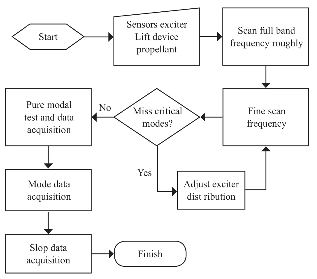
Figure 4 Execution of one of the flight stage case
4.2 Boundary Constraint
During the flight,the launch vehicle is in a free boundary condition with no constraint,however,due to the motor thrust action,the launch vehicle will be in a compression state.The flight boundary constraint cannot be completely reproduced during the ground test,so can only be approximated as much as possible.At present,the modal test in China basically adopts equipment lifting at the lower point with four-point suspension using elastic wire rope at the upper,and makes use of the weight of the test article itself to simulate compression state.Different from the booster support mode of the LM-5 rocket,the core-stage four-point support mode was adopted by both LM-6A and LM-7.Figure 5 shows the test lifting equipment of LM-6A in the modal tower.

Figure 5 Test lifting equipment of LM-6A in the modal tower
4.3 Locations of Accelerometers
The locations of the accelerometers need to meet several conditions,which can not only measure the vibration mode characteristics of the test vehicle,but also ensure that the MAC values of the off-diagonal elements of the main modes are small enough.For example,in reference [13],the sensitivity analysis is carried out through a modal kinetic energy algorithm to effectively remove the measuring points with small contribution.Finally,the off-diagonal element MAC value is guaranteed to be less than 0.2 (MAC=0 means that the two mode shapes are completely unrelated linearly).Of course,existing commercial software can also assist in the pre-analysis of accelerometers.For a slender structure such as launch vehicle,the above two points can be basically met according to existing experience.Figure 6 shows the locations of the 1st flight stage case accelerometers.

Figure 6 Accelerometers layout under the 1st flight stage case
4.4 Multi-channel Shaker Locations
There are many modes of excitation in the modal test.For example,impact excitation force can be applied by a hammer striking,ultra-low frequency excitation force can be applied by wind or hand shaking at the launch site,and sinusoidal excitation signals can be applied jointly by several shakers distributed along the article.Figure 7 shows the shaker locations used on LM-6A.Taking the 1st flight stage case as an example,the four figures respectively represent the pitch/yaw direction mode excitation,torsional mode excitation and longitudinal mode excitation.
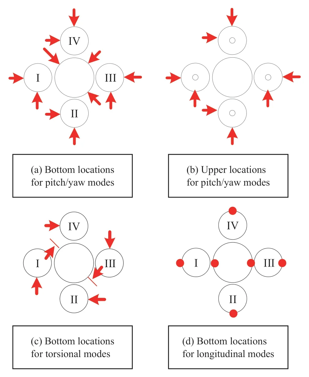
Figure 7 Spatial locations of the shakers
5 TEST RESULTS AND DATA ANALYSIS
5.1 Modal Results and Data Analysis
Due to many test cases,only two of the 1st flight stage cases are shown here.The x-coordinates in Figure 8-Figure 10 describe the vibration mode shapes.The six mode orders are the first two pairs of lateral bending vibration,the first order torsional vibration and the first order longitudinal vibration respectively.Figure 8 and Figure 9 show the natural frequencies of the 1st flight stage ignition and shutdown cases respectively,including two pairs of bending frequencies in pitch/yaw direction,one torsional frequency and one longitudinal frequency.As can be seen from Figure 8,in the 1st stage ignition case,except for the first pair bending vibration frequencies in the pitch/yaw direction,the FEM data was in good agreement with the test data.For the first pair of lateral bending frequencies,the FEM value is about 12% higher than the test value,which may be caused by the sloshing mass in the 1st stage ignition case.Figure 9 shows the result in the 1st stage shutdown state.It can be seen that the FEM values are in good agreement with the test values,including the first pair of bending vibration frequencies.
Figure 10 shows the first order lateral bending frequencies of the six test cases in the 1st stage flight case.As can be seen from the figure,with the consumption of propellant,the deviation between simulation value and test value turns from negative deviation to positive deviation.Therefore,further research should be carried out on simulation modeling of the propellant.
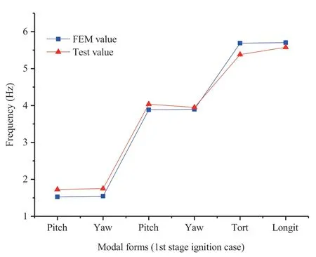
Figure 8 Frequencies comparison between simulated and test values

Figure 9 Frequencies comparison between simulated and test values
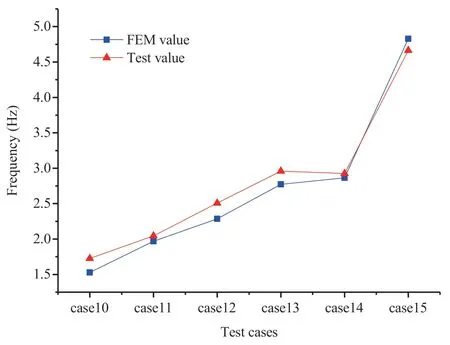
Figure 10 1st order frequency comparison between simulated and test values
Figure 11 shows the comparison between the FEM mode shapes and the test mode shapes of the 1st stage ignition case.In the figure,the red dotted line represents the test vibration mode shapes,and the blue grid line represents the FEM mode shapes.It can be seen that the mode shapes are consistent.In addition to the modes being obvious in the vibration of the core,the boosters also show obvious branching modes and the coupling modes between the core stage and the boosters.These modes are consistently reflected in the test and simulation,as shown in Figure 12.
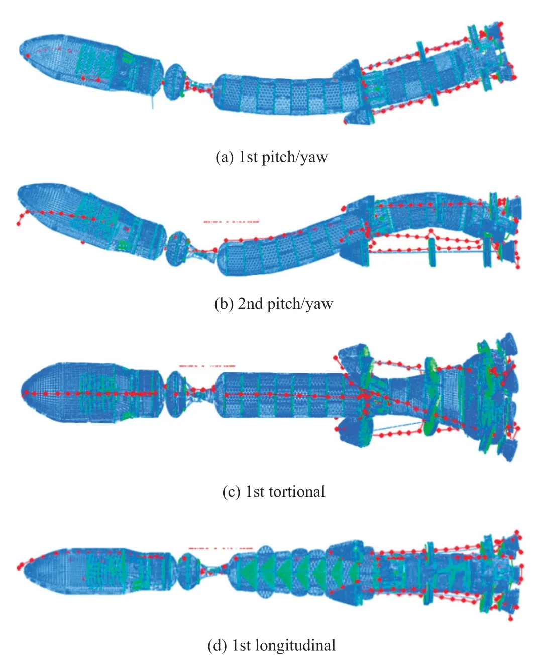
Figure 11 vibration mode shapes of 1st stage ignition case

Figure 12 Branch modes of boosters

Figure 13 Comparison of simulated and test slope values (1st stage ignition case)
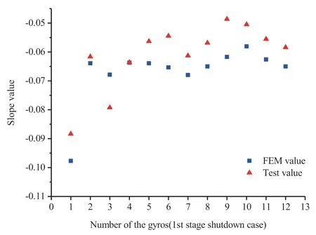
Figure 14 Comparison of simulated and test slope values (1st stage shutdown case)
5.2 Slope Results and Data Analysis
Figure 13 and Figure 14 show the comparison between the slope data from FEM and the measured data of first-order lateral bending vibration in the 1st stage ignition and shutdown cases respectively,and only the values of the main vibration directions are shown in Figure 13 and Figure 14.The values on the x-coordinate represent the gyroscope serial number and those on the y-coordinate represent the slope values.It can be seen from the figures that the absolute deviation of calculated values relative to test values is within ±0.01 except for some values whose absolute deviation exceeds ±0.01 (absolute deviation=test value -FEM value).In the design of the launch vehicle flight attitude stability,the slope deviation of the first-order lateral bending mode is ±0.02,so the calculated values are in good agreement with the experimental values.
5.3 Mode Results and Data Analysis of Boosters
Table 1 shows the comparison between the simulation frequencies and the test frequencies of the single booster.Figure 15 and Figure 16 are the mode shapes corresponding to the fullgrain state. In the table,the 2nd and 4th columns are the pretest values and the test values of the full grain state respectively.In addition,the first pair of bending vibration frequencies in the empty grain state are also given in the 5th and 6th columns.It can be seen that the test value in full grain state is 9.82 Hz,which indicates that the full grain state has an additional mode in low frequency compared to the empty grain state.It is generally considered that the nozzle local mode is basically stable when the liquid engine nozzle is in zero position.The special dynamic characteristics of the flexible nozzle of the solid booster in the fully grain state was not considered in the initial pre-test modeling.The 3rd column shows the values of the updated finite element model,the frequency of 9.70 Hz is close to the test value.If the booster motors are involved in attitude control,the local vibration of the flexible nozzle in full grain state must be taken into account.It can be seen that the single booster modal test is of great significance.
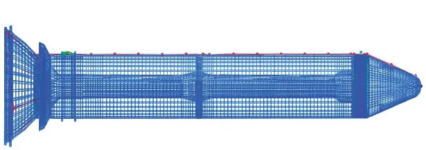
Figure 15 Local mode of flexible nozzle in full grain state

Figure 16 Firstpair bending vibration of solid boosters in full grain state

Table 1 Comparison between pre-test values and test values of a booster
6 CONCLUSIONS
The LM-6A modal tests were successfully completed in Tianjin modal tower.Through the tests,a large number of modal parameters for the solid-liquid strap-on launch vehicle were acquired,including 9 flight cases and 6 partial stack cases.The characteristics of lower frequencies,denser modes and modal coupling were further confirmed.In particular,the initial finite element model was found inaccurate not only for the first pair of natural frequencies at high tank levels,but also for the local mode of the flexible nozzle in the full grain state of the solid booster.Further research should be carried out on building the finite element model of the liquid propellant and flexible nozzle of the solid motor.Subsequently,the model was verified and modified according to the experimental data,which effectively supported the successful maiden flight of the LM-6A launch vehicle.
杂志排行
Aerospace China的其它文章
- Research on Unattended Loading Technologies of the New Generation Launch Vehicles
- Adaptive Reconfiguration for Launch Vehicle Under Servo Mechanism Fault
- Application and Research of High-Power Electric Servo System on Launch Vehicle
- Research and Application of High-Voltage Power Supply and Distribution on Launch Vehicle
- Research on Key Technologies of Segmented Solid Rocket Booster
- Study on the Effect of Solid Particles on Jet Flow and Base Thermal Environment for Solid-Liquid Bundled Rocket
