An effective rolling process of magnesium alloys for suppressing edge cracks: Width-limited rolling
2022-10-25JingTinHuihuLuWnggngZhngHuihuiNieQunxinShiJifeiDengWeiLingLifeiWng
Jing Tin ,Huihu Lu ,Wnggng Zhng ,Huihui Nie ,Qunxin Shi ,Jifei Deng ,Wei Ling,c,∗,Lifei Wng,∗
a College of Materials Science and Engineering,Taiyuan University of Technology,Taiyuan 030024,China
b Shanxi Key Laboratory of Advanced Magnesium-based Materials,Taiyuan University of Technology,Taiyuan 030024,China
c Instrumental Analysis Center of Taiyuan University of Technology,China
Abstract To suppress the edge crack of the magnesium alloy sheet during the ordinary rolling process,a new rolling process named width-limited rolling was proposed in this paper.Width-limited rolling is a rolling method in which the width of the alloy sheet is limited by modifying the shape of the rollers,allowing a compressive stress field to form at the edge portion of the alloy sheet during rolling,resulting in the reduction of edge cracks.At present work,magnesium alloy sheets were separately subjected to ordinary rolling and width-limited rolling.The microstructure evolution and mechanical properties of the rolled sheets were investigated by EBSD,TEM,and XRD.The results exhibited that under the same rolling conditions,the sheet after ordinary rolling exhibited obvious edge cracks while no crack was found at the edge of the sheet after width-limited rolling.The edge crack suppressing effect was attributed to the reduction of the tensile stress along rolling direction during WLR,promoting the synchronous extension of the edge and center regions to suppress edge crack tendency.Microstructure observation showed that the compressive twins formed in the sheet after ordinary rolling usually exhibited as thin plates and cannot continue to fully develop due to the premature generation of the edge cracks.However,the compressive twins developed maturely in some of which double twins formed and various slip systems with different dislocation Burgers vectors occurred in the rolled sheet after WLR.More twin intersections and shear bands,providing more potential recrystallization nucleation sites,which are beneficial to weaken basal texture.With the cooperation of twinning and dislocation slip,the texture of the sheet after the width-limited rolling is weakened and the mechanical properties are improved.
Keywords: Width-limited rolling;Texture;Twinning deformation;Dislocation;DRX.
1.Introductio n
Magnesium alloys are known as the highest potential green engineering material in the 21st century owing to their high specific strength,high specific stiffness,good thermal conductivity,damping properties,and electromagnetic shielding.As the lightest structural metal,magnesium alloy has broad application prospects and is widely used in fields such as aerospace,automotive,and electronics [1-4].Wrought magnesium alloys have better mechanical properties and dimensional stability than cast magnesium alloys.However,magnesium alloys have fewer independent slip systems and low room-temperature plasticity because of their close-packed hexagonal crystal structure,which facilitates cracking during plastic forming and impedes deformation,thus hindering their large-scale production.Therefore,improving the rolling process and rolling mode of magnesium alloy to solve the problem of edge cracking and thus improve the rolling forming performance and to obtain magnesium alloy sheet with excellent mechanical properties is urgently needed [5-8].
Extensive studies on how to improve formability and plasticity of magnesium alloys have been conducted.Grain orientation and grain size are closely related to the mechanical properties and the formability of magnesium alloys [9,10].Weaken texture can decline the strong anisotropy caused by the strong basal texture formed in rolled magnesium alloys,thereby improving the formability[11].Therefore,researchers are working to improve the ductility and strength of magnesium alloys by refining grains and controlling the basal texture.Besides,pre-twinning could be an effective method to improve the formability of magnesium alloys,not only coordinating plastic deformation but also leading the evolution of microstructure.
Researchers use different processing methods to change the microstructure of the magnesium alloys to achieve the purpose of improving the formability of the magnesium alloy and reducing-edge cracks Several methods such as equal channel angular processing (ECAP) [12],single-roller drive rolling (SRDR) [13],two-stage rolling [14],and differential speed rolling [15] can achieve grain refinement and weaken the basal texture to significantly improve the yield strength and ductility of the magnesium alloy at room temperature.Some new plastic processing techniques also have been developed to overcome this issue.Huang et al.[16] established that the prefabricated crown rolling process altered the stress distribution on the edge of magnesium alloy sheets,leading to the reduction of the tiny grains in the vicinity of the edge crack and uniform distribution of microstructure,and made the generation of edge cracks to be eliminated or delayed in rolled plates.Zhi et al.[17] reduced edge cracking through multi-pass cross-rolling,but it was also necessary to perform multi-pass rolling.Xin et al.[18] perform pre-rolling in the TD,and weaken the strong basal texture by twinning deformation and effectively increase the maximum thickness reduction per pass.But these methods have increased the number of processes and are not conducive to mass production.Therefore,how to effectively solve the edge cracking problem in the magnesium alloy rolling process and simplify the process at the same time to enable mass production are the problems to be addressed in this study.
A width-limited rolling (WLR) scheme was applied to the magnesium alloy sheet,in which the width of the magnesium alloy sheet is limited during rolling.The width limitation was realized by modifying the shape of the rollers,allowing a compressive stress field to form at the edge portion of the magnesium alloy sheet during rolling which changed the microstructure of the sheet,thus reducing the edge cracking tendency.
2.Experimental procedure
Fig.1a and b show the WLR and FR scheme.WLR means that the widening deformation in the transverse direction(TD)of the sheet is limited during the rolling process to subject the sheet to lateral pressure and suppress the generation of edge cracks to obtain a sheet with better mechanical properties.Hereafter,conventional rolling,in which the width of the sheet is free and not limited during rolling,is referred to as free rolling (FR).The force analysis of the magnesium alloy sheets during FR and WLR rolls are shown in Fig.1c and d,respectively.The sheet under FR is only subjected to the rolling force in the ND (normal direction),and the deformation along with TD and rolling direction (RD) is not limited.In addition to the rolling force in the ND like FR,the sheet under WLR also has a lateral pressure generated by the groove of roll in the TD.
The experimental material was a 3-mm-thick industrial hotrolled plate of AZ31 magnesium alloy.Small sheets were cut along the rolling direction of the hot rolled plate to a size of 70mm×60mm×3mm and then annealed at 300°C for 1h.The magnesium alloy sheets were preheated (at 400°C and held for 10min) and then rolled immediately.The magnesium alloy sheets were rolled to a thickness of 2.1mm by FR and WLR,respectively,corresponding to a rolling reduction of approximately 30%.And Abaqus finite element software was used to simulate these two kinds of rolling processes,in which the roll gap between the rollers was set to be 2.1mm.
The tensile specimens were cut from the sheets after FR and WLR along the TD.The mechanical properties of the sheets after FR and WLR were tested using a universal material testing machine (Instron 5969) with a crosshead speed of 0.5mm/min at room temperature.Tensile fracture surfaces were observed by a field emission scanning electron microscope (SEM;Tescan Mira 3).
Samples for microstructure observation were cut from the middle and edge of the sheets after FR and WLR.Microstructure characterization of the rolled magnesium alloy sheets was performed at the plane consisting of the TD and the normal direction (ND) and observed by using an optical microscope (OM;Leica-2500M).The macro texture of the middle and edge of the rolled sheets was characterized by X-ray Diffraction (XRD) using Cu Kαradiation on a Rigaku Smart Lab SE diffractometer at a scan rate of 5°/min and step size of 5°.The data of macrotexture from XRD were analyzed using the ResMat-TexTools.The observation of the samples from the edge of the rolled sheet was examined with a field emission scanning electron microscope(SEM;Tescan Mira 3)equipped with an electron backscatter diffraction(EBSD)system.EBSD specimens were grinding on 400,800,1200,1500,2000,and 3000 grit SiC paper and then electro-polishing at a voltage of 45V and an electric current of 0.05A for 45s at a temperature of -20°C.The step size of EBSD scan was set as 0.5μm and the received EBSD data were analyzed using Channel 5 software.TEM samples were prepared by electropolishing and observation was conducted with an accelerating voltage of 200kV.
3.Results
3.1.Edge cracks and simulated stress field

Fig.1.Schematic diagrams of roll: (a) FR;(b) WLR and Stress analysis of the sheet under different rolling methods: (c) FR;(d) WLR.

Fig.2.The images of the edge of magnesium alloy sheet after different rolling methods: (a) the sheet after free rolling;(b) the sheet after widthlimited rolling.
Fig.2a and b show macroscopic images of the edge portions of magnesium alloy sheets after FR and WLR,respectively.As can be seen,the magnesium alloy sheet exhibits serious edge cracking after FR,and the surface of the sheet is also rough.In contrast,no obvious edge crack is observed on the magnesium alloy sheet after WLR,and the surface is smooth.It can be confirmed that WLR effectively suppresses cracks compared to FR.
The rolling method is an important factor affecting the mechanical properties and rolling forming of magnesium alloy sheets.Different rolling methods of FR and WLR result in different sheet stress distribution,causing different edge cracking conditions of the sheet after rolling.To further explore the stress distribution of the sheets during FR and WLR,numerical simulation was carried out to investigate the effect of two rolling methods on edge cracks.
Abaqus simulations were performed to analyze the stress distribution of Mg alloy sheets during rolling.The geometry and size of the sheets and the rollers are the same as the experimental ones and the model is shown as Fig.3a and b.The material properties are list in Table 1.The simulatedsheet is rolled from 3mm to about 2.3mm by FR and WLR,respectively.The simulation results are shown in Fig.3.

Table 1 Material properties of AZ31B used for Abacus simulation.
The Numerical simulation results demonstrate that the stress distribution of the sheets under FR and WLR are different,and compared with FR,the groove of the WLR roller limits the deformation in TD of the sheet,and a compressive stress field forms at the edge of the sheet.
According to Mises stress distribution in Fig.3c and d,compared to FR,the stress distribution of the sheets at the rolling time under WLR changed.During WLR,the part of the sheet being rolled not only exist a stress field along ND generated by rolling force like FR but also exists a stress field due to the lateral pressure generated by the groove of roll along with TD.
As Fig.2 showed,the edge cracks propagate along with TD.Huang et al.[16] found that edge cracking also originated from the edge region suffering from large tensile stress during regular rolling of magnesium alloy,which made the asynchronous extension of the edge and center regions of the sheet.,leading to the appearance of edge cracks.So the normal stress in RD should play an important role in edge cracking.
From the normal stress distribution along the RD (Fig.3e and f),it can be seen that the sheet edges on both sides of the rolling position are subjected to large tensile stress during FR,which is about 143 MPa,as shown in the orange and red areas in Fig.3e.The tensile stress under WLR is about 100 MPa,as shown in the yellow and green areas in Fig.3f.It can be inferred the sheet under FR is subjected to large tensile stress in the RD,resulting in the occurrence of the edge crack parallel to TD.However,WLR reduces the tensile stress in the RD,which is beneficial in promoting the synchronous extension of the edge and center regions of the sheet,leading to the reduction of the edge cracks.
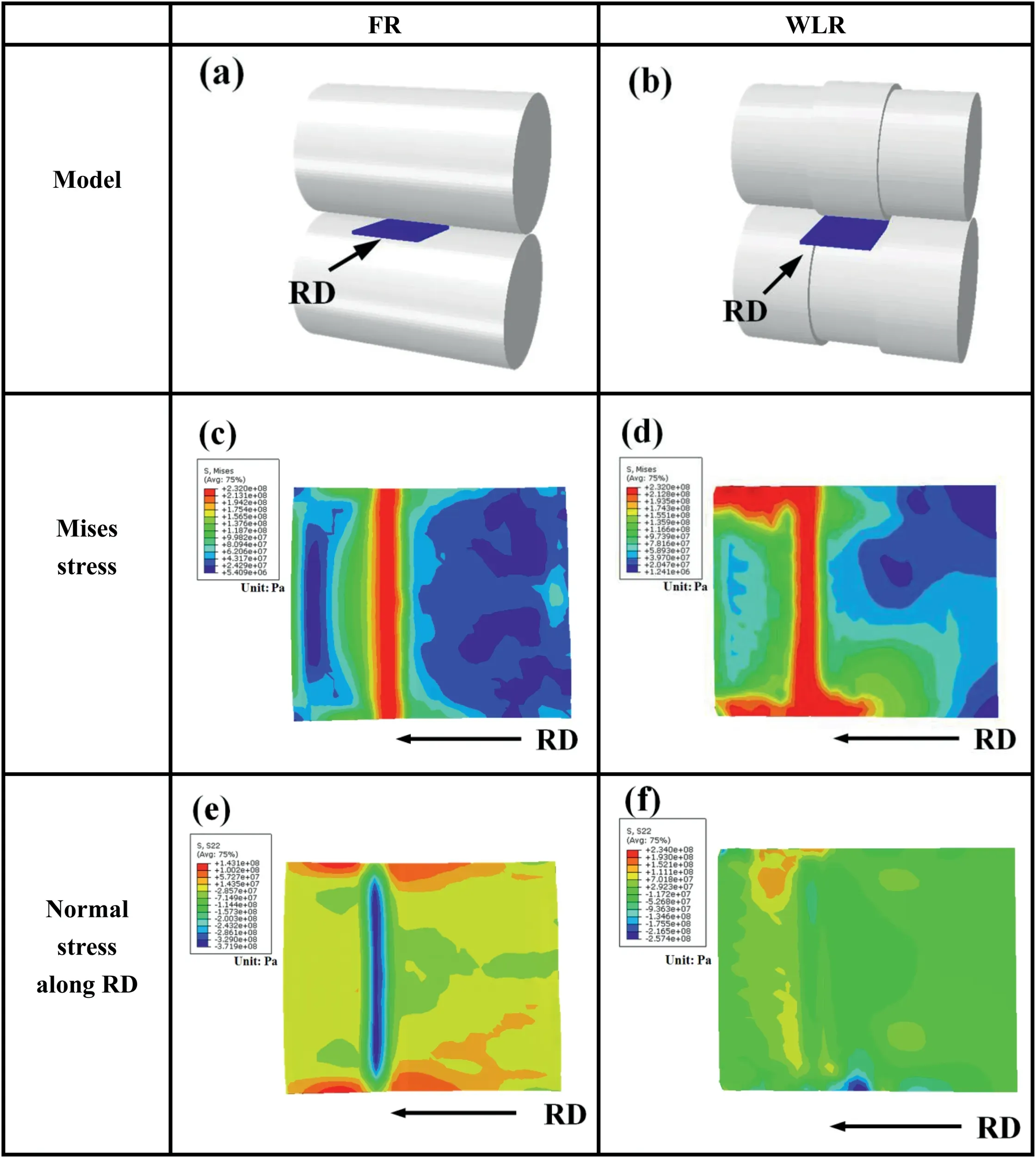
Fig.3.Abaqus model,Mises stress and normal stress along RD distribution of magnesium alloy sheet under FR and WLR.
3.2.Microstructure influenced by WLR
Because of the width limitation in WLR,the stress field of the sheet after WLR is different from the sheet after FR,which should result in different microstructures at the edge portion and the middle portion of the sheet after FR and WLR.Fig.4a andb shows the microstructure at the middle portion of the sheet after FR and WLR.There is little difference in structures in the middle of the sheet after FR and WLR,which are relatively uniform.The microstructures at the edge portion of the sheet after FR and WLR are shown in Fig.5a and b.The difference is mainly concentrated on the edge of the sheet.It is established that WLR has a more significant effect at the edge portion than at the central portion and acts mainly to change the stress field of the edge.
The microstructure at the edge of the WLR sheet compared to that of the FR sheet is further refined,with the grain distribution being relatively uniform and the grain boundaries being denser.There are a large number of dislocations and shear bands.The grain refinement of the FR sheet is attributed to shear deformation during the rolling process,while the uniformity of the distribution and the grain refinement of the WLR sheet is attributed not only to the shear deformation caused by rolling but also to the compressed stress caused by limiting broadening along with the TD.
The sheet after WLR contained a higher density of deformation twins due to more deformation than FR.A lot of laminated twins and cross twins are produced in Fig.5(e),(f),and(h),and some fine grains are observed in it,which may be double twins.Dynamic recrystallization tends to nucleate at the cross-twinned region [19-21].Twin intersections resulting from the stress field along TD has more energy to be potential nucleation sites for recrystallization [22-25],which will also lead to generating more recrystallization during subsequent annealing to make the basal texture weaken.It is meaningful for the formability of magnesium alloy.
There are many grain boundaries of high energy storage after WLR leading to more potential recrystallization nucleation sites in dislocations,as shown in Fig.5(g).Dynamic recrystallization can absorb a large amount of dislocation accumulation energy,which prevents the magnesium alloy from hardening during deformation and plays a strong softening role [26,27].Dynamic recrystallization reduces the grain size of the sheet and improves the strength and ductility of the magnesium alloy [28-31].
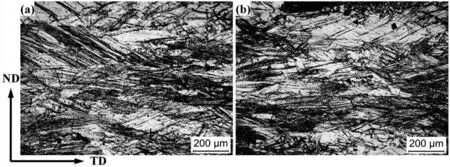
Fig.4.Optical images of the middle of AZ31 Mg alloy sheet after different rolling methods: (a) the sheet after FR;(b) the sheet after WLR.

Fig.5.Optical images of the edge of AZ31 Mg alloy sheet after different rolling methods: (a) the sheet after FR;(b,c) magnified view of the marked region in (a);(d) the sheet after WLR;(e,f,g,h) the magnified view of the marked region in (d).
During WLR,there is more dynamic recrystallization and more potential recrystallization nucleation sites at the edge of the sheet,which refines the grains,strengthens the structure,and absorbs the dislocation accumulation energy,weakening the work hardening.These changes should be beneficial to subsequent processing of the magnesium alloy sheet.
To further determine the twin type and dislocation type,explore the interaction between twins and dislocations,and found the effect of twin and dislocation on recrystallization nucleation sites,TEM and EBSD analysis were carried out.
3.3.TEM results
3.3.1.Twinning development
Fig.6 exhibits a bright-field TEM image with marks showing the feature of deformation twins near the edge part of the sheet after FR and WLR,in which the outlines of these deformation twins are denoted by the yellow dotted lines.There are many narrow strips and smaller twins in Fig.6(a),which have the same morphology as the rolled twins formed by conventional rolling and can be seen as typical compressive twins.Compressive twins always maintain a relatively fine morphology during deformation.The twins after WLR are maturely developed as shown in Fig.6(b).
Fig.7(a)is TEM image showing the feature of deformation twins near the edge part of the sheet after WLR.The outlines of these deformation twins are denoted by the yellow dotted lines.The twins are denoted by Ti (i=1,2,3) and the matrix is marked by Mi (i=1,2,3,4).Region 1,4,7,8 represent the matrix in different positions and region 5 represents T2.Region 2,3,6,and 9 are the grain boundaries between M1 and T1,T1 and T2,M2 and T2 as well as T3 and M3.There is the further development of twins and high-density dislocations,and dislocations also occur within the grains.
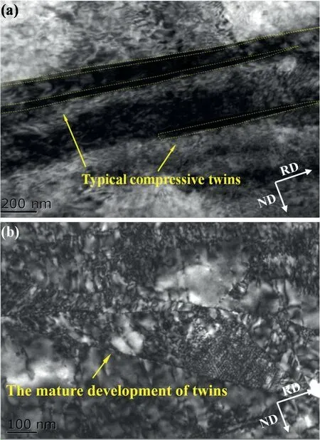
Fig.6.(a) Bright-field TEM image with a mark showing the feature of deformation twins near edge part of the sheet after FR;The outlines of these deformation twins are denoted by the yellow dotted lines.(b) TEM image with a mark showing the feature of deformation twins near the edge part of the sheet after WLR.(For interpretation of the references to colour in this figure legend,the reader is referred to the web version of this article.)
Fig.7(b-j) present the selected area diffraction patterns taken from the region 1,2,3,4,5,6,7,8,and 9.The electron beam is nearly parallel to the [2-1-10] zone axis.The twins are denoted by Ti (i=1,2,3) and the matrix is marked by Mi (i=1,2,3,4).T1,T2,and T3 are marked by blue,red and green lines.Mi (i=1,2,3,4) are marked by yellow.It is clear to see the orientation.
The angle between basal planes of M and T1 is measured as~56° in Fig.7(c),suggesting that T1 also satisfies {01}<012>compressive twinning orientation relationship.The angle between basal planes of T1 and T2 is measured as~86°,very close to the theoretical value of tensile twin (86.3°).The acute angle between basal planes of M and T2 is measured as~36°,suggesting that T2 also satisfies Fig.7(c),suggesting that T1 also satisfies {101}-{102}double twinning orientation relationship.Thus,double twin generally indicates {102} twin formed inside {101} twin,which has been frequently observed in the edge of the sheet after WLR.Fig.7(e) and (f) present the selected area diffraction patterns taken from the region marked T2 and M2,respectively.Fig.7(g)shows the misorientation between T2 and M2 is about 36°,which is also a double twin.It reveals that the further development of compressive twins to form double twins is easier to happen during WLR.T3 is obtained by M3 rotating about 56° around [20] in Fig.7(j).T3 and T1 are all compressive twins but they are in different directions,which mean twin variants are produced in WLR.
At the edge of the sheet after FR,the crack releases energy,so that the twin cannot fully develop,and only appears as a compressive twin.There is no crack on the edge of the sheet after WLR,the edge bear greater deformation,leading full development of compressive twinning.The grain orientation is favorable for double twinning deformation.{101}compressive twin occurs first,which is same as the sheet after FR and subsequently,{102} tensile twin occurs inside the {101} compressive twins,resulting in the formation of{101}-{102} double twins,which are considered a complex compressive twin.Compressive twins can coordinate the compression deformation of the c-axis and reorient the c-axis to 56°,which is conducive to texture weaken and subsequent tensile deformation.The compression twins mainly occur at the end of the deformation,which is conducive to stress relaxation.
3.3.2.The activation of slip system
The simple twin deformation will cause a large stress concentration with the surrounding matrix,which requires the cooperation of other deformation systems.Various types of dislocation slip systems in the twin and matrix can also be fully activated.Fig.7(h) shows the diffraction patterns of M4,which is a little different from M1 that is marked by the yellow dotted line in Fig.7(h).The slight angle is caused by the deformation of the grain and dislocation.It is also obvious that the orientations of M1,M2,M3,and M4 are not exactly in the same direction that slight deviation exists,which is caused by the dislocation slip of the matrix.
The HRTEM image in Fig.8 is showing the region marked red line in Fig.7(a).The electron beam is nearly parallel to[20] zone axis.The twins are denoted by Ti (i=2,3) and the matrix is marked by M3.Fig.8(b-d) exhibits the results of electron diffraction patterns taken from the regions marked M,T2,and T3,respectively.It shows that the misorientation between basal planes of M and T2,M and T3 equals to~57°and~44°.The actual misorientation (57°) between basal planes of M and T2 is almost equal to the theoretical misorientation of {10-11} twin (56.4°).It has been confirmed that T2 is a double twin.The ideal misorientation between T2 and M is about 38°,which is different from the actual angle (~44°).It is because deformation occurs and high-density dislocation forms inside double twins,leading the deformed part and undeformed part has a misorientation of about 6~7°
Fig.9(b-d)show different types of dislocation in the different color dotted lines in Fig.9(a)of M,T2,and T3 at the edge of the after WLR.They respectively represent the slip system of the matrix,the double twin,and the compressive twin.The arrows denote the position of the dislocation.It demonstrates that basal<a>slip,prismatic<a>slip,pyramidal<a>slip and pyramidal<c+a>slip are activated in the matrix and inside the double twin and the compressed twin,especially the pyramidal<c+a>slip.Due to the higher rolling temperature of 400°C,pyramidal<c+a>slip is activated,which can coordinate the strain of the c axis.
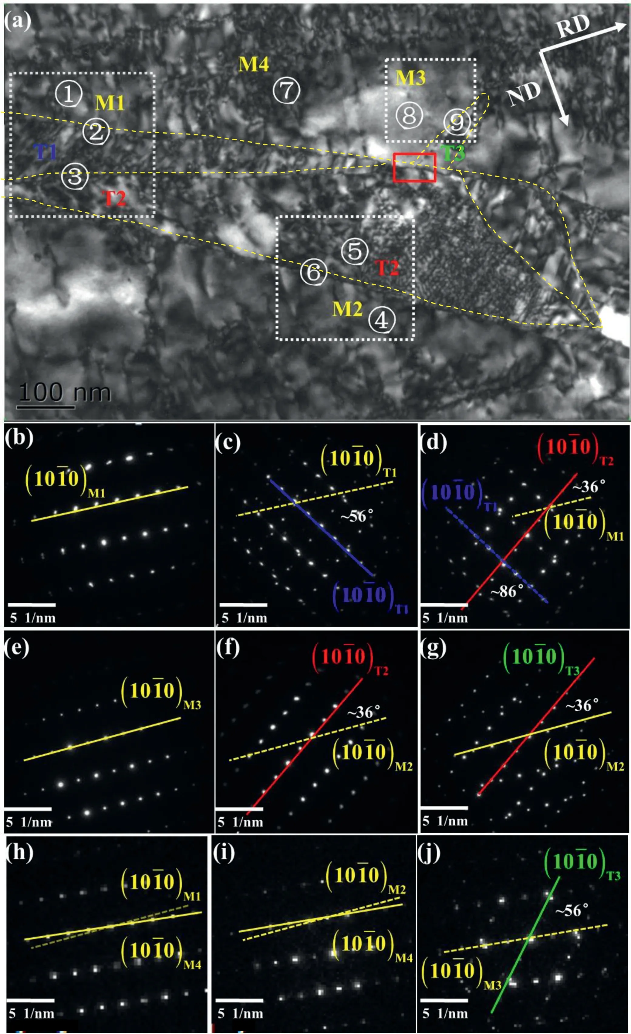
Fig.7.(a) TEM image with a mark showing the feature of deformation twins near the edge part of the sheet after WLR.The outlines of these deformation twins are denoted by the yellow dotted lines.The twins are denoted by Ti (i=1,2,3) and the matrix is marked by Mi (i=1,2,3,4).Region 1,4,7,8 represent the matrix in different positions and region 5 represents T2.Region 2,3,6,and 9 are the grain boundaries between M1 and T1,T1 and T2,M2 and T2 as well as T3 and M3.(b-j) The diffraction patterns are taken from region 1,2,3,4,5,6,7,8,and 9.The electron beam is nearly parallel to the[2-1-10] zone axis.The twins are denoted by Ti (i=1,2,3) and the matrix is marked by Mi (i=1,2,3,4).T1,T2,and T4 are marked by the blue,red,and green lines.Mi (i=1,2,3,4) are marked by yellow line.(For interpretation of the references to colour in this figure legend,the reader is referred to the web version of this article.)
WLR makes the sheet undergo greater deformation,which leads to the further development of twins.To coordinate the stress concentration caused by twins,the slip system is completely activated.The slip system not only coordinated the deformation between the matrix and the twins but also generated dislocations inside the twins.The cooperation of twins and dislocations greatly improves the plasticity of rolled magnesium alloy sheets and reduces the tendency to crack.

Fig.8.(a) HRTEM image showing the region marked red line in Fig.7(a);The electron beam is nearly parallel to [2-1-10] zone axis.The twins are denoted by Ti (i=2,3) and the matrix is marked by M.(b,c,d) The selected area diffraction patterns taken from the regions M,T2,and T3.(e,f,g) The misorientation of M,T2,and T3.(For interpretation of the references to colour in this figure legend,the reader is referred to the web version of this article.)
3.4.EBSD analysis
3.4.1.Misorientation angles
Fig.10 is EBSD results and Fig.10(a) and (b) show the microstructure and texture of the as-received sheet.It can be observed in Fig.10(a) that the as-received sheet exhibits a coarse grain and a strong basal orientation.The (0001) pole figure (Fig.10b) reveals a typical basal texture with c-axis// ND.Strong basal texture during rolling,resulting in poor plastic formability [32].Weakening or changing the strong basal texture is an effective way to improve the formability of rolled magnesium alloys [33].
Fig.10(c) and (e) show that the grains after FR and WLR are fined by twins to some extent.The grain boundaries after WLR is denser compared to that after FR,and the original grains are divided into tiny grains because of the twin laminates,which contributes to refining grains.Refinement in the microstructure has been attributed to compressive strain during rolling,along with the shear strain produced.The stress field of the WLR sheet is more complex than that of the FR sheet,leading to more refined grains with a more uniform distribution.Twinning also can generate a large of twin boundaries to influence the mechanical properties of magnesium alloys.
Fig.10(d) and (f) shows the misorientation angles after FR and WLR,respectively.There are three peaks around 38°,56°,and 86°,which represent {101}-{102} double twins,{101} compressive twins,and {102} tensile twins,respectively.The highest peak in Fig.11(d) is {102} tensile twins,which can reorient the basal plane by 86° and {101}-{102}double twins is almost rarely.However,it can be seen in Fig.10(f) that after WLR,the misorientation angle distribution was more uniform and the intensities of the peaks that present three kinds of twins changed.Peaks of tensile twins are slightly reduced and peaks of compressive twins and double twins are increased,especially double twins.This again shows that it is easily generated during WLR that tensile twin occurs inside compressive twin,which means compressive twins convert to double twins.
Tensile twinning takes place under tensile load parallel to the c-axis of grain or under compression load perpendicular to the c-axis.It can be inferred that WLR restricts the deformation in TD,leading the sheet under compression in TD,will make more tensile twins,which is contrary to reality that the tensile twins of WLR slightly decreased.Maybe a transition from tensile twins to compressive twins has occurred.Moreover,when the deformation temperature is higher than 250°C,a large amount of starting slip will inhibit the occurrence of {102} tensile twins.The {101}-{102} double twins generated by the {101} compressive twins are easily observed when the temperature is higher than 300°C [34-37].Rolling temperature is 400°C,which is a reason that WLR made tensile twins slightly decreased and double twins significantly increased.

Fig.10.EBSD results of samples:(a,b)The IPF and pole figures of the as-received sheet;IPF and Distributions of grain misorientation angle of the samples after different rolling methods: (c,d) FR;(e,f) WLR.
Fig.11 is EBSD results of magnified view of the region marked with black line in Fig.10(e).It can clearly show the orientation relationship between twins and its influence on the texture.Boundaries of {102},{101} and{101}-{102} twins are colored in red,green and yellow.The theoretical angle/axis for these three types of twins are 86.3<110>,56.2°/<110>and 38.5°/<110>,respectively [38].Fig.11(c) shows the line profiles for the misorientation angle along the direction indicated by the white arrow and black arrow in Fig.11(a).Black point-to-point represents the misorientation angle along the black arrow and red point-to-point represents the misorientation angle along the white arrow.Obviously,the black point-to-point profile shows that the misorientation angles across the twin boundaries colored in green and red are approximately equal to 55.4° and 86.7°,almost consistent with the ideal {101} and{102} twins.The red point-to-point profile shows that the misorientation angles across the twin boundaries colored in yellow are approximately equal to 38.9°,almost consistent with the ideal {101}-{102} double twins.It reveals that{101}-{102}double twins is generated by producing{102}tensile twins inside {101} compressive twins.Their orientation relationship is shown in the (0001) pole figure,as shown in Fig.11(d).It also shows that twinning can make grains to rotate to tailor the texture.
3.4.2.Recrystallization
Fig.12 shows the comparison of recrystallized grains,subgrains,and deformed grains content of FR and WLR and its distribution.There are more recrystallized grains and deformed grains after WLR.It can be seen from Fig.12(c) that deformed areas are around the twin intersections and dynamically recrystallized are near large deformation areas.

Fig.11.Typical EBSD results of a magnified view of the region marked with a black line in Fig.10(e).(a) inverse pole figure map and (b) the results in band contrast;Boundaries of {10-12},{10-11}and {10-11}-{10-12} twins are colored in red,green and yellow.(c) Line profiles for the misorientation angle along the direction indicated by the white arrow and black arrow in Fig.11(a);Black point-to-point represents the misorientation angle along the black arrow and red point-to-point represents the misorientation angle along the white arrow (d) (0001) pole figure.(For interpretation of the references to colour in this figure legend,the reader is referred to the web version of this article.)

Fig.12.(a) Comparison of recrystallized,substructued,and deformed grains content of FR and WLR;Recrystallized grain distribution of the samples: (b)FR (c) WLR.
Due to the greater deformation of the sheet in WLR,the denser twin grain boundaries and high dislocation density have high energy and are more conducive to recrystallization nucleation.Combined with Fig.5,the sheet after WLR with more high-density dislocations and intersectional twins of high energy storage has more recrystallized grains and more potential recrystallization nucleation sites at the edge of the sheet,which refines the grains,strengthens the structure,and absorbs the dislocation accumulation energy,weakening the work hardening,and also will lead to generating more recrystallization during subsequent annealing to make the basal texture weaken [26,30,31].
3.4.3.Schmid factor
Figs.13 and 14 give the Schmidt factor distributions of {0001}<110>,{100}<110>,and {112}<11>slip systems after different rolling modes.The Schmidt factors of the three slip systems after WLR increased,especially that of the {100}<110>slip system.
For the FR sheet,the Schmidt factor of the basal slip and the cylinder slip is small,so most of the grains are in hard orientation.For the {100}<110>slip system,the average Schmidt factor of FR is only 0.19.So plastic deformation of magnesium alloy under FR mainly depends on the coordinated movement of basal slip and twins;the basal slip can only provide two independent slip systems and pyramidal slip is usually difficult to activate at room temperature [40],which is not conducive to subsequent tensile deformation,leading poor mechanical properties.
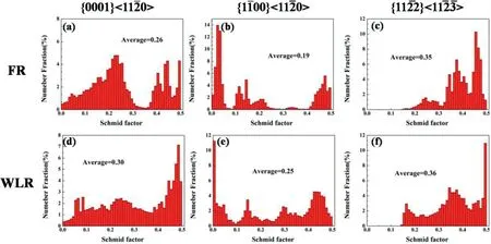
Fig.13.Distributions of Schmid factor of the samples: (a,b,c) FR;(d,e,f) WLR.
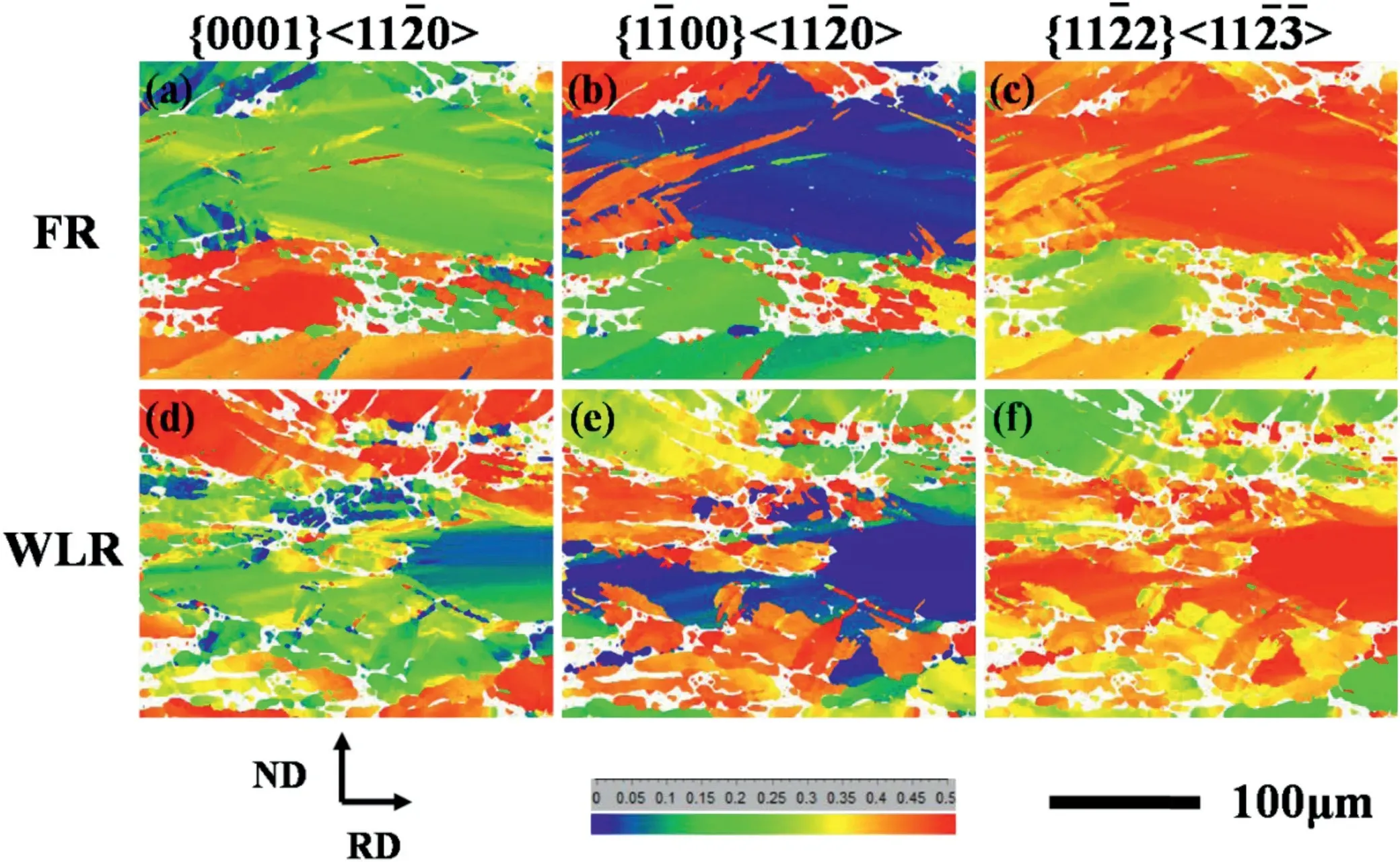
Fig.14.SF maps of the samples: (a,b,c) FR;(d,e,f) WLR in Fig.9.
The Schmidt factor for the {100}<110>slip system of the WLR sheet is approximately 0.25,which is greatly improved over that of the FR sheet,as shown in Fig.13(e).Combined with SF distribution in Fig.14(e),it is found that deformed fine grains possess higher SF than undeformed coarse grains.This indicates that thin twin laminates can change the orientation of grains,which is beneficial to change the hard orientation to the soft orientation.The activation of the slip system also can coordinate the strain of deformation between grains and the subsequent tensile deformation,promoting the plastic deformation of Mg alloy and resulting in the improvement of plasticity after WLR,as shown in Fig.16.
Compared with FR sheets,the Schmidt factor of basal<a>slip,prismatic<a>slip,and pyramidal<c+a>slip is increased,especially prismatic<a>slip,which is easier to start at room temperature to coordinates the strain [41] and conductive to the plasticity.
3.5.Texture
In order to further explore the effect of WLR on the texture and the effect of the twins on the texture,the macrotexture of the rolled sheet after FR and WLR was measured using XRD.The results are shown in Fig.15.
After FR,the texture changes with the formation of new orientations and the basal texture are strengthened in Fig.16(a).The basal texture strengthening is not conducive to subsequent processing and plastic deformation.The {102}twins of the sheet after FR caused grains to rotate by 86° and made the texture changed to generate more texture component parallel to TD.
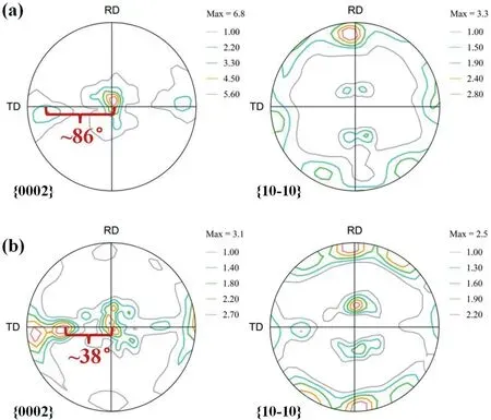
Fig.15.Pole figures of samples measured by XRD: (a) the rolled magnesium alloy sheet after FR;(b) the rolled magnesium alloy sheet after WLR.

Fig.16.(a) Engineering stress-strain curve under tension along TD of AZ31 rolled plate and SEM images of tensile fracture surfaces of samples after different rolling methods: (b) FR;(c) WLR.
WLR has caused the weakening of the texture and produced a double texture parallel to the TD.After WLR,the grain orientation of the sheet is more random and is changed from a hard orientation to a soft orientation,weakening the basal texture,which is beneficial for coordinated deformation[42-44].The basal texture weakening significantly reduced inplane anisotropy,thus improving formability [45-48].Double twins caused the~38° lattice rotation and generated a new texture component in Fig.15(b).The c-axis of the grains after WLR is inclined by approximately 38° from the ND to the TD.The tilt of the c-axis and the weakened texture are beneficial to basal slip during the plastic deformation process,which helps to improve the mechanical properties and the total elongation.Therefore,WLR is beneficial to plastic deformation.
3.6.Mechanical properties
Fig.16(a) shows the tensile curves of magnesium alloy sheets along with the TD after FR and WLR,respectively.It can be seen that both the tensile strength and total elongation of the magnesium sheet are improved after WLR compared to that after FR,with tensile strength increasing from 244 to 250MPa and total elongation increasing from 12.60% to 17.11%,respectively.Although the increase is not very significant,the simultaneous improvement in strength and total elongation is valuable,indicating that WLR has a certain effect on improving the mechanical properties of magnesium alloys.
Tensile fracture of magnesium alloy sheets after FR and WLR along the TD is shown in Fig.16(b) and (c).Compared with the large dimples in Fig.16(b),obvious smaller dimples can be seen in Fig.16(c).The appearance of the small-size dimples indicates that the sheet after WLR has better plasticity.Moreover,dimples on the fracture of the sheet after WLR exhibit a uniform size and an even distribution.
Complex stress field of the sheet during WLR that the shear deformation caused by rolling and the compressed stress caused by limiting broadening along the TD lead the uniformity of the distribution and the grain refinement.Uniform microstructures reduce the edge crack tendency.The grain refinement and twin boundaries have a good effect on tensile strength.The cooperation of dislocation slip and twin deformation leads to plasticity improvement.WLR can weaken basal texture and improve anisotropy,which is beneficial for coordinated deformation.WLR changes grain orientation from a hard orientation to a soft orientation,which has a higher Schmidt factor,leading to the improvement of plasticity.
4.Conclusion
1.WLR,in which the width of the alloy sheet is limited during rolling,is applied to a magnesium alloy sheet.The width limitation is realized by modification of the shape of the rollers,so that a compressive stress field forms at the edge portion of the alloy sheet during rolling,which reduces the tensile stress along RD,leading to the reduction of the edge cracks.
2.WLR bears greater deformation without edge cracks,leading to mature development of compressive twinning to form double twins and accumulation of high-density dislocation to activate the slip system.With the development of twinning and various types of slip systems in the twin and matrix,the texture of the sheet after the width-limited rolling is weakened and the plasticity of the rolled sheet is improved.
3.The grain orientation after WLR changes from hard orientation to soft orientation and twins reorient the basal plane,leading to basal texture weakened.The sheet after WLR has more twin intersections and shear bands,providing more potential recrystallization nucleation sites,which are also beneficial to weaken basal texture.WLR weakens the basal texture,resulting in a significant increase in the plasticity of the sheet.
4.WLR not only effectively suppresses the edge cracking tendency of AZ31 magnesium alloy during rolling but also improves the rolling forming performance of the magnesium alloy.Compared with FR,the simultaneous improvement in strength and elongation is especially valuable,which indicates that WLR has a certain effect on improving the mechanical properties of magnesium alloys.
Declaration of Competing Interest
None.
Acknowledgments
This study was supported by National Natural Science Foundation of China under Grant Nos.U1810208,51474152 U1710254 and 52 005362;Shanxi province science and technology major projects under Grant No.20181101008.
杂志排行
Journal of Magnesium and Alloys的其它文章
- Improving the Young’s modulus of Mg via alloying and compositing -A short review
- Surface modifciation of magnesium alloys using thermal and solid-state cold spray processes: Challenges and latest progresses
- Preparation,structure and properties of Mg/Al laminated metal composites fabricated by roll-bonding,a review
- A review on recent advancements in biodegradable Mg-Ca alloys
- Analysis of element loss,densification,and defects in laser-based powder-bed fusion of magnesium alloy WE43
- Pore structure of porous Mg-1Mn-xZn alloy fabricated by metal-gas eutectic unidirectional solidification✩
