Analysis of element loss,densification,and defects in laser-based powder-bed fusion of magnesium alloy WE43
2022-10-25FaridrezaAttarzadehEbrahimAsadi
Faridreza Attarzadeh,Ebrahim Asadi
Department of Mechanical Engineering,The University of Memphis,Memphis,TN 38152,United States
Abstract It is well known that laser-based powder-bed fusion (L-PBF) additive manufacturing of magnesium (Mg) and its alloys is associated with high Mg loss due to vaporization (MgLoss) and high incidence of many types of defects in the manufactured parts/samples.Despite this,MgLoss,densification,and defect characteristics have not been holistically considered in the determination of the optimal values of L-PBF processing parameters for Mg and its alloys.This study presents a combined modeling and experimental approach applied for a widely used Mg alloy (WE43) to address this shortcoming in the literature.First,an experimentally calibrated model is proposed to determine MgLoss as a function of the L-PBF processing parameters.The model couples the temperature profile using a double ellipsoidal heat source with a Langmuir vaporization model and is calibrated using the width of the single-track L-PBF process and the measured Mgloss using inductively coupled plasma mass spectrometry (ICP-MS).Second,the densification of the samples is determined using a modification of the Archimedes method that considers the amount of MgLoss in the calculation of the relative density.Third,a comprehensive and quantitative study is conducted on the relationships between the characteristics of porosity defects and the L-PBF processing parameters.Finally,the optimized L-PBF processing parameters are determined by considering the MgLoss,densification,and the characteristics of defects.The present study yields 0.23 wt.% MgLoss compared to 2 wt.% MgLoss that was reported in the previous studies.Furthermore,more than 99.5% densification is achieved while only~2% and~0.5% of the total defects are characterized as keyhole and lack of fusion defects,respectively.
Keywords: WE43 magnesium alloy;Additive manufacturing;Powder-bed fusion;Mg loss;Vaporization;Defects.
1.Introduction
Magnesium (Mg) and its alloys are used to fabricate a wide variety of components and structures because of their many attractive properties,notably high strength-to-weight ratio,high damping factor,easy recyclability,and excellent electromagnetic interference shielding [1-4].Additive manufacturing (AM) of Mg and its alloys is in its infancy compared to many successful uses of this technology to fabricate parts of several other metallic materials,such as stainless steels,tool steels,Ti-6Al-4V,Hastelloy,Inconel,CoCrMo alloy,AlSi10Mg alloy,W,and Ta [5].Although the AM processes that have been used to manufacture Mg and its alloys also include wire-arc AM and friction stir AM [6-12],the focus of the present study is on the laser-based powderbed fusion (L-PBF) process.The basic L-PBF processing parameters include laser power (P),scanning speed (v),hatch spacing (h),and layer thickness (t).Other related L-PBF processing parameters are the laser focal area diameter (d) and the type and flow characteristics of the inert gas used during the process to minimize oxidation.The energy density is defined asE=p/vhtin most PBF studies.The normalized definition of the energy density () is also used for comparative discussions of L-PBF processing with different lasers and different materials;see Eqs.(8-9) for the definition and Ref.[6].Often,these L-PBF processing parameters and the energy density are optimized initially to achieve full densification followed by additional alloy modification,processoptimization,and/or post-AM thermal/mechanical processing to achieve other desired properties.However,this initial task has been proven cumbersome for L-PBF processing of Mg and its alloys due to several factors related to the extensive vaporization of Mg during the process because of the narrow temperature range between the melting and boiling points of Mg (650-1107 °C) [7].Besides,the vapor pressure of Mg increases from 0.13 kPa at 620 °C to 51 kPa at 1027 °C further contributing to the vaporization.Another contributing factor is the high oxidation tendency of Mg powder that tends to react with even small amounts of oxygen present as an impurity in the argon gas to form MgO at temperatures above 400 °C[8].Consequently,the high oxidation level of Mg makes the processability of this material more challenging because of the high melting point of MgO,requiring higher laser powers to melt the powder,resulting in increased vaporization.
Compared to the L-PBF processing of pure Mg [9] and other Mg alloys such as Mg-9Al [10],AZ91D [11],Mg-5.2Zn-0.5Zr alloy (ZK60) [12,13],Mg-11.00Gd-1.77Zn-0.43Zr (GZ112K) [14],Mg-4Y-3RE alloy (WE43)has received considerably more attention.Perhaps,the laser weldability of WE43 alloy has contributed to this attention.Furthermore,WE43 alloy offers a range of other interesting properties such as high mechanical strength,castability,hot formability,high corrosion resistance,and biocompatibility.The first study on the L-PBF processing of this alloy was reported by Tandon et al.[15] in 2015.They used process parameters ofP=20-100 W,v=200-10,000 mm/s,h=0.015-0.12 mm,t=0.05 mm,andd=0.07 mm and achieved less than 1% porosity.Bar et al.[16] utilizedP=200 W,v=700 mm/s,h=0.04 mm,t=0.03 mm,andd=0.125 mm for L-PBF processing of WE43,reporting 99.9% relative density.The corresponding calculated energy density for this set of L-PBF processing parameters is=50.36.In another L-PBF study by Gangireddy et al.[17],they were able to lower the porosity to 0.3% using L-PBF process parameters ofP=195 W,v=800 mm/s,h=0.20 mm,t=0.03 mm,andd=0.1 mm,resulting in=8.59.However,their image analysis results showed that the same sample had 0.4% porosity.Zumdick et al.[18] used the L-PBF processing parameters ofP=200 W,v=700 mm/s,h=0.04 mm,t=0.03 mm,andd=0.125 mm,resulting in=50.36.Their chemical composition analysis revealed that there is a 2 to 4% Mg loss(MgLoss)and a relative increase in the contents of the alloying elements.Esmaily et al.[19] determined the process map for L-PBF of WE43 alloy withP=40-400 W,v=200-2000 mm/s,h=0.04 mm,t=0.03 mm,andd=0.09 mm.They concluded that a laser power of 300 W and scanning speed of 1200 mm/s,corresponding to=44.07,results in a sample with 99.5% relative density and a negligible fraction of defects.
More recently,Hyer et al.[20] conducted a feasibility study of L-PBF placement of the single-tracks on wrought WE43 substrates followed by a parametric study on the L-PBF processing parameters optimization.They utilizedP=100-250 W,v=100-1600 mm/s,t=0.04 mm,h=0.13 mm,andd=0.07 mm in their parametric study.They determined the energy density range ofE=32-37J/mm3as a suitable processing window to achieve relatively high densifications,corresponding to the relative densities higher than 99%.Nevertheless,they identifiedP=200 W andv=1100 mm/s,corresponding to=9.86,as L-PBF processing parameters that simultaneously result in higher than 99% relative density and less than 1% defects when defects volume was measured by optical microscopy combined with image analysis.Furthermore,they noted relative densities of more than 100% in some of the samples.This may be explained by considering the MgLossand its influence on the ideal density of the alloy that was used for the calculation of the relative density.The ideal density of WE43 alloy based on the nominal chemistry of this alloy is calculated as 1.825 g/cm3that appears to be the ideal density used for the relative density calculations in most L-PBF studies discussed here.Considering the MgLossof 2% (e.g.WE54) due to the severe vaporization in the L-PBF process,the ideal density is calculated as 1.851 g/cm3that is 1.42% higher than the nominal density of the WE43 alloy.This difference may explain the reported above the 100% relative densities by Hyer et al.Nevertheless,the reported optimalfor L-PBF processing of WE43 alloy in literature is~8-12.5 and the possible correlations of L-PBF processing parameters with MgLossand porosities have not been comprehensively investigated.
The purpose of the present study,which is in three parts,was to address these shortcomings of the literature,concerning L-PBF processing of WE43 alloy.In a preliminary study(the main points of which are summarized in the present report),a design-of-experiment (DoE) method,Taguchi,was used to determine the ranges of four L-PBF process parameters (P,v,h,t) that are postulated to result in very high densification of manufactured samples (>98%).Based on the results of the preliminary study,16 sets of the process parameters were selected for use in the work conducted in the three parts of the study.In the first part,the Langmuir vaporization model was combined with a three-dimensional (3D) temperature model of the L-PBF process to yield a Multiphysics model to calculate MgLoss.The model was calibrated using the width of the single-track L-PBF processing and MgLossexperimentally obtained using inductively coupled plasma mass spectrometry (ICP-MS).Then,the calibrated model was used to obtain empirical relationships between MgLossand each of the process parameters.The second part of the study was dedicated to the experimental determination of the densification of the 16 samples manufactured using the ranges of process parameters and the best-fit empirical relationship between densification of the samples andE.The third part of the study involved a detailed quantitative characterization of the defects in the 16 samples.A method is utilized to classify the defects as keyhole (KH) or lack of fusion (LF) based on their sphericity/size and their correlations with the L-PBF processing parameters are studied.Finally,the optimized L-PBF processing parameters considering the MgLoss,densification,and characteristics of defects is presented.
2.Materials and methods
2.1.Modeling methods
In this sub-section,the model and the experimental calibration method used to determine the MgLossand vaporization during the L-PBF process are presented.The Langmuir model is commonly used to describe the maximum vaporization rate in laser welding of metal alloys [14,21,22]

where Jiis the vaporization rate of element i in the alloy(g·cm-2·s-1),βis an empirical correction factor,γiis the activity of element i in the alloy,χiis the molar fraction of element i in the alloy,Pi0is the standard pressure of the pure element i (Pa),Miis the molecular weight of the element i (g/mol),and T is the temperature (K).During the L-PBF process,a micron-scale melt pool is formed and the thermodynamic behavior of the molten alloy resembles that of an ideal solution;thus,the activity coefficient of each element can be assumed to be 1 [23].Moreover,PMg°(mmHg) is given as a function of temperature [24]

Fig.1 shows the variations of the Mg vaporization rate(JMg) and the ratio of JMgto the vaporization rate of Y,Nd,and Zr (the relative evaporation rate) with temperature,as calculated using Eqs.(1) and (2).JMgincreases rapidly atT≥1200 K (Fig.1a).The profile of each of the determined relative vaporization rates shows the dominant role of Mg in vaporization.As such,hereafter,the vaporization of the other alloying elements and the mass loss due to their vaporization were ignored.
The final weight concentration of the element i after processing is calculated thus

where V is the melt pool volume,ρis the density of the alloy,Wiis the initial weight concentration of element i,andΔmiis the amount of vaporized element.Δmiis calculated thus[25,26]

where Asis the top surface area of the melt-pool and t is the time step.
Several computational and experimental methods have been developed to determine the temperature profile of the material during the L-PBF process [27].In the present work,the analytical solution of a moving laser spot size on a halfinfinite domain,as determined by Fachinotti et al.[28] and Mirkoohi et al.[29],was used.This model assumes an experimentally-verified double ellipsoidal moving heat source to model the laser input energy [30] and uses Green’s function solution to solve the temperature profile of the melt-pool.That is
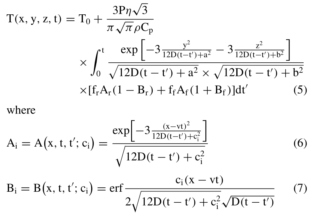
andT0is the powder bed temperature,p is the laser power,vis the scanning speed,t is the time,n is the laser absorptivity,Cpis the specific heat of the liquid metal,D is thermal diffusivity of the metal,and a,b,ciare heat source parameters.In Eqs.(6),and (7),the subscriptican be replaced by f or r,denoting the front and rear of the moving melt pool,respectively,while cfand crare the radii of the front and rear of the ellipsoid,respectively,and ffand frare the proportionality coefficients of the front and rear quadrants,respectively (Note that ff+fr=2).Considering the volumetric continuity of the heat source,yields ff/cf=fr/crand ff=αcf/(cf+cr).It was assumed thatα=3,which led to the choices of ff=0.6 and fr=1.4 [29,30].
Table 1 lists all the thermophysical parameters in Eq.(5) that were used in this study.The heat source parameters,a and b,were used to calibrate the model based on experimental data.These parameters were determined by comparing the analytically calculated melt-pool geometry to its experimentally measured counterpart fabricated as a singletrack in the L-PBF process.ForP=160 W andv=900-1125 mm/s,the melt-pool geometries for WE43 alloy have been experimentally measured by Hyer et al.[31].Using these L-PBF process parameters,the heat source parameters were determined asa=0.0002 andb=0.0001 m.For example,Fig.2 shows the XY,YZ,and XZ heat maps and contour plots of the weld pool corresponding to the top,side,and front view of the melt-pool,respectively,forP=160 W andv=900 mm/s.The melt-pool boundaries were determined using the isotemperature curves equal to the melting temperature of the alloy asT=813 K.

Table 1Thermophysical and laser parameters for the L-PBF process of WE43 alloy used in the present study.
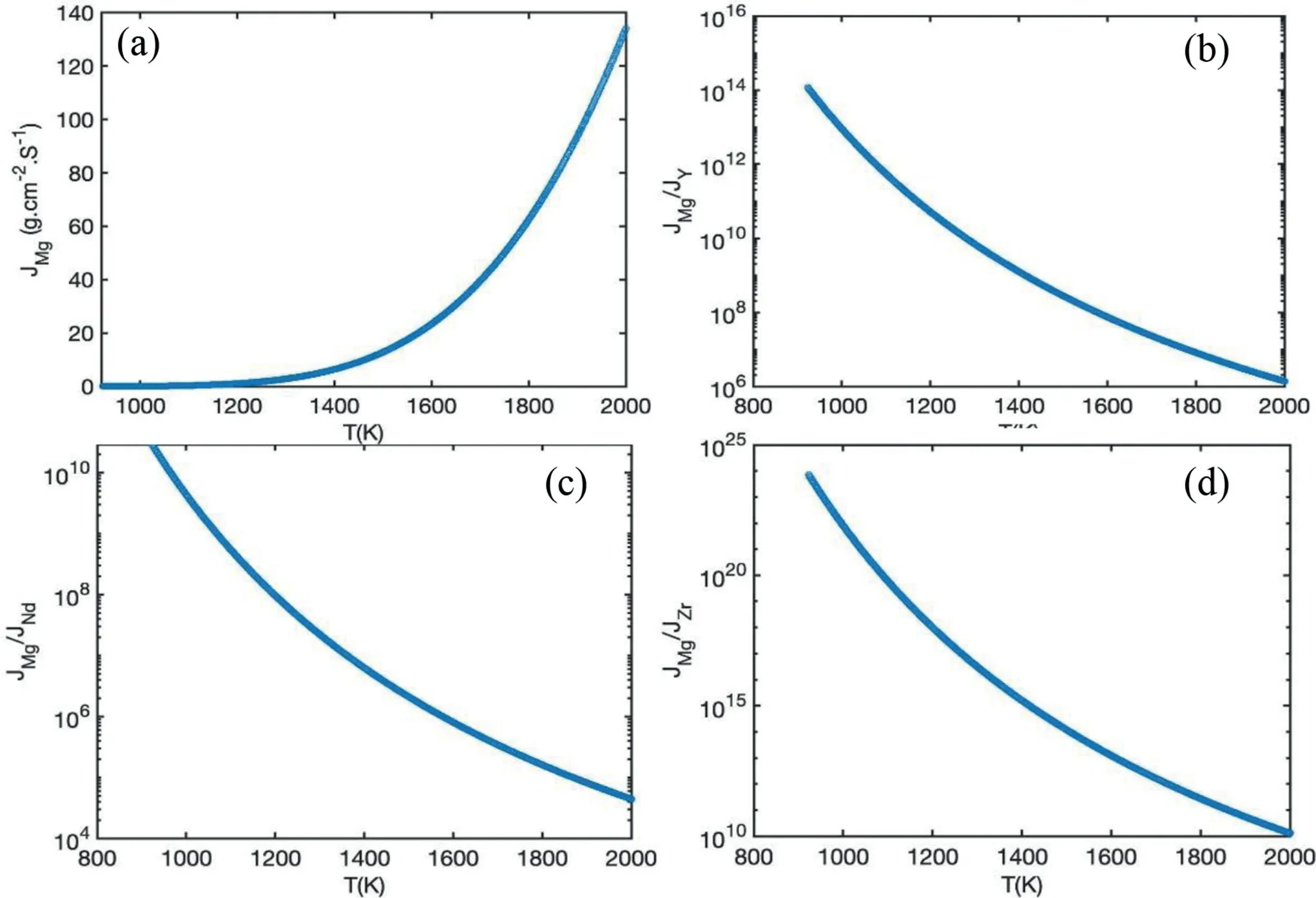
Fig.1.Variations of the Mg vaporization rate and vaporization ratios with temperature,using the Langmuir model: JMg (a),JMg/JY (b),(c) JMg/JNd (c),and JMg/JZr (d).

Fig.2.The temperature profile of WE43 alloy during the single-track L-PBF process using P=160 W and v=900 mm/s: top view on XY plane (a),middle side view (parallel to a deposition track) on an XZ plane (b),middle section transverse to a deposition track on a YZ plane (c),and the variation of the temperature along the track direction (d).On (a)-(c),solidus,liquidus,and boiling isotemperature curves are also shown.
Substituting the numerically calculated temperature profile from Eq.(5) into Eq.(1) and substituting the result into Eqs.(4) and (3) yields the MgLossand post L-PBF process weight concentration of Mg,respectively.
2.2.Experimental methods
Gas-atomized WE43 alloy powder (Elektron R○MAP+43)was used for manufacturing the samples.The physical char-acteristics of this powder (Table 2) were as given in the datasheet provided by the manufacturer.

Table 2 Physical properties of the WE43 alloy powder.

Fig.3.SE images of the powder at 200X magnification (a) and an individual powder particle at 1500X magnification (b) along with the colored EDS maps of the matrix and the major observed elements in the same particle (c-f).
To perform microstructural analysis of the powder,a field emission scanning electron microscope (FE-SEM) equipped with an Oxford energy-dispersive x-ray spectroscopy (EDS)system (Nova Nao 65) was used.Fig.3 shows the secondary electron (SE) images of the powder at 200X magnification(top left top) and an individual powder particle at 1500X magnification (bottom left),respectively.The acquired EDS mapping of that individual powder is presented on the right side of Fig.3.The observed powder particle sizes and the chemical composition are consistent with the nominal chemistry of the powder.The powder particles were spherical,with a few agglomerated,elongated,and satellited particles.
A metal AM machine (EOS M 100,EOS GmbH),with a building envelope of Ø 100 mm × 95 mm,was used to build cuboid samples,with dimensions of 10 mm×10 mm×15 mm.This machine is equipped with an Nd:YAG laser source,operating at a maximum power 200 W,and has a laser spot size of~40 μm in diameter.The build chamber was continuously flooded with argon gas (5.0 purity) until an oxygen level of 0.1% was reached.The stripe scan strategy was adopted with a layer rotation of 67° and a stripe length of 5 mm.The as-built samples were cut using wire electrical discharge machining (WEDM) for characterization.The manufacturing was performed in the Metal Additive Manufacturing Laboratory (The University of Memphis,Memphis,TN,USA),where the temperature and humidity are kept constant at 23 ± 3 °C and 30 ± 5%,respectively.
Table 3 lists the sample nomenclature and the corresponding L-PBF process parameters.Details of the preliminary study that was conducted to determine the collection of LPBF process parameters that was postulated to result in densification>98% for each sample are given in the Appendix.The preliminary study,in which two L25Taguchi DoEs were used,is based on comprehensive densification and defect analyses.
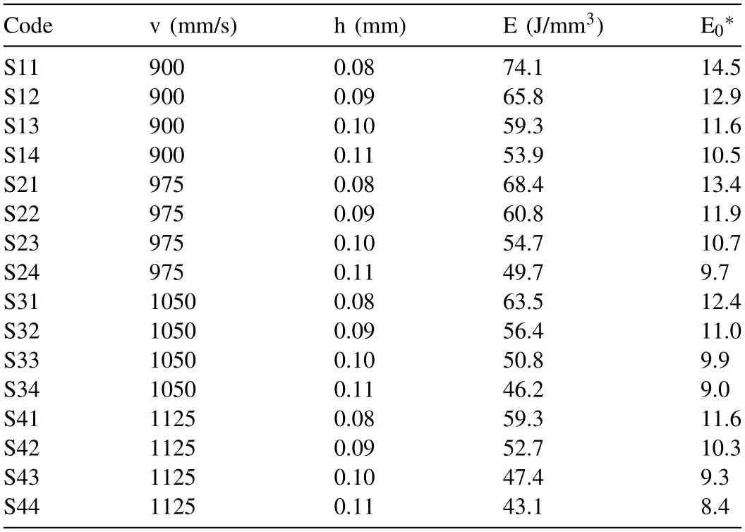
Table 3 List of L-PBF process parameters which were used in the present study.For all the samples, P=160 W and t=0.03 mm.
Since various L-PBF systems with different d values have been utilized for the fabrication of Mg and its alloys,it is nowcommon to normalize the process variables,leading to dimensionless values of laser beam power(P∗),scanning speed(v∗),hatch spacing (h∗),layer thickness (t∗) (and,hence,volumetric energy density () [27,28],which are defined thus:

In Eq.(8),ηis the surface absorptivity or coupling coefficient,rBis the laser spot radius (m),λis the thermal conductivity of the alloy (Wm-1K-1),αis the thermal diffusivity of the alloy (m2s-1),Tmis the melting temperature of the alloy (K),and T0is the powder bed temperature (K).Although for most materials,h is between 0.3 and 0.8,Mg and its alloys have low surface absorptivity [32].Thus,in the study,ηwas assumed to remain constant at 0.3.Assuming identical thermal properties of the powder bed and the fully dense material [6],the thermal conductivity of the alloy was calculated thus [33]

where Cpis the specific heat capacity of the alloy(J Kg-1K-1) andρris the powder bed relative density (kg m-3).The values of all the process variables used in the work are listed in Table 3.
The chemical compositions of these 16 samples were also analyzed using inductively coupled plasma mass spectrometry (ICP-MS) on a PerkinElmer 300X,outfitted with a glass nebulizer and spray chamber,and operated in kinetic energy discrimination (KED) mode with He collision gas.Samples were first digested in a mixture of 48 mL of ultrapure water and 2 mL of concentrated Nitric acid (HNO3).Then,20 mL of hydrofluoric acid(HF)was added to each sample,and samples were agitated for several hours to ensure all remaining solids were completely dissolved.Finally,solutions were further diluted,using 0.45 N HNO3,in two 100X serial dilutions for analysis (dilution factor~10,000).The digestion tubes containing the sample were weighed before and after each step to calculate the total mass of digested sample solution.All ICP-MS measurements were performed at the University of Missouri (Columbia,MO,USA).
A digital microscope (Keyence VHX-6000) was used for optical microscopy and image analysis of the polished internal surfaces of the samples.The metallographic preparation of the samples involved several steps of grinding and polishing.First,plane grinding was carried out for 1 min with a SiC abrasive paper of 500 grit size (US #360),DP-Brown as a lubricant,300 rpm rotational speed,applied force of 15 N,and counter-clockwise unidirectional rotation between the surface and the sample holder.Next,fine grinding was carried out for 4 min with a composite surface of MD-Largo,DPSusp.A.9 μm abrasive suspension,DP-Brown as a lubricant,150 rpm rotational speed,applied force of 15 N,and counterclockwise unidirectional rotation between the surface and the sample holder.Then,the samples were polished for 5 min with a polishing cloth of MD-Mol,DP-Susp.A.3 μm abrasive suspension,DP-Yellow as a lubricant,150 rpm rotational speed,applied force of 15 N,and counter-clockwise unidirectional rotation between the surface and the sample holder.After that,samples were polished for 2 min with a polishing cloth of MD-Nap,DP-Susp.A.1 μm abrasive suspension,DP-Yellow as a lubricant,150 rpm rotational speed,applied force of 15 N,and counter-clockwise unidirectional rotation between the surface and the sample holder.Finally,samples were polished for 1 min with a polishing cloth of MD-Chem,OP-S 0.25 μm suspension,150 rpm rotational speed,applied force of 10 N,and bidirectional rotation between the surface and the sample holder.
Determination of the bulk density of a sample was based on Archimedes’ principle by weighing the sample in the air before and after lacquer encapsulation and,subsequently,in ethanol after coating it with lacquer [34,35] and,then,allowing it to dry in ambient air overnight.Each density measurement was repeated 3 times.The density of a sample (ρs) was calculated as

where msis the mass of solid,mlis the mass of lacquer,ρeis the density of ethanol (0.785 g/cm3),is the mass of the coated sample in ethanol,andρlis the density of the lacquer.The mass of the lacquer or coating was taken to be the difference between the weight of the coated and uncoated samples.The density of the lacquer was determined separately by applying the Archimedes method to a sample of known density,which was measured as 1.20 g/cm3.The relative densityρRel.(Arch.)was determined using

whereρICP-MSis the theoretical density of each sample,calculated using the chemical compositions reported from ICPMS analysis (see column 7 in Table 4).
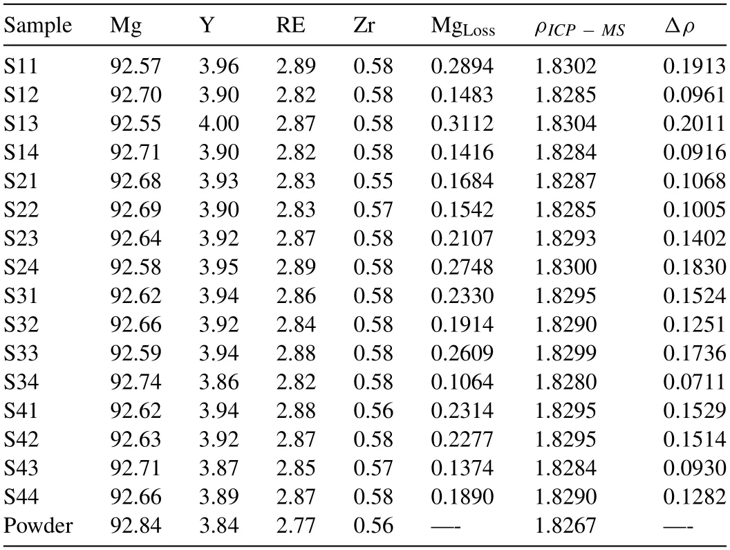
Table 4 Results of ICP-MS analysis of the chemical composition of major elements(wt.%) along with the calculated MgLoss (wt.%).The density of each sample(ρICP-MS;g/cm3) and the change in density of the sample (Δρ;%),with respect to the density of the powder,are also reported.
3.Results and discussion
3.1.Calculated MgLoss
The results of the ICP-MS elemental analysis of the samples and the used powder are presented in Table 4.Based on the ICP-MS data,the used powder in this study was Mg-3.84Y-2.77RE-0.56Zr,with a calculated density of 1.8267 g/cm3.The calculated MgLossin the 16 samples(Table 3) was 0.106-0.311 wt.%,with a mean of 0.205 wt.%.These values are well below those commonly reported experimentally obtained MgLossafter L-PBF processing of Mg and its alloys (≤4 wt.%) [18].This highlights the importance of keeping the level of energy input as low as possible to avoid intensive vaporization of Mg.Two consequences of Mg vaporization during the L-PBF process are noteworthy.First,vaporization changes the chemistry and density of the sample.The change in chemistry may influence the material microstructure.The calculated theoretical density of the samples,based on the reported element contents (ρICP-MS),and the density change (Δρ) of each sample with respect to the used powder density,are also given in Table 4.The calculatedΔρwas 0.0711% -0.2011%,an amount that is considerable in the context of calculating the relative density of each sample in the next section.Typically,the relative density of AM samples is measured with respect to the nominal density of the alloy.These relative densities are 99-100% when the LPBF process is optimized and the difference from 100% is a reflection of the presence of defects in the samples.Therefore,0.1-0.2% density changes amount to significant error in estimating the defect content of the samples and,as a result,in optimizing the L-PBF process.In the present study,these density measurements were used to calculate the relative densities of the samples.The second consequence of Mg evaporation within the melt-pool is to increase the recoil pressure,resulting in a more pronounced melt pool collapse and formation of keyhole defects.The outcome of this factor is quantitatively investigated in Section 4.3.

Table 5The optimal L-PBF process parameters for WE43 alloy.
The predictions of MgLossusing the model were compared to the ICP-MS measurements for validation of the model.The L-PBF process is simulated using this model,by moving the center of the melt pool using v and h parameters.Fig.4 shows the temperature (T) and Mg vaporization rate (JMg) at the center of the melt-pool and different depths,respectively,forP=160 W andv=900 m/s.Fig.4(a)shows that the temperature of a fixed point in the middle of the XY plane reaches a maximum of~2800 K when the laser scans the material,and,afterward,cools down to room temperature.The corresponding maximum temperature at the depths of 1-4 layers(that is,z=0.03-0.12 mm) is 2500 K-1600 K.Furthermore,the temperature at the center of the melt pool and top layer rises to 2200 K,1600 K,1200 K,and 1000 K when the laser scans the adjacent 2-5 tracks,respectively.The Mg evaporation rate at the solid-state,calculated using the Arrhenius relationship JMg=0.6exp(-25,000/RT) [36,37],is~105-106times smaller than that calculated using the Langmuir relation at the liquid state.Therefore,hereafter,five tracks of laser scans and five layers of melt pool formation and solidification were included in the calculations of MgLossconsidering the 813-913 K melting range for WE43 alloy.
Fig.5 depicts the variation of MgLosswith E at different combinations of E and h,as analyzed by ICP-MS and calculated using the present vaporization model.There is considerable scatter in the ICP-MS data,resulting in no clear trend for the variation of MgLosswith E and h.We suggest that the location dependence of the thermal history in the L-PBF process,the relatively small amount of MgLoss,and the typical contaminations and sampling error associated with ICP-MS analysis are among the contributing factors for the observed scatter.Thus,the empirical correction factorβ=0.4 in the Langmuir model (Eq.(1)) was determined by comparing the mean of the model predictions with the mean of the obtained ICP-MS data for all the samples.The inclusion of the empirical factorβaccounts for the fact that the Langmuir model estimates the net vaporization flux rather than accurately predicting it.More advanced models of vapor pressure that account for the degree to which the vaporized atoms condense into the solid-state [57,58] may yield more accurate predictions of MgLoss[38,39].Furthermore,the peak temperature in the melt-pool,calculated using the theoretical model,is higher than that expected because it does not account for the energy loss from the melt-pool due to vaporization.Nevertheless,usingβ=0.4 yielded an experimentally calibrated and relatively simple model that enables the study of the influence of L-PBF process parameters on MgLoss.
The present multiphysics model was used to investigate the influence of P,v,and t on calculated MgLossduring the L-PBF process (for all the simulationsh=0.09 mm) (Fig.6).At a given t,calculated MgLossincreases exponentially with an increase in P (Fig.6(a)) and at a given v,calculated MgLossincreases exponentially with an increase in P (Fig.6(b)).At a given v,there is a steep increase in calculated MgLosswith a decrease in t (Fig.6(c)),this being the result of increasing E.At a given P,calculated MgLossincreases markedly with the decrease in t and decrease in v (Fig.6(a,(b)),both of which result in higher energy densities during the process.

Fig.4.Temperature profile of a fixed point in the middle of the first laser track on XY plane over the time during the L-PBF process (a),and vaporization rate of Mg at the same point over time (b).
3.2.Densification
The variation of relative density of the manufactured samples,as determined using the Archimedes method and calculated using optical microscopy image analysis,with E is shown in Fig.7.Based on the study presented in the Appendix,the considered 16 samples were carefully selected to have a manufactured product that has high densification,with E ranging from 43.1 to 74.1 J/mm3.Thus,each of the samples had>98% relative density and the change in the measured relative densities with the change in the used energy density is within 2%.Three key trends in these results are highlighted.The first is that the variation ofρRel.(Arch.) with E follows a quadratic pattern,withρRel.(Arch.) increasing up to E to~60 mJ/mm3followed by decreasing with further increase of E.This trend is the same as that reported in literature studies for L-PBF of most alloys,including WE43 [20].The quadratic behavior is attributed to the competition between the amount of LF and KH defects in the samples.Increasing E decreases the amount of LF defects while increasing the amount of KH defects.Nevertheless,samples S42 (v=1125 mm/s andh=0.09 mm)and S31(v=1050 mm/s andh=0.08 mm)exhibited the highest measuredρRel.(Arch.) while the quadratic fit suggests that samples S32(v=1050 mm/s andh=0.09 mm)and S41 (v=1125 mm/s andh=0.08 mm) have the highestρRel.(Arch.).Each of these four samples hasρRel.(Arch.)>99.3-99.6% and the differences between their individualρRel.(Arch.) values are within the standard deviation of the collection of results.
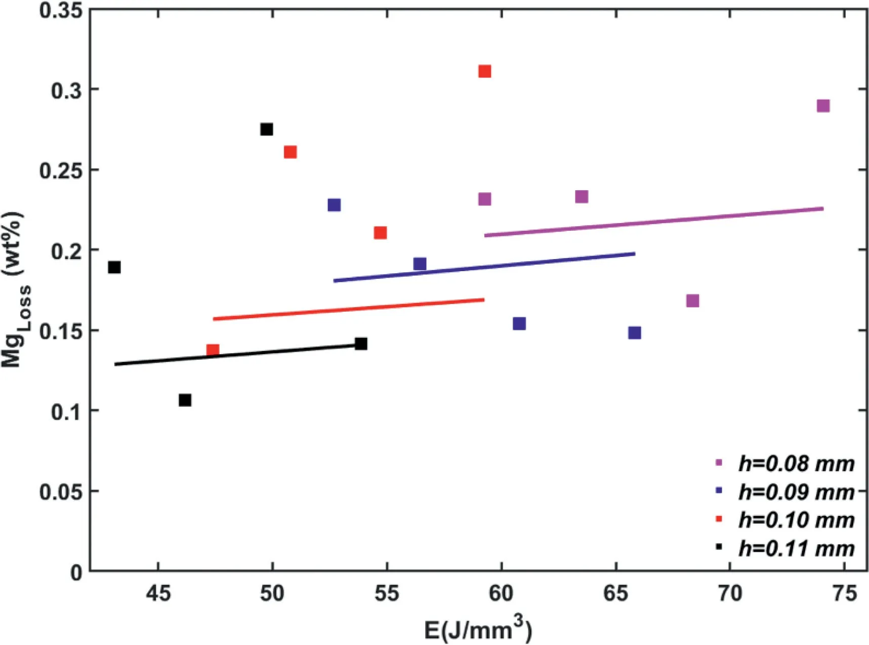
Fig.5.Variation of MgLoss with volumetric energy density (E) and hatch spacing (h),as analyzed using MgLoss obtained using ICP-MS (squares) and MgLoss calculated using the present vaporization model with β=0.4 (solid lines).
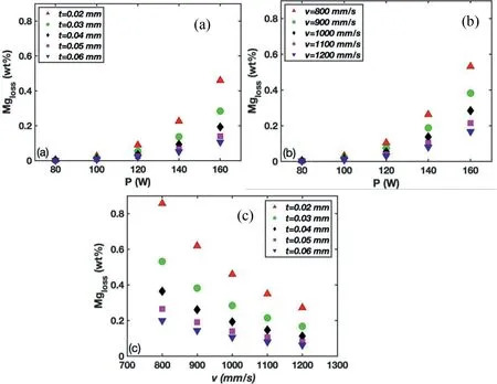
Fig.6.Variation of MgLoss with laser power (P) and layer thickness (t) (a),P and scanning speed (v) (b),and v and t (c).

Fig.7.Variation of the relative density with volumetric energy density (E) for all the samples considered in this study.The sample codes (Table 3) are also listed in the figure.The black solid line is a quadratic fit to the ρRel.(Arch.) results.
The second key trend is that the calculatedρRel.(Img.) for all the samples is smaller than theirρRel.(Arch.) counterparts;these two density measurements are approximately equal only for the S44 sample.A closer look at the method used to calculateρRel.(Img.) explains this behavior.ρRel.(Img.) is calculated using the percent of area defects on the horizontal and vertical surfaces with respect to the build plate (the blue upward and downward triangles in Fig.7,respectively).LowerρRel.(Img.) thanρRel.(Arch.) indicates that the defects have a preferred orientation in the horizontal and vertical directions;that is,the larger areas of the three-dimensional (3D) defects are oriented in the horizontal and vertical directions.Thus,extrapolating the area defect content to the volume defect content results in a higher 3D defect calculation than the actual content,leading to the lower calculated density using this method.Furthermore,a small difference betweenρRel.(Arch.)andρRel.(Img.) for a sample implies more spherical and/or homogeneously oriented defects for that sample.The samples manufactured using a low energy density (samples S44(v=1125 mm/s andh=0.11 mm) and S33 (v=1050 mm/s andh=0.1 mm)) are the best performing samples from this point of view,with the relative densities of 98.8-99.2%.It is worth noting that the reportedρRel.(Arch.) of this study is based on the actual density of the samples considering the MgLoss.Thus,the present findings do not support the explanation given in literature studies for this difference as being due to MgLossduring the L-PBF process [13,14,19,20].
The third key trend is thatρRel.(Img.) from horizontal surfaces are higher than their counterparts measured from the vertical surfaces except for S44,S43,and S23,which are the samples manufactured using the lower end of the range of energy densities used.Since,the KH/LF defects increases/decreases by increasing E,these findings suggest that KH/LF defects tend to orient in the vertical/horizontal directions.S43 (v=1125 mm/s andh=0.1 mm) and S32 (v=1050 mm/s andh=0.09 mm) have equal defect content measured from the horizontal and vertical surfaces while S44 and S33 show relatively small differences between the two mentioned defect contents.
3.3.Defect classification
Fig.8 shows three images of samples manufactured with the highest (S11),lowest (S44),and mean (S31) values of E to illustrate the types of the observed defects in the samples and change in characteristics of the defects with change in E.We focused on four types of defects: lack of fusion (LF),gas porosity,spatter/oxide contamination,and keyhole (KH).It should be noted again that the energy densities for all the considered samples are chosen based on the results detailed in the Appendix such that a small amount of LF defects were expected.A high number of both large and small pores are seen in Fig.8(a) for the S11 sample followed by Fig.8(b)for S44.In contrast,S31 shows a substantially lower number of defects with smaller areas.As indicated by the arrows on Fig.8,larger pores appear to be mostly KH pores characterized by their near-circular shapes as opposed to LF defects,which are also large pores but with irregular shapes.The dimensionless power or P∗used in the present study (121) was higher than those used in studies reported in the literature(48-101 [35-39]).High P∗results in a higher incidence of KH defects compared to LF defects in samples.
There were very few melt spatters or trapped oxides (evidenced by few spots in Fig.8).At high E,the powder bed starts to melt violently,and this results in excessive vaporization and spattering.The incidence of spatters can be decreased by operating at a lower value of E,which will also result in decreasing the number of KH defects.However,due to the high affinity of Mg for oxidation,the high melting point of the oxide layer around the powder,and the low laser light absorbance,high values of E are required to avoid LF pores[8].As a result,a larger amount of KH defects is to be expected in the L-PBF of Mg and its alloys compared to the case for other metallic materials.
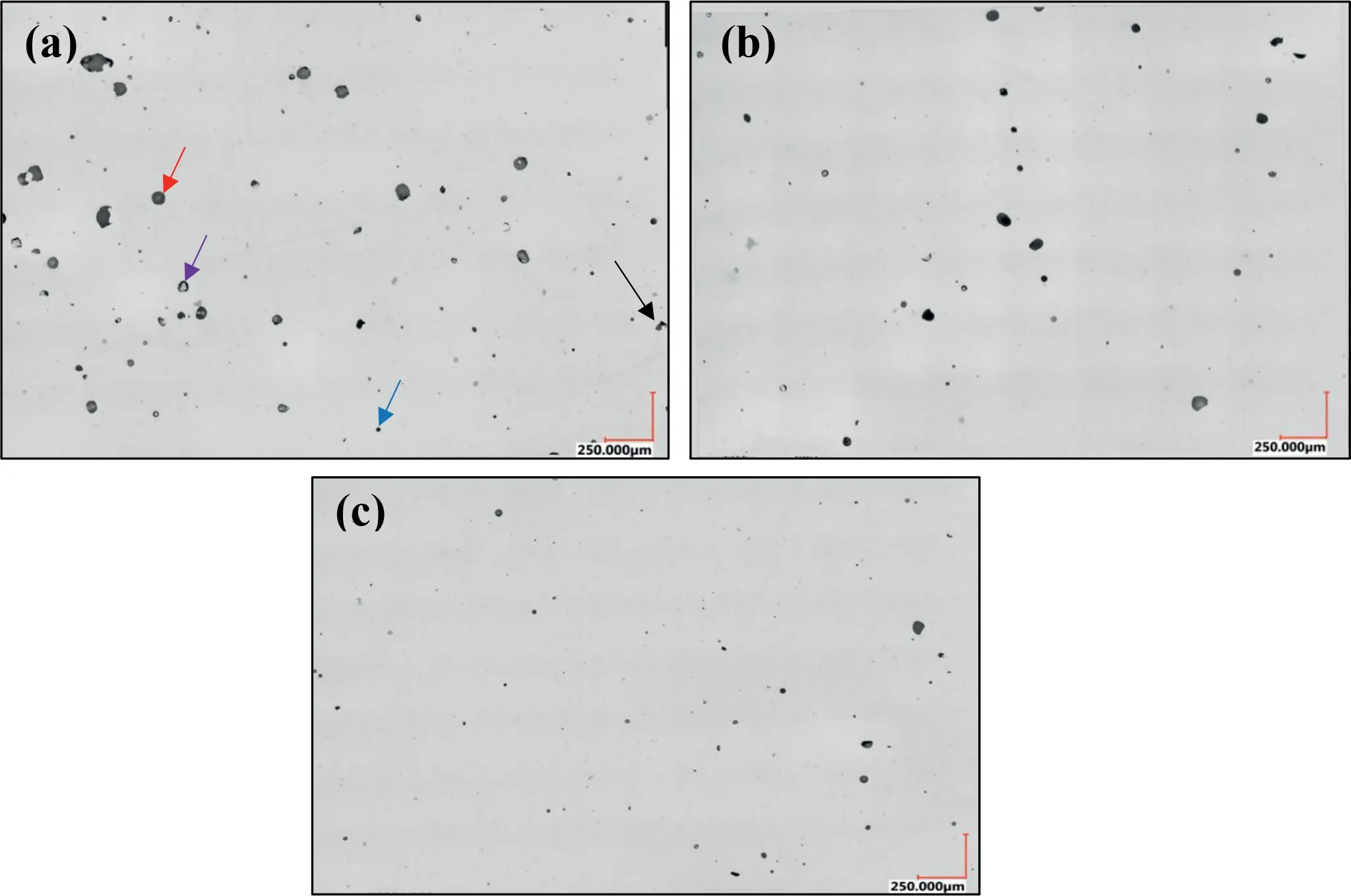
Fig.8.Optical images of sample S11 (a),sample S44 (b),and sample S31 (c) corresponding to the highest,lowest,and mean input energy densities,respectively.Black,red,blue,and purple arrows point to examples of LF,KH,spatter/oxide contamination,and gas porosity.

Fig.9.Variation of with ψ for all the defects observed in all the 16 samples of this study (a) and variation of the classifeid KH and LF defects in the defect population (pore amount) with energy density (E) for each sample (b).
The smaller pores in Fig.8 are most likely gas pores.It is also possible for some of the smaller pores to be the smaller cross-sections of LF or KH pores;therefore,the smaller pores were excluded from the quantitative defect classification.The gas pores may originate from the entrapment of inert gas circulating over the powder bed or pre-existing gas pores inside the powder particles.Pre-existing gas pores have been identified as the cause of gas pores in fiber laser welds of AM60,AE42,and AS41 cast Mg alloys [40].Evaporation of Mg may exaggerate the entrapment of gas during rapid solidification,leading to a substantially higher number of gas pores in L-PBF Mg alloys compared to other alloys,such as Ti-6Al-4V.Hydrogen porosity may be considered as another source for the high number of gas pores in the samples.Hydrogen is the only gas that can readily dissolve in molten Mg alloys.It is suggested that the ejection of dissolved hydro-gen from the solid during solidification results in the formation of small spherical pores.This suggestion is based on the report of ejection of hydrogen from the Mg17Al12intermetallic compound in AZ91 alloy,which strengthens the nucleation and/or growth of micro-porosity during the last stages of solidification [41].However,in the present study,the formation of ZrH2and the narrower freezing range in WE43,due to the presence of,respectively,Zr and REs [61],result in the reduction of the number of hydrogen porosity.Nevertheless,in all the samples in the present study,there are large numbers of micron and sub-micron pores,which are as categorized as gas porosity,regardless of the L-PBF process parameters used.
Although small numbers of LF and KH defects are observed in the 16 samples analyzed,it appears that the mean defect size and the nature of these defects change among these samples.To better understand these differences,at each E,a small number of defects were classified using their characteristic length (defined as the square root of the defect area ()) and roundness (ψ).Note thatwhere Dmaxdenotes the maximum diameter of a defect.ψranges from 0 to 1,whereψclose to 0 indicates that the defects are elongated in one direction andψclose to 1 means the defect is approximately circular.Fig.9(a) shows the distribution of all the defects for all the 16 samples of this study on themap.Here,it is assumed that any defect with>20 μm andψ >0.65 represents a KH defect and any defect with>20 μm andψ <0.35 represents an LF defect while the rest of the pores are unclassified.The LF(blue) and KH (red) regions corresponding to this definition are also shown in Fig.9(a).As expected,in each sample,there is a larger number of KH defects than LF defects.This is because the results of the preliminary study (see Appendix)guided the selection of the L-PBF process parameters used in this study,resulting in samples that had relatively high densification and few LF defects.While the proportion of KH defects in the defect population (pore amount) increases with an increase in E,the influence of E on the pore amount of LF defects is negligible (Fig.9(b)).These findings are reasonable given the narrow range of E used in the study(see Appendix).Additionally,the best fit to the results of the variations of pore amount of KH defects with E is a power equation,a trend that is the same as reported by Snell et al.for 2D image analysis of pores in L-PBF Inconel 718 alloy samples [42].
Further analysis of the difference between average defect size and roundness measured for the normal and paralled cross-sections,provides interesting information regarding the anisotropy of the defects for samples such as the three representative micrographs shown in Fig.8;the micrographs for these samples are provided in Fig.B.1.Average roundness(ψ) and average defect area for normal cross-section of S11 were 0.66 and 64 μm2,respectively.In contrast,the same two quantities for the parallel cross-section of the same sample were 0.59 and 124.5 μm2which are both less than those of the normal cross-section.For S44,average roundness and average defect area were 0.62 and 85 μm2for the normal cross-section,whereas those of the parallel cross-section were 0.59 and 28 μm2,respectively.As mentioned before,this can be understood from Fig.7 and the fact that S44 along with S43 and S23 were the only three exceptions regarding the difference between the average defect areas of normal and parallel cross-sections;i.e.,For all the other samples,the upward triangles are well below the downward triangles.
3.4.Optimal L-PBF process parameters
The optimal L-PBF process parameters,based on the calculated MgLoss,densification,and defect characteristics,are listed in Table 5.For comparison,optimal L-PBF processing parameters reported in the literature for this alloy are also presented in Table 5.Note that dimensionless process parameters in the cited studies are calculated based on the information reported in those studies.The optimal dimensionless volumetric energy density or E0∗in the present study is comparable to those reported by Gangireddy et al.[17] and Hyer et al.[20] but much lower than those reported by Bar et al.[16],Zumdick et al.[18],and Esmaily et al.[19].Considering the normalized processing diagrams suggested by Thomas et al.(See Fig.2 in ref.[6]),for Ti-6Al-4V,316 L stainless steel,Inconel 625,Inconel 718,CM247,and FeCoCrNi high entropy alloy samples manufactured using AM,optimum E0∗should be<16.Considering the presented results,t this rule should also apply to WE43 manufactured using L-PBF.With the present optimal L-PBF process parameters,the mean calculated MgLossfor the 16 samples was 0.205 wt.%.By comparison,MgLossof 2 wt.% was reported by Zumdick et al.[18] corresponding to E0∗of 50.36.From the present results and those reported by Gangireddy et al.[36] and Hyer et al.[39],it thus appears that low E0∗is needed to minimize MgLossand,simultaneously,maximize densification.
4.Conclusion
The study investigated three aspects of WE43 alloy samples/parts manufactured using L-PBF,these being Mg loss due to vaporization (MgLoss),densification of the manufactured samples,and detailed characterization of the defects in those samples.For the first aspect,a multiphysics model was developed and used to calculate the temperature profile and,hence,MgLoss,as a function of four key process variables(laser power (P),laser scanning speed (v),layer thickness (t),and hatch spacing (h)).Mean calculated MgLosswas 0.205 wt.%,which was within the range of experimentally determined loss also measured in this study.At a given t,calculated MgLossincreased exponentially with an increase in P.For the second aspect,densification of 16 samples manufactured using optimal values of P,v,t,and h (as determined in a preliminary study that is summarized in the Appendix in the present report) was obtained using a modification of Archimedes method (relative density (ρRel.(Arch.)),with the mean value being 99.2%.Optical microscopy image analysis of the same 16 samples characterized~0.1 -~0.3% and 1-~2% of the defects in them as lack of fusion and keyhole(KH) defects,respectively.The proportion of KH defects in the defect population (pore amount) of the samples increased exponentially with an increase in E.When the whole collection of results obtained in the study were considered,four sets of optimal values of the process variables for L-PBF processing of WE43 alloy are suggested.
Acknowledgments
The authors thank the Tennessee Institute of Regenerative Medicine (TennIRM) for funding the study.The authors also thank Professor Gladius Lewis for reading the manuscript and providing valuable comments/edits.
Appendix A: Preliminary Densifciation Study
A.1.Methods
Here,the two Taguchi DoEs are presented that resulted in the selection of laser powerP=160 W,layer thicknesst=0.030 mm,laser scanning speedv=900-1125 mm/s,and hatch spacingh=0.08-0.11 mm.The signal-to-noise (S/N)ratio is a measure of how the response variable(s) change relative to a nominal or target value under different noise conditions.Depending on the purpose of the experiment,a suitable type of S/N ratio can be selected and used for process optimization.Since the purpose of the present study was to maximize the density or minimize the porosity,the larger-thebetter type of S/N ratio is used for analyzing the densification.This type of S/N ratio for each level combination is calculated

where Y denotes response for the given factor level combination and n stands for the number of responses in the factor level combination.A commercially available software package(Minitab 20.1.2)was used to create the two static Taguchi designs with 3 factors,each having 5 levels,and one response for two fixed layer thicknesses (t) of 0.02 and 0.03 mm.This resulted in two designs,each having 25 parameter sets.Table A-1 lists the parameter levels and their actual values together with the equivalent E values for the given factor level combination.
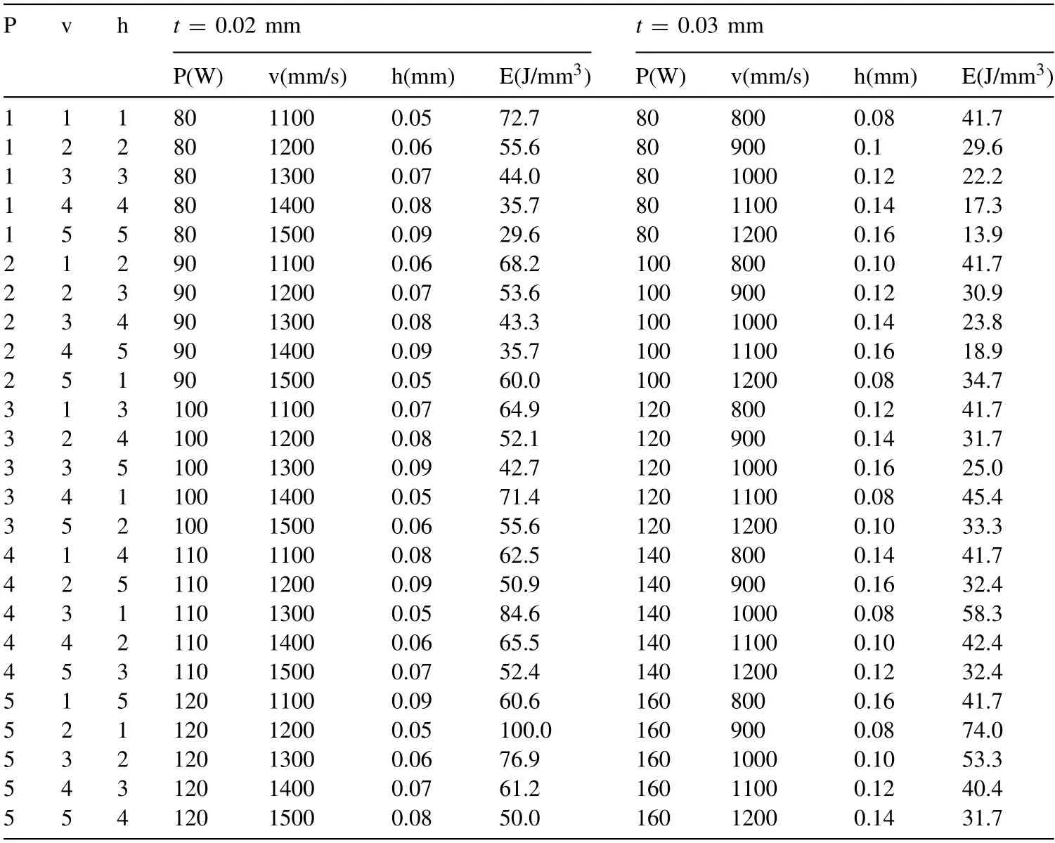
Table A-1The L-PBF process parameter levels and the corresponding values for the two Taguchi DoEs used in the preliminary study.
A.2.Results and Discussion
The density measurements were performed as explained in Section 2.2 and the relative densities (ρrel.(Arch.)) were plotted against the energy density (E).Fig.A-1 shows the variation of (Arch.)of manufactured samples with E when t was 0.02 mm or 0.03 mm.Higher densifications (>95%) were only achieved at medium to high range values of the input energy (E >40 J/mm3).Considering the data fort=0.02 mm,the most important observations were that theρrel.(Arch.)of several samples produced at high energy inputs had densification slightly>100% and these parts showed substantial variations in the repetitions of the measured density for the same set of process parameters.This can only be justified if the material essentially changes due to Mg vaporization during L-PBF and becomes heavier.This issue is discussed in sub-section 3.1.Furthermore,visual inspection of the samples showed that at small values of h,the top surface was rough,suggesting that there was over-melting and boiling in those parts.In contrast,ρrel.(Arch.) of the parts manufactured witht=0.03 mm was ≤100%.Consequently,for the studies reported in Section 2.2,we focused on the samples produced usingt=0.03 mm.
The main effects plots of the two Taguchi DoEs are presented in Fig.A-2.To maximize the density,S/N ratios must be maximized and standard deviation minimized.Using the Delta values (the range of the S/N ratio),P-v-h factors were assigned ranks 1,2,and 3,respectively.Considering Fig.A-2(a) fort=0.02 mm,it was difficult to identify a control factor setting that minimized the variability caused by the noise factors.This was because of the low sensitivity of the design to the values of P,v,and h (note the difference in the ranges of the S/N ratios in Fig.A-2).Nevertheless,P has the largest effect on the S/N ratios and is ranked 1.The plots have large slopes and,therefore,there are main effects.However,the difference in the vertical position of the plotted points becomes smaller at high levels of the P factor and low levels of h and v factors.This means that the magnitude ofthe main effect becomes smaller at these factor levels.Simply put,there is only a very small difference between 110 and 120 W for P,1100-1200 mm/s for v,and 0.05-0.07 mm for h.Although these plots indicate that a control factor setting with high power,low velocity,and small hatch spacing should yield a favorable result,visual inspection of the asbuilt samples showed that their top surface was rough,with over-melting being noticeable on samples manufactured using small values of h.

Fig.A-1.The plot of the relative densities of the parts produced with the two different layer thicknesses for the two Taguchi DoEs.
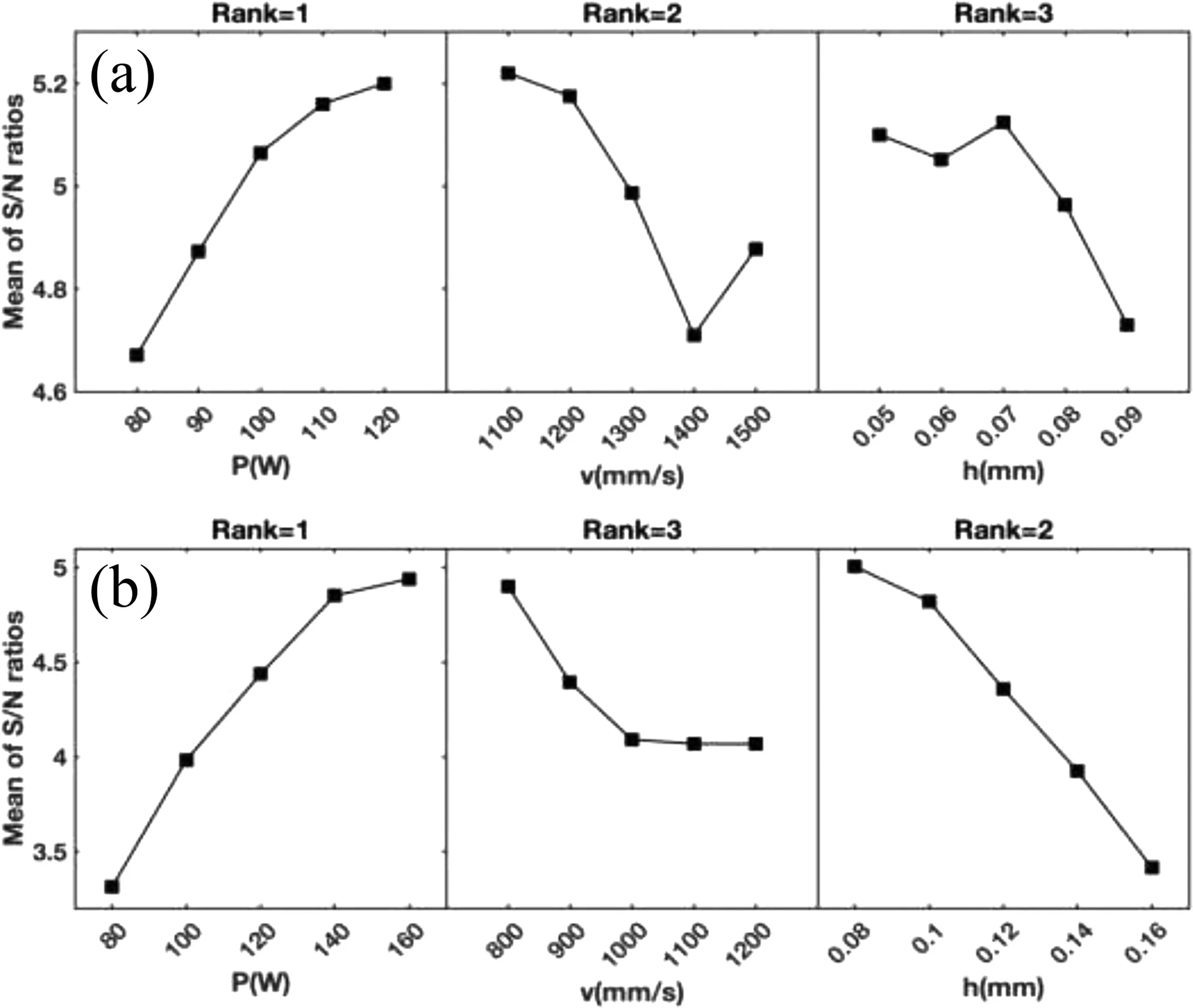
Fig.A-2.Main effects plot for the S/N ratios of the parts manufactured using t=0.02 mm (a) and t=0.03 mm (b).
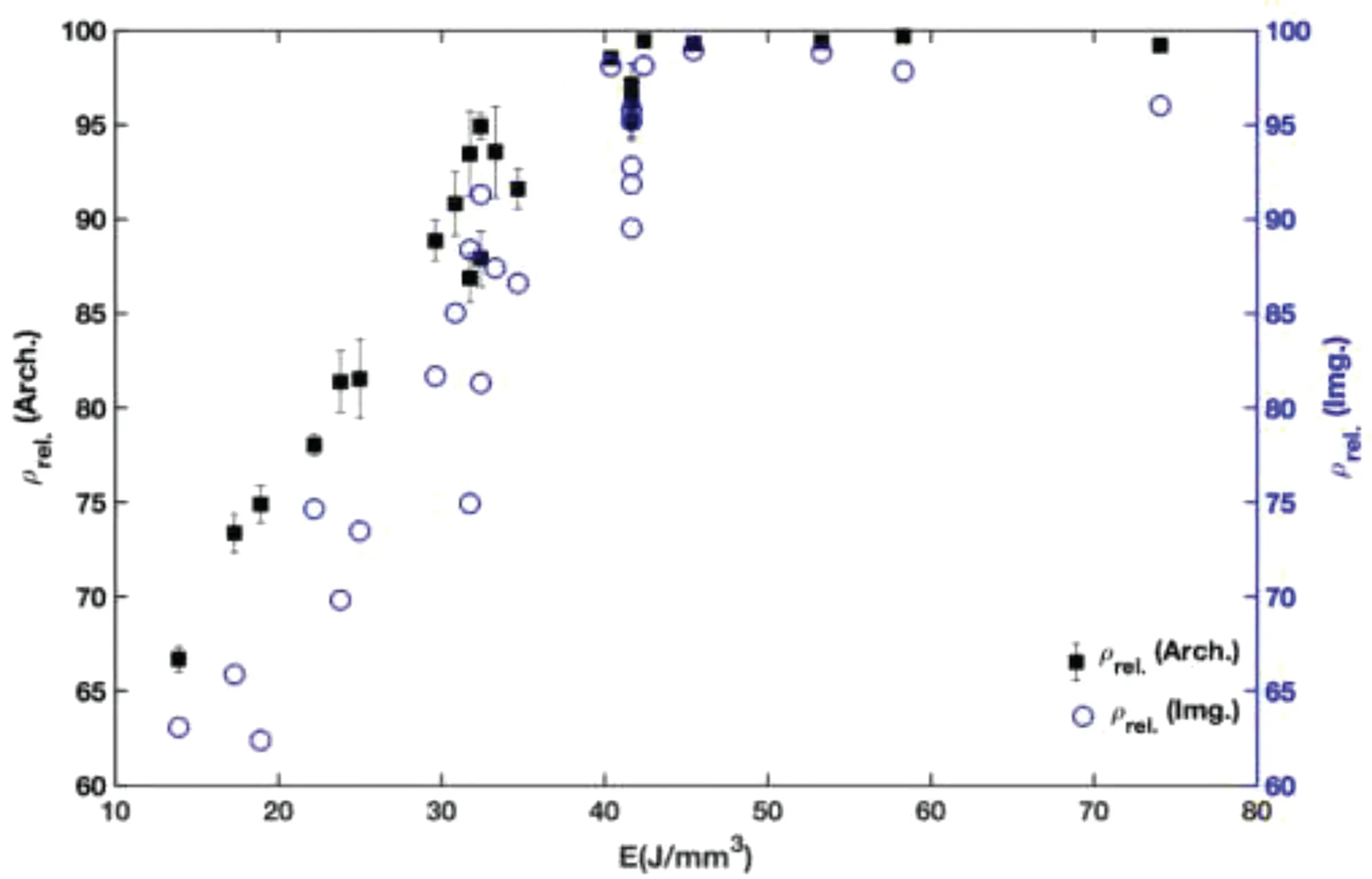
Fig.A-3.Comparison of the relative densities obtained by image analysis and Archimedes method for the parts produced with t=0.03 mm.
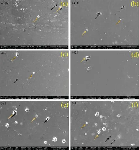
Fig.A-4.SEM micrographs taken from normal (N) and parallel (P) to the build direction cross-sections of three selected samples: 431 (a,b),442 (c,d),and 521 (e,f) (Black arrows either indicate large pores caused by the collapse of keyholes or small pores due to gas/boiling porosity and yellow arrows indicate oxides or SiO2 particles trapped in pores after polishing of the sample.
On the other hand,for parts manufactured witht=0.03 mm,511 is a favorable control factor setting that minimizes the resultant variability of the noise factors.Using the Delta values,P-v-h factors were assigned ranks 1,3,and 2,respectively.Compared with parts produced witht=0.02 mm,it was found that P still has the largest effect on the S/N ratios and the means.Except for levels 1000-1200 of v factor,plots have large slopes and,therefore,there are main effects.The difference in the vertical position of the plotted points becomes smaller at high levels of P factor and low levels of h factor,while it becomes larger at low levels of v factor.It appears that the response is insensitive to levels 1000-1200 of v factor.Again,these plots indicate that a control factor setting with high power,low velocity,and small hatch spacing should yield a favorable result.Unlike the previous design,however,there was no visible sign of over-melting on the top surfaces of the manufactured samples.Comparison of these two designs reveals another important finding,which is that the design witht=0.03 mm has a higher range (on the vertical axis),and there is no change in the slope sign anywhere on the main effects plots.The limited range also means that it is harder to stay in a favorable input energy range without resorting to unusually high scanning velocities and/or low hatch spacings.
To further analyze the densification of parts produced att=0.03 mm,ρrel.(Arch.)andρrel.(Img.) of these parts were compared (Fig.A-3).Bothρrel.(Arch.)andρrel.(Img.) show a plateau at high E values (E >40 J/mm3).On the other hand,at low E,there is considerable scatter in theρrel.(Img.)data.This can be explained by the nature of defects found in the parts manufactured using low or insufficient input energies.For these parts,LF with large irregular shapes can cause considerable variation in image analysis of defects.On the other hand,gas or KH pores tend to be spherical,with a lower effect on the accuracy of data at forming or over melting zones.As such,the image analysis results are more reliable at medium to high input energy range,where there are fewer LF defects.
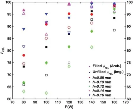
Fig.A-5.Variation of relative density with laser power (P) and hatch spacing (h).
By considering maximum achievable density based on the Archimedes principle,three samples were selected (431,442,521) and their SEM micrographs are presented in Fig.A-4.Micrographs were taken at 100X magnification and in both normal (N) and parallel (P) cross-sections to the build direction.There is no sign of irregular or LF defects.This is further confirmation that samples manufactured usingP=140 or 160 W lie within the formation zone.Round gas porosity or those KH defects induced by over melting or melt pool instability were still present in these parts withρrel.(Arch.)values>99%,albeit with slightly varying degrees.On the other hand,white regions seem to be oxide particles,intermetallic,or other types of inclusions.Although the sample manufactured usingP=160 W seems to contain more of such small defects,density measurements and image analysis results showed that withP=160 W there was less variation in the density of samples and this level of laser power is,therefore,more promising for achieving better densification.To examine this issue more closely,consider the variation ofρrel.(Arch.)andρrel.(Img.) with P (Fig.A-5).P=160 W has led to the formation of samples that present close to 90% and above densification,and at the same time,the overall change in density at different levels ofhremains in the narrowest range when compared to the rest of the utilized laser power levels.For the same reason,more attention is being paid to the development of a manufacturability-based design withP=160 W in this study.Furthermore,a higher power is preferred because of the high melting point of MgO and poor laser light absorbance of Mg [8].
Appendix B
Representative Micrographs of L-PBF Samples

Fig.B.1.An example comparision between the normal (N) and parallel (P) cross-sections of samples S11,S31,and S44.
杂志排行
Journal of Magnesium and Alloys的其它文章
- Improving the Young’s modulus of Mg via alloying and compositing -A short review
- Surface modifciation of magnesium alloys using thermal and solid-state cold spray processes: Challenges and latest progresses
- Preparation,structure and properties of Mg/Al laminated metal composites fabricated by roll-bonding,a review
- A review on recent advancements in biodegradable Mg-Ca alloys
- Pore structure of porous Mg-1Mn-xZn alloy fabricated by metal-gas eutectic unidirectional solidification✩
- Role of bimodal-grained structure with random texture on mechanical and corrosion properties of a Mg-Zn-Nd alloy
