Reliability Analysis of Repairable System with Multiple Closed-Loop Feedbacks Based on GO Method
2022-08-28HuinaMuYuhangCuiXinrongHouXiaojianYiWentaoMaWeiLiu
Huina Mu, Yuhang Cui, Xinrong Hou, Xiaojian Yi, Wentao Ma, Wei Liu
Abstract: In order to solve the problem of reliability modeling and the analysis of complex systems with multiple closed-loop feedbacks, a new reliability analysis method for repairable systems with multiple closed-loop feedbacks is proposed based on the goal-oriented (GO) methodology. Firstly,the basic theories and advantages of GO method are introduced. Secondly, a type-24B multiple closed-loop feedback structure operator is proposed through GO method with its operation formula given, which expands the types of GO method operators and the application scope of their reliability analysis. Finally, taking a certain type of diesel engine fuel supply system an example, the quantitative and qualitative analysis is carried out through GO method, Monte Carlo simulation as well as FTA respectively. The availability results verify the availability of the proposed type-24B operator in the reliability analysis of multiple closed-loop feedback systems. The qualitative analysis results indicate the accuracy and usability of the GO method as a qualitative analysis method.
Keywords: multiple closed-loop feedback; goal-oriented (GO) method; operator; reliability analysis
1 Introduction
The goal-oriented (GO) methodology [1] is a success-oriented system reliability analysis method,in which the GO algorithm is used and the GO operation is performed according to the GO model to obtain the reliability analysis results of a system. The GO method analysis is mainly to establish the GO model and perform GO operation. The GO model can be directly converted from the system flow chart, schematic diagram or engineering structure diagram. The GO operation is to compute the state probability of the signal flow attributes from the input operator according to its operation rules after determining the GO model and the operator state probability data. The two major elements of the GO model and GO operation are signal flow and operator.
The GO method was originally applied to the reliability research of weapon systems by the American military, which was gradually applied to the fields including transportation, water supply systems, nuclear industry systems and power systems [2, 3]. Yi Xiaojian proposed a reliability analysis method for multi-failure-mode repairable system GO method [4], and considered the redundancy structure maintenance correlation as well as the system multi-failure-mode unit using the GO method to complete vehicle-integrated transmission. The reliability of a hydraulic oil supply system was analyzed [5, 6]. Shen Zupei et al. proposed a common signal correction algorithm and a common signal accurate algorithm for GO method respectively. The reliability analysis results of GO method of many engineering systems prove that the results obtained through the accurate algorithm of common signals are closer to the engineering practice [1]. On the basis of 17 standard operators, Shen Zupei proposed a type-18 operator to describe an alternate structure composed of a single input device. Yi Xiaojian proposed a combination of type-18A and type-20 operators to describe an alternate structure composed of multiple input devices [7], and defined a type-19 operator to describe the components stabilizing the performance value of the system [8].Some new operators were created to solve more engineering problems, a combination of type-15B and type-22 operators was completed to describe multifunctional elements in multifunctional complex systems [9], a type-21 operator was obtained to describe the input signal units of multi-mode multifunctional modes, type-23 logical operators were used to describe the logical relationship of the output of multi-function-mode systems, type-25 operators were used to describe the transformation of scalar and vector signal flow [8], and type-24 operators were used to describe a multiinput closed-loop feedback link, thus, breaking the GO method that has long been a limitation of the inability of model closed-loop systems [10,11]. Compared with commonly used reliability analysis methods such as FTA and FMEA, the GO method is more suitable for reliability research on time-series and multi-state systems,as its reliability analysis process is simple and easy to understand, and its GO model is more closely integrated with the system, which is convenient for different engineering and technical personnel to operate.
Reliability research on the GO method for complex repairable systems with closed-loop feedbacks as well as multi-function and multiple-failure modes is an important direction of theoretical research on the GO method. Since a type-24 operator can only be used to describe a single closed-loop feedback link, it is impossible to model a system with multiple closed-loop feedback links. Therefore, a type-24B multiple closedloop feedback link operator is proposed in this paper, which further improves theories of the GO method and makes it applicable to the reliability analysis of systems with more complex structures.
2 Reliability Analysis of Multiple-Closed-Loop Feedback Systems
2.1 Operators with Multiple-Closed-Loop Feedback Links
Multiple-closed-loop feedbacks widely exist in complex systems. A closed-loop feedback link usually consists of multiple input signals, output paths and multiple feedback paths. The structure of an output path or a feedback path is not restricted, and the input signals can either be independent input signals or act on the output path and feedback path units, and its structure diagram is shown in Fig. 1. Since the existing operators cannot be used to describe the abovementioned multiple-closed-loop feedback links, it is impossible to model the GO graph of a system containing such links. Therefore, a type-24B functional operator is defined in this paper to describe multiple-closed-loop feedback links, and the corresponding GO operation formula is derived.
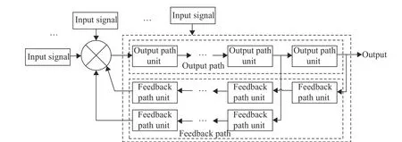
Fig. 1 Schematic diagram of a multi-feedback closed-loop structure
2.1.1 Define Type-24B Operators The symbol of a type-24B operator is shown in Fig. 2, which is defined as follows: the output and feedback paths are equivalent to moduleCand moduleFj,j=1,2,··· ,m.SiandRrespectively represent the input and output signals of the type-24B operator,i=1,2,··· ,n. The reliability parameters of moduleCand moduleFjare those of the type-24B operator;C,Fj,SiandRhave 2 states: state 1 is the normal state, and state 2 is the fault state.

Fig. 2 Symbol of a type-24B operator
2.1.2 GO Formula of Type-24B Operators
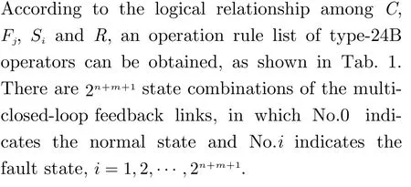

Tab. 1 List of state combinations of a type-24B operator
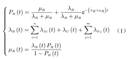
According to Tab. 1 and Markov’s theory,the quantitative operation formula of type-24B operators is as follows

2.2 Reliability Analysis Method of Systems with Multiple-Closed-Loop Feedbacks Based on GO Method
The general reliability analysis process of a system with multiple closed-loop feedbacks based on GO method is: system analysis, establishment of GO model, GO operation and system evaluation.
2.2.1 System Analysis
1)Analyze system structure, engineering principles and functionality. Determine the interface and logical relationship as well as the input and output boundary conditions of the system.
2)Determine system characteristics: determine whether the system has closed-loop feedback links, and analyze the input signals, output paths as well as feedback paths of the closed-loop feedback structure. Determine whether the system has multiple-input or multiple-output logic, and analyze the logical relationship between its input and output.
3)Determine the success criterion as the criterion for the successful operation of the system.
2.2.2 Build GO Model
1)Determine the operator type of the unit and its logical relationship with the system according to system analysis.
2)Establish the first-level and higher-level GO model of the system according to the schematic diagram of its structure.
2.2.3 GO Operation
1)Data processing of system units and structures is performed to determine their GO operation data.
2)Quantitative analysis through GO method. According to the GO model and the GO operation rules, select an appropriate algorithm to perform the GO operation, so as to obtain the state probability of the system output.
3)Qualitative analysis through GO method.According to the GO model and the GO operation rules, the GO operation is carried out to obtain the minimum cut sets of the system in each order.
2.2.4 System Evaluation
The quantitative and qualitative analysis results through the system GO method can provide a basis for system reliability evaluation, design improvement and fault diagnosis.
The specific reliability analysis process of the system with multiple closed-loop feedbacks based on the GO method is shown in Fig. 3.

Fig. 3 Flow chart of reliability analysis of a system with multiple closed-loop feedbacks based on GO method
3 Example Application
In order to check the superiority, feasibility and rationality of the method proposed in this paper,the fuel supply system of a heavy vehicle diesel engine is taken as an example in this paper, and under the premise of the same working principles,the structure of the fuel supply system is finetuned and integrated as an example structure. In order to facilitate the system reliability analysis and compare with existing methods, the following assumptions are made.
1) Assume that the probability of successful input of the power switch operation signal, foot pedal operation signal, fuel signal and air signal is 0.999 998, the probability of successful input of fuel pump drive signal, fuel injection pump drive signal and camshaft drive signal is 0.999 980, and the availability of some pipes as well as interfaces in the system is 1.
2) Ignore the downtime correlation among components.
3) Assume that the equipment is only repaired at the basic level, the maintenance is mainly a replacement repair, and the repair time is normally not more than 2 h [12].
3.1 Analysis of a Diesel Fuel Supply System(DFSS)
A DFSS is mainly composed of two parts: oil supply and air supply. The specific components are shown in Fig. 4. Its working principle is that after the fuel in the fuel tank is filtered by the coarse filter, the fuel pump overcomes the flow resistance in the fuel filter and the pipeline with a certain delivery pressure under the action of its driving signals, and the fuel is delivered to the fuel injection pump, which increases the fuel to a certain pressure driven by itself, the high-pressure fuel is injected into the cylinder through the fuel injector according to specified time and injection rules, then the return fuel from the fuel injection pump returns to the fuel delivery pump through the fuel cooler, and the return oil of the injector flows into the expansion tank through the float valve. The electronic control system controls the opening and close of the oil circuit and the adjustment of oil volume through the oil cutoff solenoid valve and the speed governor. The clean air filtered by the air filter is sucked into the compressor and enters the intake manifold.Meanwhile, the overhead intake camshaft acts on the intake valve assembly, so the intake valve is opened, and the air enters the cylinder, where it is compressed, with the temperature and pressure rising sharply. During the power stroke of the diesel engine, the fuel atomized by the injector is injected into the cylinder, forming a combustible mixture with the compressed gas, which ignites and burns violently, releasing a lot of heat, and the high-temperature as well as highpressure gas generated through the reaction is expanded to push the piston to move. Under the action of the exhaust camshaft, the exhaust valve is opened, and the exhaust gas is discharged from the cylinder to drive the turbine to perform in a certain direction, so that the coaxially connected turbine and the compressor rotate at a high speed, and the exhaust gas is discharged into the atmosphere after the work. Through analysis, it can be known that the input signals of the system are power supply, power switch operation signals, pedal operation signals, fuel, fuel pump drive signals, fuel injection pump drive signals,air and camshaft drive signals, and the output signal of the system is exhaust gas.
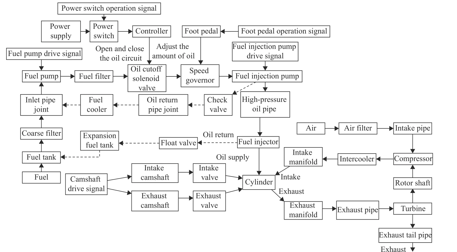
Fig. 4 Functional block diagram of the fuel supply system
According to the above analysis, the fuel supply part of the DFSS is a five-input doubleclosed-loop feedback structure, and the gas supply part is a four-input single-closed-loop feedback structure; the fuel and air form a combustible mixture in the cylinder and the exhaust gas is in a four-input one-output control logic after combustion. The success criterion of the DFSS is capable of properly supplying the cylinders with fuel and air to form a combustible mixture and discharging the exhaust gas into the atmosphere.
3.2 Establish GO Model
Operators are selected according to an analysis of the DFSS, and the reliability parameters corresponding to each component can be obtained according to the relevant engineering manuals or engineering test data statistics, as is shown in Tab. 2.According to the analysis of the DFSS, a twolevel GO model is established for the DFSS [8].The first-level GO model (the GO model with five-input double-closed-loop feedback links, and that with four-input single-closed-loop feedback links) and the second-level GO model (system GO model) of the DFSS are shown in Fig. 5, Fig. 6 and Fig. 7 respectively. The first character of the operators in Fig. 5, Fig. 6 and Fig. 7 represents their type, the second character represents the operator number, and the character on the signal flow represents the signal flow number. Signal flow 45 is the output of the system.
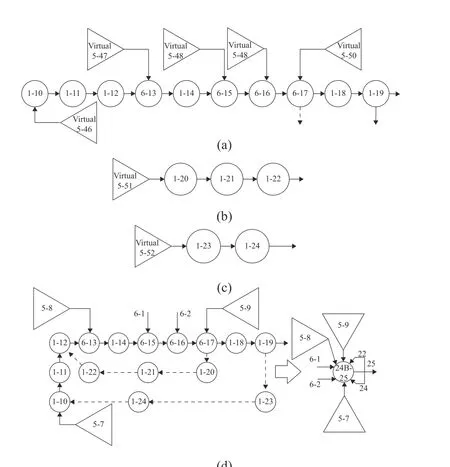
Fig. 5 GO model with five-input double-closed-loop feedback links: (a) GO model of the output path C of the fiveinput double-closed-loop feedback structure;(b) GO model of the feedback path F1 of the five-input doubleclosed-loop feedback structure.; (c) GO model of the feedback path F2 of the five-input double-closed-loop feedback structure; (d) the form of the five-input double-closed-loop feedback links in the system GO model
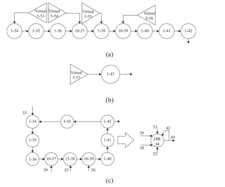
Fig. 6 GO model with four-input single-closed-loop feedback links: (a) GO graph model of the output path C of the fourinput single-closed-loop feedback structure; (b) GO model of the feedback path F of the four-input single-closedloop feedback structure; (c) the form of the four-input single-closed-loop feedback links in the system GO model

Tab. 2 Operator and reliability parameters of DFSS components

Fig. 7 GO model of fuel supply system
3.3 GO Operation
3.3.1 Perform Data Handling
The steady-state availability of each component is obtained according to Eq. (3), as is shown in the last column of Tab. 2. For the multi-input and multi-closed-loop feedback links in the system, the GO operation is performed according to the first-level GO graph model to obtain the availability of the equivalent output and feedback path structure of each closed-loop feedback link (see Tab. 3).

3.3.2 Quantitative Calculation of DFSS through GO method
In this paper, the common signal precision algorithm [13] of the GO method is used to perform the GO operation, during which the availability of each component in Tab. 2 and Tab. 3 is substituted into the GO model, and the system success probability is 0.989330.

Tab. 3 Availability of equivalent-output and feedback path structure with multi-input multi-closed-loop feedbacks in the system
3.3.3 Qualitative Analysis of GO Method for the DFSS
In the GO model, take any function operator and perform the GO operation under the assumption,so that its failure probability is 1 and that of other operators remains the same. If the failure probability of the system is 1, it indicates that the function operator is in a first-order minimum cut set. All the first-order minimum cut sets can be obtained until all function operators have performed the above operation. Then, take any two function operators except the first-order minimum cut set, also assuming that their failure probability is 1 and that of the other operators remains the same. If the failure probability of the system is 1, then these two function operators are the second-order minimum cut sets of the system until all pairs of operators that meet the conditions have performed the above operation.Similarly, the minimum cut sets in other orders can be obtained. Based on the above analysis,each component is a first-order minimum cut set of DFSS.
4 Analysis and Comparison of Results
The direct algorithm and the common signal correction algorithm [1] are used to conduct the GO operation, meanwhile the Monte Carlo simulation [14] with 1 million times is taken to obtain the success probability (shown in Tab. 4).

Tab. 4 System availability calculated through different methods
It can be seen from Tab. 4 that the results of the direct algorithm are smaller than those of the common signal exact algorithm and Monte Carlo simulation, indicating that if the common signals are not considered, it will result in a large error. The result through the method put forward in this paper nearly equals to that of the Monte Carlo simulation.
Using FTA [15,16] to conduct qualitatively analysis of the DFSS, the top event is its failure,the fault tree is shown in Fig. 8, and the description of the fault events is shown in Tab. 5.

Fig. 8 Fuel supply system fault tree
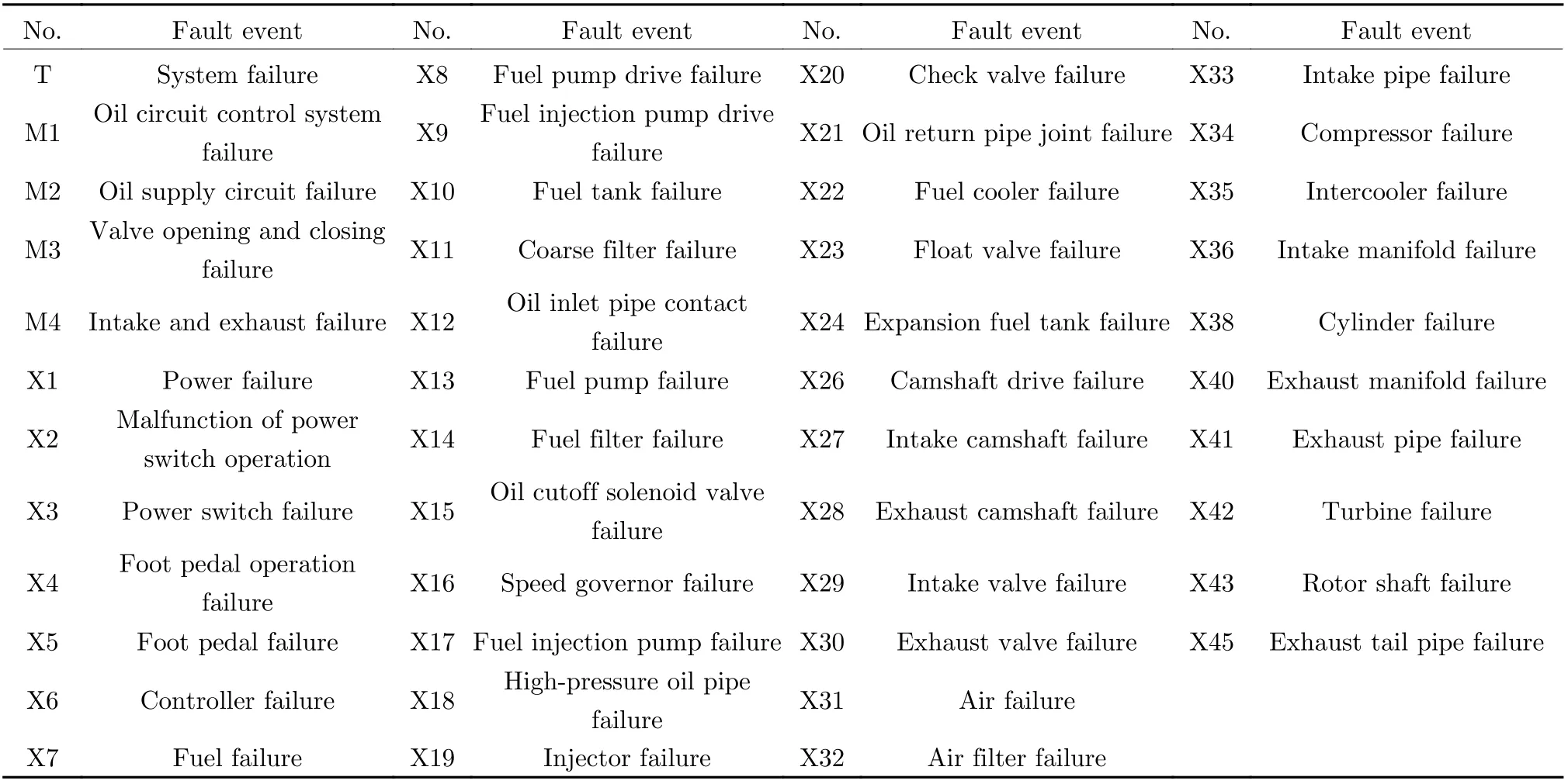
Tab. 5 Fault events in the fuel supply system fault tree model
It can be seen that each bottom event is a first-order minimum cut set, which is obviously consistent with the minimum cut set obtained through GO method.
5 Conclusion
A type-24B operator is proposed in this paper,which expands the types of GO method operators, solves the problem of reliability modeling of systems with multiple closed-loop feedback structures, and expands the application scope of research on GO method reliability.Comparing with the results obtained through the FTA and Monte Carlo simulation method, the usability and correctness of the type-24B operator proposed in this paper are verified for GO graph modeling and reliability analysis of complex systems with multiple closed-loop feedback links. It also shows that the GO method has unique preponderance in system modeling, qualitative analyses and quantitative algorithms.
杂志排行
Journal of Beijing Institute of Technology的其它文章
- Security Control for Uncertain Networked Control Systems under DoS Attacks and Fading Channels
- Blood Glucose Prediction Model Based on Prophet and Temporal Convolutional Networks
- Fault Diagnosis Method Based on Xgboost and LR Fusion Model under Data Imbalance
- An Improved Repetitive Control Strategy for LCL Grid-Connected Inverter
- Event-Triggered Moving Horizon Pose Estimation for Spacecraft Systems
- A Causal Fusion Inference Method for Industrial Alarm Root Cause Analysis Based on Process Topology and Alarm Event Data
