Optimal patching locations and orientations for maximum energy harvesting efficiency of ultrathin flexible piezoelectric devices mounted on heart surface
2022-08-26YngyngZhngJiWngChofeng
Yngyng Zhng , , Ji Wng , Chofeng Lü ,
a Faculty of Mechanical Engineering and Mechanics, Ningbo University, Ningbo 315211, China
b College of Civil Engineering and Architecture, Soft Matter Research Center, and Key Laboratory of Soft Machines and Smart Devices of Zhejiang Province,Zhejiang University, Hangzhou 310058, China
Keywords:Biomechanical energy harvester Flexible electronics Heart motion Myocardial strain
ABSTRACT Flexible piezoelectric energy harvesters (PEHs) have gained lots of attention in recent years, because of their potential biomechanical applications, such as powering implantable devices. Several in vivo animal experiments have demonstrated that the output power of a flexible PEH varies remarkably with patching orientations and locations, but the underlying mechanism remains unclear yet. Herein, an electromechanical model for a flexible PEH installed on a beating heart is proposed, and a concise relationship between the output power of the device and myocardium strain is established. The results demonstrate that the patching orientations have a significant impact on the output power of the PEH, and the optimal patching orientations for all patching locations are approximately 15–20 degree for PEHs mounted on the left ventricle. The simple theoretical method provided here would be universally effective for choosing the optimal patching locations and orientations of flexible PEHs installed on a nonhomogeneous deformed surface.
Energy harvesting from hearts has attracted researchers’ interest for several years owing to its potential to power implantable devices. Parsonnet et al. attempted to power pacemakers with biologic energy as early as 1963, barely five years after the invention of the cardiac pacemaker. They employed piezoelectric ceramic crystals to convert the pulsation of the aorta (the great arterial trunk that carries blood from the heart) to electric power,and successfully stimulated the heart of a dog with complete heart block disease [1] . Pacemakers were powered with batteries at that time. A pacemaker must be surgically replaced every five years due to the depletion of the battery. After years of progress, great enhancements have been achieved in pacemakers’ energy consumption and batteries’ energy density; however, a cardiac pacemaker still has to be replaced every 7–10 years due to battery depletion [2] . Moreover, the battery takes approximately 2/3 of the total weight of a cardiac pacemaker, imposing additional burden on users [3] . As a result, researchers have been investigating several energy harvesting methods from heart beatinginvitro[4–6] orinvivo[ 7 , 8 ] to power implantable devices (especially cardiac pacemakers) in the last decades.
Flexible piezoelectric energy harvesters (PEHs) with excellent mechanical and electrical properties have been fabricated and tested usinginvivoanimal experiments with the advancement in material science and nanotechnology [ 9 , 10 ]. As early as in 2010, a single ZnO nanowire was implanted into a live rat to harvest electric energy from heart beating [11] . To improve the output power efficiency, PEHs with a thin film structure were fabricated and then installed on bovine, ovine, or porcine hearts to harvest electrical energy [12–17] . Researchers found that patching locations and orientations have significant impacts on the electrical performance of the PEHs ( Fig. 1 ). For example, Dagdeviren et al. found that the voltage amplitudes are 3.8, 4.6, 1.6 V when patching orientations are 0 °, 45 °, and 90 °, respectively ( Fig. 1 a) [12] . Lu et al.[13] demonstrated that the voltage amplitudes of a PEH changes from 0.2 V to 1.5 V, when the patching locations in the experiments are changed. Meanwhile, Li et al. [17] showed the performance of the harvester is impacted greatly by the patching locations ( Fig. 1 b). The influence of patching locations and orientations of flexible energy harvesters have also been observed in triboelectric energy harvesters patched on hearts [ 18–20 ].
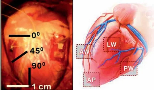
Fig. 1. Flexible piezoelectric energy harvester patching on hearts: ( a ) With varying patching angles; ( b ) With varying patching locations.
The underling mechanism of the impact of patching locations and orientations of flexible PEHs on their electric performance is still unclear. Zhang et al. [ 21 ] suggested the myocardial fibers’ orientation to explain the effect of patching orientations. However,two disadvantages exist in this model. First, it assumed that the hearts’ surface is under a unidirectional strain state, while the echocardiography findings demonstrate that the heart is under a complex strain state [ 22 , 23 ]. Second, this model is unable to analyze the effect of patching locations.
To address this research gap, an analytical model combined the strain distribution of left ventricle is proposed to analyze the influence of patching locations and orientations simultaneously on the electric performance of PEHs in this study. An electromechanical model is developed to calculate the output voltage of a PEH from its end-to-end displacement. Then the relationship between the end-to-end displacements of the PEH patched with varied orientations and the strain of the heart is constructed. Employing the reference values of the left ventricular strain in several patching locations from medical literature, the end-to-end displacements and the output power of PEHs patched at various locations with varied orientations can be calculated and compared.
The PEH (the initial length of the device isL0 ) is sewed onto the LV myocardial wall, with the two ends of the device being clamped. When a compression end-to-end displacementΔLis applied, the device undergoes a post buckling deformation ( Fig. 2 a).The out of plane displacementwof the PEH can be described as[ 24 ]
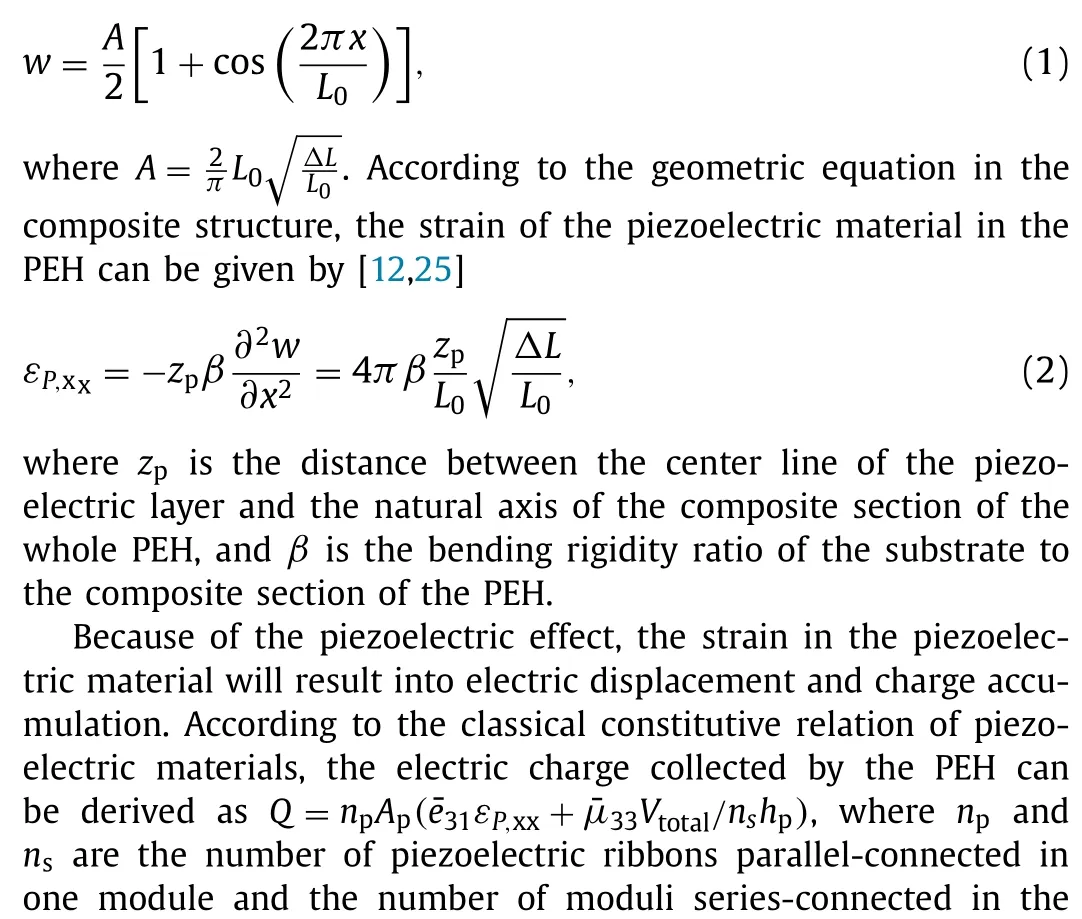
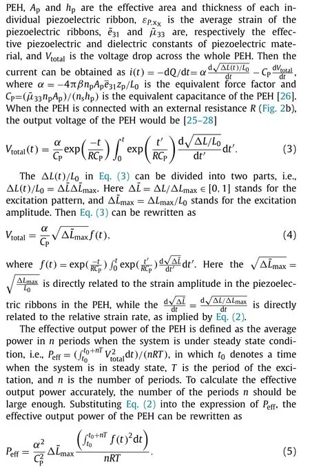
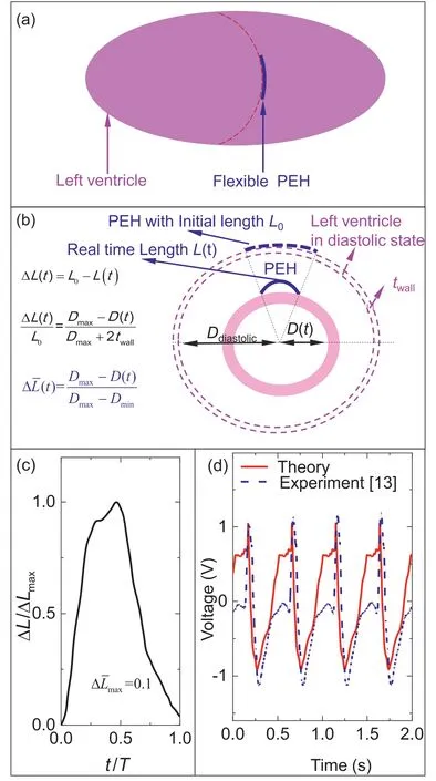
Fig. 3. Flexible piezoelectric energy harvester patched on heart: ( a ) Schematic illustration; ( b ) End-to-end displacement of the harvester imposed by the heart deformation; ( c ) Excitation pattern Δ¯L versus t/T ; ( d ) Comparison of output voltage signals between theory and the experiment conducted by Lu et al. [13] .
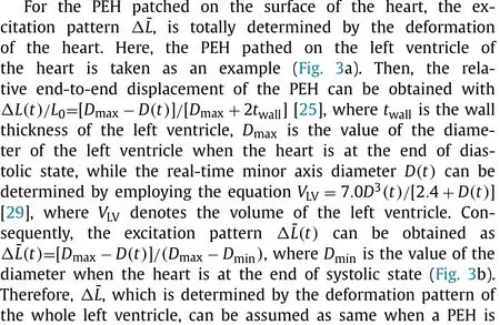
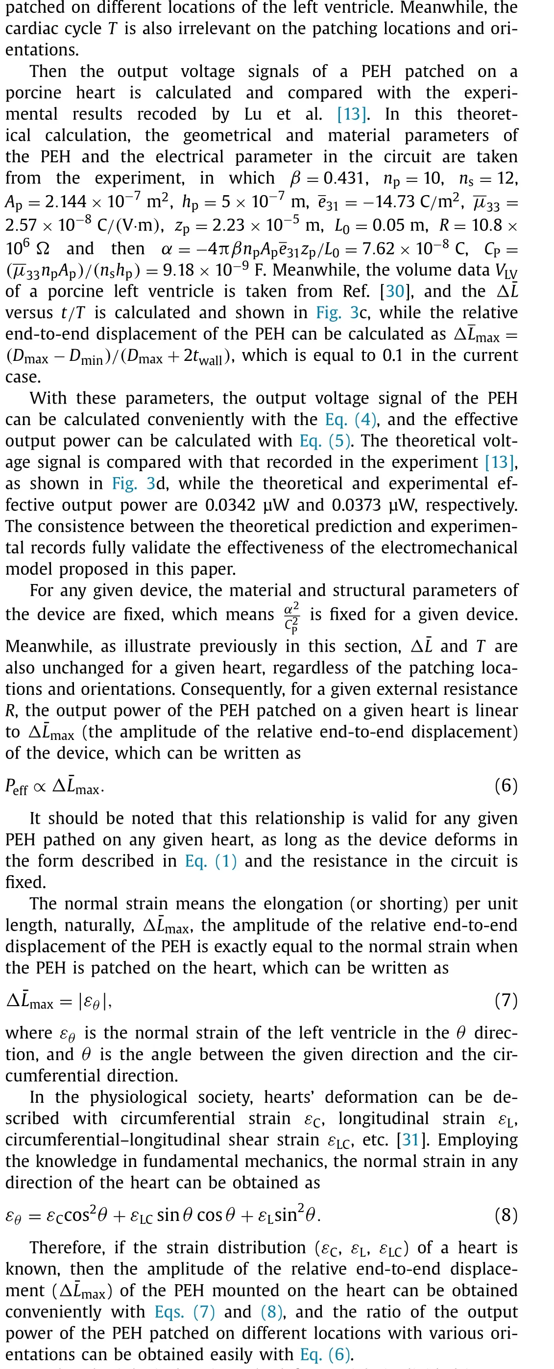
In the physiological society, the left ventricle is divided into 17 segments [ 32 ], and strain in all segments has been accessed usingthree-dimensional speckle tracking echocardiography [ 22 , 23 ]. The anterior, anterolateral, inferolateral, and inferior segments can be patched with the flexible PEH depending on the practical limitations. Here the anterior segment is used as an example, and the strain in this segment is listed in Table 1 .

Table 1 Strain in the anterior segment of left ventricle [ 22 , 23 ].
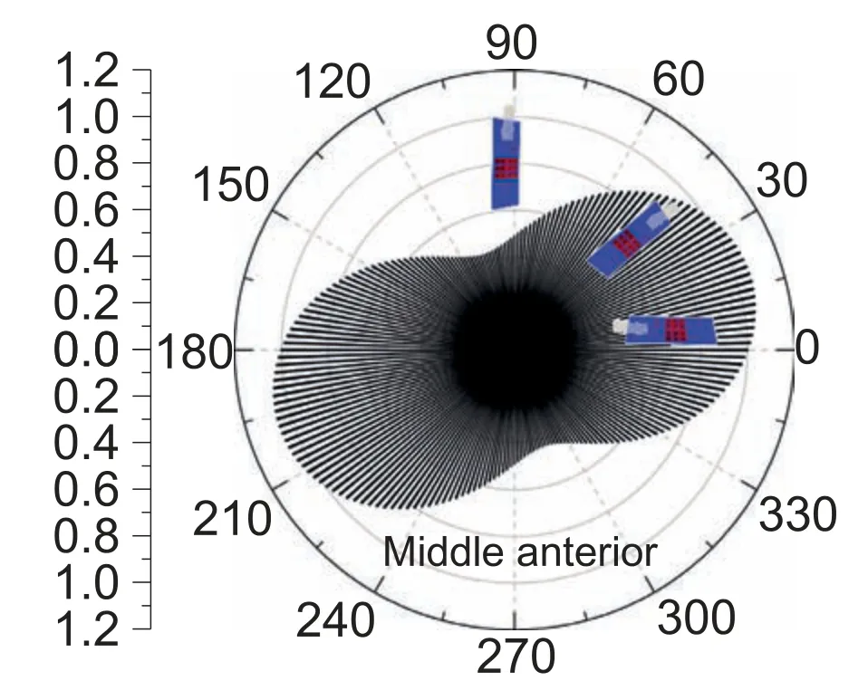
Fig. 4. Relative ratio of output power of the harvester pathed on the middle anterior segment with various directions.
The middle of the anterior segment is one of the most convenient places to patch the PEH, as a result, the output power of the PEH patched on this place along the circumferential direction is set as reference value. It is easy to collect the relative ratio of the output power of the PEH on other segments along any given direction by employing the method.
Figure 4 demonstrates the relative ratio of output power of the PEH pathed on the middle anterior segment with various directions. When the value of the direction is zero, which determines the PEH patches along the circumferential direction, the relative ratio of the output power equals to 1, since the output power of the PEH patched on this place along this direction is set as a benchmark. As the value of direction increases, the relative ratio of output power increases at first to achieve the maximum value,and then decreases. When the direction value is approximately 20 degree, the relative ratio achieves maximum value, which is 1.06.On the contrary, the relative ratio achieves minimum value (0.43)when the direction is approximately 110 degree.
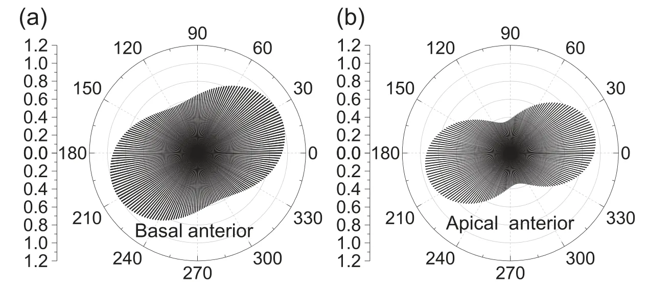
Fig. 5. Relative ratio of output power of the harvester pathed on the basal anterior segment and apical anterior segment.
Figure 5 demonstrates the relative ratio of output power of the PEH pathed on the basal anterior segment and apical anterior segment. For the basal segment, the maximum relative ratio is 1.02 while the optimal direction is approximately 25 degree, while the minimum relative ratio is 0.58 with the worst patching direction being 115 degree. For the apical segment, the maximum relative ratio is 0.96 while the optimal direction is approximately 15 degree, while the minimum relative ratio is 0.35 with the worst patching direction being 105 degree.
Figure 6 demonstrate the relative output power of the PEH patched on the middle anterolateral segment, the middle inferolateral segment, the middle inferior segment, and the apical inferior segment, respectively. It can be seen that the output power of the PEH patched on these segments shows minor changes. This may be due to the strain distribution data of these segments exhibits slight varieties [ 22 , 23 ].
The optimal and worst patching orientations for all the 12 available segments are shown in Fig. 7 . Figure 7 a shows the optimal patching angles for the 12 segments. It can be seen that the optimal segments are the middle inferior segment and apical interior segment, while the optimal pathing angles are 20 degree and 15 degree, respectively. Meanwhile, among all of these segments, the minimum output power ratio is 0.96, while the maximum value is 1.08. As a result, the patching locations have slight impact on the maximum output power. Figure 7 b shows the worst patching angles for 12 segments. It can be seen that the PEH harvests minimum energy when the PEH is patched on the apical anterior segment as the patching angle is 105 degree. This suggests that PEHs should not be patched with this patching orientation in application.
By comparing the results from Figs. 4–7 , it is discovered that the pathing orientations have a significant impact on the output power of the PEH. For example, when the PEH is patched on the apical anterior segment, the maximum value (0.96) is approximately 2.74 times of the minimum output power (0.35) as the patching orientation varies. However, the impact of the patching locations (segments) is slight and negligible. For example, when the PEH is patched on various segments with optimal angles, the minimum relative output power ratio is 0.96, approximately 89 %of the value (1.08) when PEH is patched on the optimal patching segment. This is because the strain distribution data has been averaged across location while employing the three–dimensional speckle tracking echocardiography [ 22 , 23 ]. In other words, the impact of the patching locations would be revealed if the highresolution strain distribution data are available.
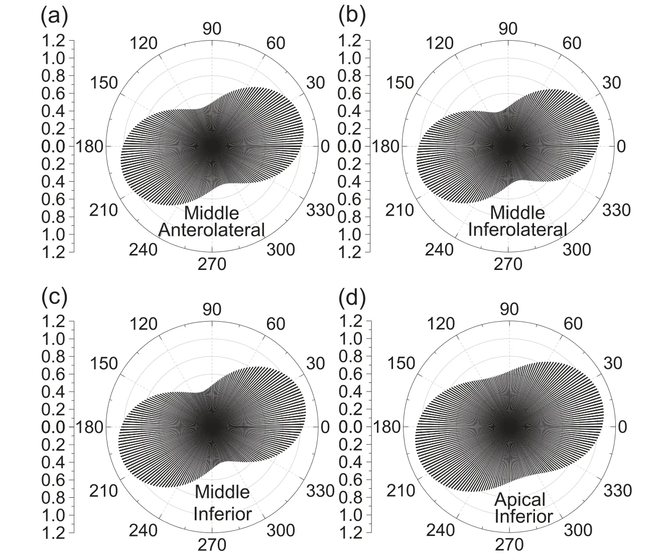
Fig. 6. Relative output power of the harvester patched on the middle anterolateral, inferolateral segment, inferior segment, and the apical inferior segment.
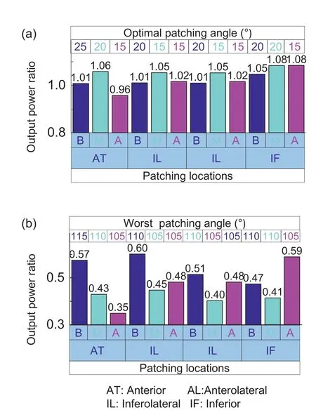
Fig. 7. Optimal and worst patching orientations for 12 segments of left ventricle.
A simple theoretical model is proposed for predicting the output power of a PEH patched at various angles and location. The effective output power of a PEH is linear to the devices’ relative endto-end displacement, which is precisely equal to the normal strain of the heart myocardium, according to careful deduction. A PEH patched on 12 segments of the left ventricle with various patching angles is calculated to determine the relative output power ratio.The patching orientations are shown to have a significant impact on the PEHs’ output power, and the optimal patching orientations for all patching locations are approximately 15–20 degree, while the worst pathing orientations (which should be avoided in practice) are approximately 105–110 degree. Meanwhile, the effect of the patching locations is insignificant, which is due to strain distribution data in present echocardiography has been averaged across location. It should be noted that this analytical model is universally valid for every PEH as long as the device experiences post-buckling deformation during a cardiac circle. The theoretical method and findings presented here could be used as guideline to determine the optimal patching locations and orientations for flexible PEHs installed a nonhomogeneous deformed surface.
Declaration of Competing Interest
The authors declared no potential conflicts of interest with respect to the research, authorship, and/or publication of this article.
Acknowledgements
Y. Z. acknowledges the financial supports by the National Natural Science Foundation of China (Grant No.11902168). J. W. acknowledges the financial supports by the Technology Innovation 2025 Program of Municipality of Ningbo (Grant No. 2019B10222).C.L. acknowledges the financial support by the National Natural Science Foundation of China (Grant No. 11925206).
杂志排行
Theoretical & Applied Mechanics Letters的其它文章
- Useful zero friction simulations for assessing MBS codes Pascal’s formula giving wheelsets frequency for zero wheel-rail friction
- Importance of induced magnetic field and exponential heat source on convective flow of Casson fluid in a micro-channel via AGM
- Optimal thermal design of anisotropic plates with arbitrary cutouts using genetic algorithm
- Similarity solutions of Prandtl mixing length modelled two dimensional turbulent boundary layer equations
- Numerical simulation of droplet coalescence based on the SPH method
- Thermal energy storage inside the chamber with a brick wall using the phase change process of paraffinic materials: A numerical simulation
