Speed planning and energy management strategy of hybrid electric vehicles in a car-following scenario
2022-07-06ShengyanHouHongChenYuZhangJinwuGao
Shengyan Hou·Hong Chen·Yu Zhang·Jinwu Gao
Abstract The development of intelligent connected technology has brought opportunities and challenges to the design of energy management strategies for hybrid electric vehicles.First,to achieve car-following in a connected environment while reducing vehicle fuel consumption, a power split hybrid electric vehicle was used as the research object,and a mathematical model including engine,motor,generator,battery and vehicle longitudinal dynamics is established.Second,with the goal of vehicle energy saving,a layered optimization framework for hybrid electric vehicles in a networked environment is proposed.The speed planning problem is established in the upper-level controller,and the optimized speed of the vehicle is obtained and input to the lower-level controller.Furthermore,after the lower-level controller reaches the optimized speed,it distributes the torque among the energy sources of the hybrid electric vehicle based on the equivalent consumption minimum strategy.The simulation results show that the proposed layered control framework can achieve good car-following performance and obtain good fuel economy.
Keywords Hybrid electric vehicle·Car-following·Speed planning·Energy management strategy
1 Introduction
With the increasingly serious environmental pollution and energy crisis,the development of the automobile industry in terms of energy conservation and environmental protection has been promoted, and new energy vehicles have become an inevitable trend for countries worldwide to upgrade the technology of the automotive industry[1,2].Among the new energy vehicles,although pure electric vehicles can achieve almost zero emissions,they are restricted by battery technology and have the problems of mileage anxiety,long charging time and short life span.Fuel cell electric vehicles(FCEVs)also have the advantages of pollution-free, high efficiency,and diverse fuel sources.However,the cost of fuel cells is relatively high,and there are technical problems in the storage and transportation of hydrogen. Therefore, the application of FCEVs is also limited. Hybrid electric vehicles (HEVs)have multiple energy sources(ESs),and while achieving low emissions and high energy savings, they also have strong endurance[3,4].Therefore,the research into HEVs will continue to be the top priority in the new energy vehicles research field.
The ESs of HEVs usually include mainly the engine and motor. Under the control of the vehicle controller, coordinated control of the engine and motor can be realized, and finally the engine can operate in the high efficiency range[5]. Therefore, the HEV reduces the fuel consumption and emissions of the vehicle, greatly improving. Since HEVs are composed of multiple ESs, energy management strategies (EMS) are the core key technology that affects the fuel economy of HEVs. The main goal of EMS is to reasonably distribute the output between the various ESs and optimize the operating range of the engine while meeting power requirements,so as to improve the economy and comfort of the vehicle. Existing EMSs can be divided into two categories:rule-based and optimization theory-based[6].
Rule-based EMSs (including deterministic rules, fuzzy control, etc.) use the experience of engineers or experts to design some simple rules to guide the energy distribution of hybrid power systems[7,8].Reference[9]proposed a rulebased hybrid EMS,which was formulated based on driving information and vehicle driving energy,rather than the usual vehicle speed profile.The simulation results showed that the performance of the EMS proposed in this paper was better than that of the traditional EMS.A fuzzy logic-based EMS for formulating power flow and torque distribution strategies has been developed in[10].The fuzzy logic controller was designed according to the state of charge(SOC)of the battery,the speed of the vehicle,the traction torque and the power demand of the vehicle.The simulation results showed that the proposed strategy can maintain the SOC in a better range while maintaining good economic efficiency.Although the rule-based EMS design is simple and easy to implement,when the driving conditions change,the results obtained may not be ideal.Considering the characteristics of each component,the results of these strategies are not optimal[3].
The optimization theory-based EMS describes the energy distribution problem in mathematical language.By defining the cost function and constraints of the optimization problem, the cost function is minimized to obtain the optimal control sequence.Reference[11]selected four typical driving modes as the database of driving conditions,obtained the optimal control strategies of the four driving modes based on the dynamic programming algorithm,and then extracted the mode transition control and power distribution method based on the obtained results. By introducing driving pattern recognition,an adaptive control strategy framework was proposed. The simulation results showed that the proposed adaptive strategy can appropriately adjust the power distribution in real time and can significantly improve the fuel efficiency of the HEV. A suboptimal EMS based on Pontryagin’s principle of minimum[12]takes into account fuel economy and power source durability.Meanwhile,a co-state updating method was developed according to the change of SOC.The comparison with the rule-based and the dynamic programming-based EMS showed the superiority of the proposed controller.
In recent years, with the rapid development of intelligent transportation systems(ITS)and vehicle to everything(V2X) technology, a new approach has been provided for the optimal control of the EMS of HEVs [13,14]. How to use connected information to optimize of EMSs for HEVs and further enhance the energy-saving potential of vehicles is the key to current research on intelligent connected vehicles [15,16]. In the car-following system, the ego vehicle can use sensors,radar and other technologies to obtain road traffic information ahead.The ego vehicle speed is planned in real time according to the relative speed of the ego vehicle and preceding vehicle and the headway distance,which effectively improves driving safety, mobility and economy.To extend the range of electric vehicles, a direct adaptive cruise control (ACC) control algorithm based on nonlinear model predictive control(MPC)has been proposed in[17].This algorithmsacrificedpart of thesafetyperformanceinthe followingprocesstooptimizethevehiclespeed,sotheenergy consumption of the drive system was reduced.Besides,the ACC control algorithm was simulated and verified in real driving conditions.The results showed that the energy consumption of electric vehicles in the process of following the vehicle can be reduced by appropriately shortening the distance between the preceding and ego vehicle,so as to extend the cruising range of the vehicle.Reference[18]proposed a hierarchical control structure of ACC system based on MPC algorithm.In the upper-level controller,the MPC algorithm is used to optimize the safety, tracking performance, comfort,and energy consumption during the driving process.The energy recovery of the electric vehicle during braking is carried out in the lower-level controller,and the optimal decision output of the upper-level controller is tracked by controlling the driving and braking system, so as to reduce the energy consumption of the electric vehicle during the following driving process and extend the range.Reference[19]proposed a game-theory-based longitudinal autonomous driving control framework.The longitudinal driving control is transformed into a multi-objective optimization problem including safety,economy, and comfort, and a game theory model is established to solve the multi-objective equilibrium problem. A control strategy based on game theory coordinates the electric motor, internal combustion engine and vehicle braking system to achieve a multi-objective balance.The simulation results show that the proposed framework can achieve better vehicle tracking while reducing fuel consumption and improving driving comfort.
Inspired by the above analysis,this paper studies the speed planning and EMS in the car-following scenarios in the connected environment, which are achieved through a layered optimization framework. First, in the upper-level optimization framework,according to the vehicle speed and distance information obtained by V2V communication,a speed planning model for the car-following scenarios is established.On the premise of knowing the speed of the preceding vehicle,the speed of the ego vehicle is optimized based on equivalent consumption minimum strategy (ECMS) algorithm.Additionally,the lower-level control system obtains the optimal EMS according to the speed planned by the upper-level controller.The proposed layered optimization framework is simulated and analysed in two actual driving cycles and a standard driving cycles. Finally, simulation analysis proves the superiority of the proposed layered optimization framework in terms of fuel economy.

Fig.1 The configuration of the HEV
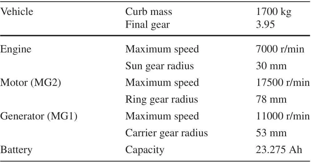
Table 1 Parameters of the HEV
In general, the following three main contributions are made by this paper.
(1) A nonlinear multi-objective optimal control framework is proposed for power-split HEV,which could optimize inter-vehicle safety and fuel economy simultaneously.
(2) To achieve stable and safe car-following functions,fuel consumption and driving comfort are considered in the speed planning layer; in the lower-level controller, the system state equation is simplified to reduce the complexity of solving the optimization problem.
(3) The proposed controller is evaluated at different driving cycles, such as urban driving and highway driving.Compared with the optimal results obtained by the DP algorithm,the energy saving effect is only 6-9%higher.
The rest of this paper is organized as follows:in the next section,the system configuration and powertrain model are introduced.Section 3 studies the layered optimization framework,which aims to plan speed of the ego vehicle and design the EMS.In addition,Sect.4 presents the simulation results and analyses of the proposed strategy under 3 driving cycles.Finally the main conclusions are summarized in Sect.5.
2 System description
The target vehicle configuration studied in this paper is a power split type,equipped with a planetary gear mechanism as a power splitter. The structure of the vehicle powertrain system is shown in Fig.1,and the parameters of the HEV are listed in Table 1. The core component of this type HEV is a power splitter.Its main structure is a single-row planetary gear configuration.Unlike traditional transmission gears,the planetary gear mechanism has the characteristics of multiple degrees of freedom and multiple inputs.In terms of function,it can replace the traditional transmission,realize the decoupling of vehicle speed and engine speed, with outstanding fuel-saving potential [20]. This paper takes the single-row planetary gear HEV as the research object,first establishing the HEV model,then laying the model foundation for EMS research.
2.1 Planetary gear system model
The planetary gear set structure can realize the engine in the powertrain system by adjusting the speed of one of the motors. Decoupling control with vehicle speed causes the engine to work in the high-efficiency speed-torque range[21].As shown in Fig.1,the single-row planetary gear coupling mechanism is mainly composed of three parts:the sun gear,the planetary gear carrier and the ring gear.The sun gear is connected to the generator MG1,and the planet carrier is connected to the engine ICE.The ring gear is connected to the motor MG2 and the torque is transmitted to the wheels through the final drive and differential[22].
The dynamics of planetary gear system can be summarized as

whereIedenotes the inertia of the engine and carrier gear,Igis the inertia of the generator and the sun gear,Imrepresents the inertia of motor and reduction,Fis the acting force on the ring gear and sun gear,Rt,Rc,RsandRrrepresent the radii of the tire,carrier gear,sun gear and ring gear,respectively,τe,τgandτmdenote the torque of the engine,generator and motor,respectively,ωe,ωgandωmdenote the speed of the engine,generator and motor,respectively,i fis the ratio of the final gear,andFdrrepresents the driving force at the wheel.
The relationship of the planetary gear system speed is as follows[23]:
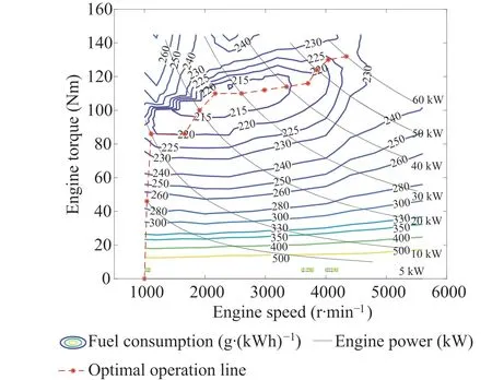
Fig.2 The engine BSFC map and OOL

2.2 Vehicle longitudinal dynamics model
Only the longitudinal driving condition and its control are considered,and the influence of lateral motion and handling stability is ignored. Based on this, a longitudinal dynamic analysis is carried out. The resistance of a vehicle during driving includes rolling resistance, air resistance, gradient resistance and acceleration resistance.The driving equation of a car can be expressed as:

wherevandMare the vehicle velocity and curb mass,μ,CD,g,α,A,andρare the rolling resistance coefficient,the frontal area,gravity acceleration,road slop,air drag coefficient,and air density respectively.
2.3 Engine model
The engine modeling usually includes the theoretical modeling and experimental modeling. This paper adopts an experimental modeling method, focuses more attention on the input and output characteristics of the engine, ignores the fuel consumption caused by the dynamic migration of the engine operating point,and uses the steady-state test data from the bench test to model the engine. The engine brake specific fuel consumption (BSFC) map and optimal operation line(OOL)are shown in Fig.2.
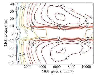
Fig.3 The efficiency map of the MG1
2.4 Battery model
Establishing a reasonable battery model and accurately expressing the relationship between various characteristic parameters are an important basis for optimal control of EMSs. Commonly used battery models include equivalent internal resistance model,Thevenin model,and second-order RC model[24].Among them,the battery equivalent internal resistance model has a relatively small amount of calculation, and can simply and accurately reflect the relationship between various characteristic parameters of the battery,and estimate the change of the battery SOC according to the current battery state variables to meet the needs of EMS.Therefore,this paper uses the equivalent internal resistance model to model the battery[25].The calculation of SOC is as follows:
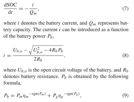
wherePmandηmare the output power and the efficiency of MG2 respectively,andPgandηgare the output power and the efficiency of MG1,respectively.The efficiencies of MG1 and MG2 are illustrated in Figs.3 and 4.
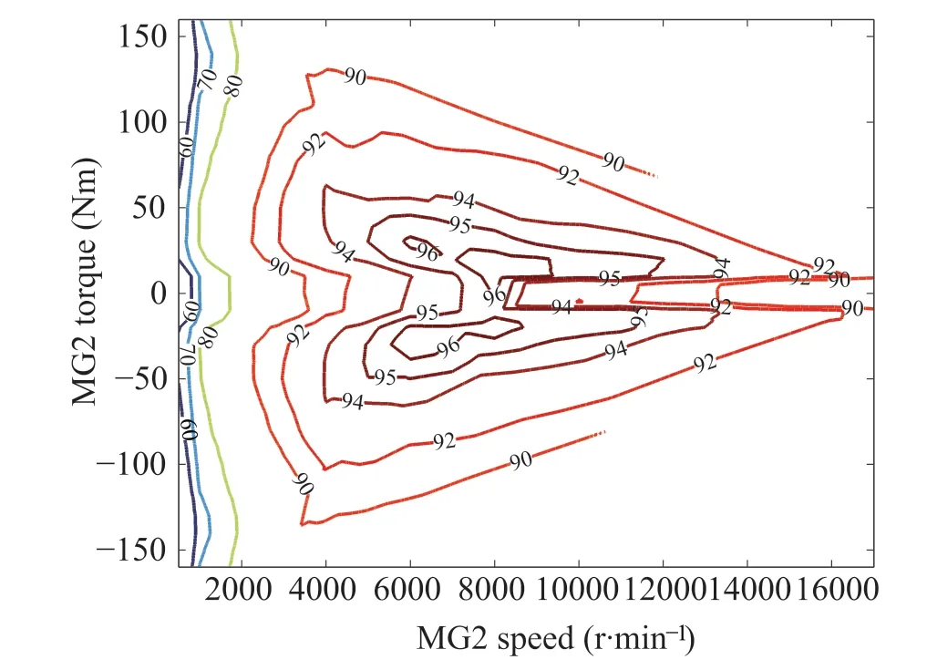
Fig.4 The efficiency map of the MG2
3 Layered optimization framework
In this section,a layered optimization framework under the car-following scenario is proposed. The upper-level controller is the decision-making control layer, which sets the speed of the ego vehicle based on the preceding vehicle dynamics and control objectives of the ego vehicle, and outputs it to the lower-level control unit. The goal of the upper-level controller is to minimize fuel consumption while ensuring a safe distance between vehicles. The lower-level controller is an online EMS based on the ECMS, which should achieve good fuel economy while limiting the SOC within the expected range.
3.1 Speed planning
The speed planning problem presented in this subsection is to use the known driving information of the preceding vehicle to plan the speed of the ego vehicle, to provide better ego vehicle economic efficiency and to ensure the safety of the car-following process. In the car-following scenario of this paper,the ego vehicle must follow the preceding vehicle at a fixed distance while both vehicles keep the same speed at this moment, after each optimization horizon ends. This problem is described as follows:on the premise of satisfying driving safety and power demand,an optimal speed trajectory is found to minimize the energy consumption over the whole optimization horizon[26].The distancestraveled by the ego vehicle and the speedvof ego vehicle are denoted as follows:

where the driving forceFdrand braking forceFbare control variables.
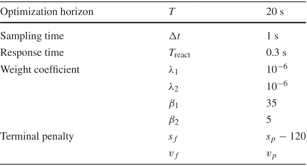
Table 2 Parameters in the speed planning algorithm
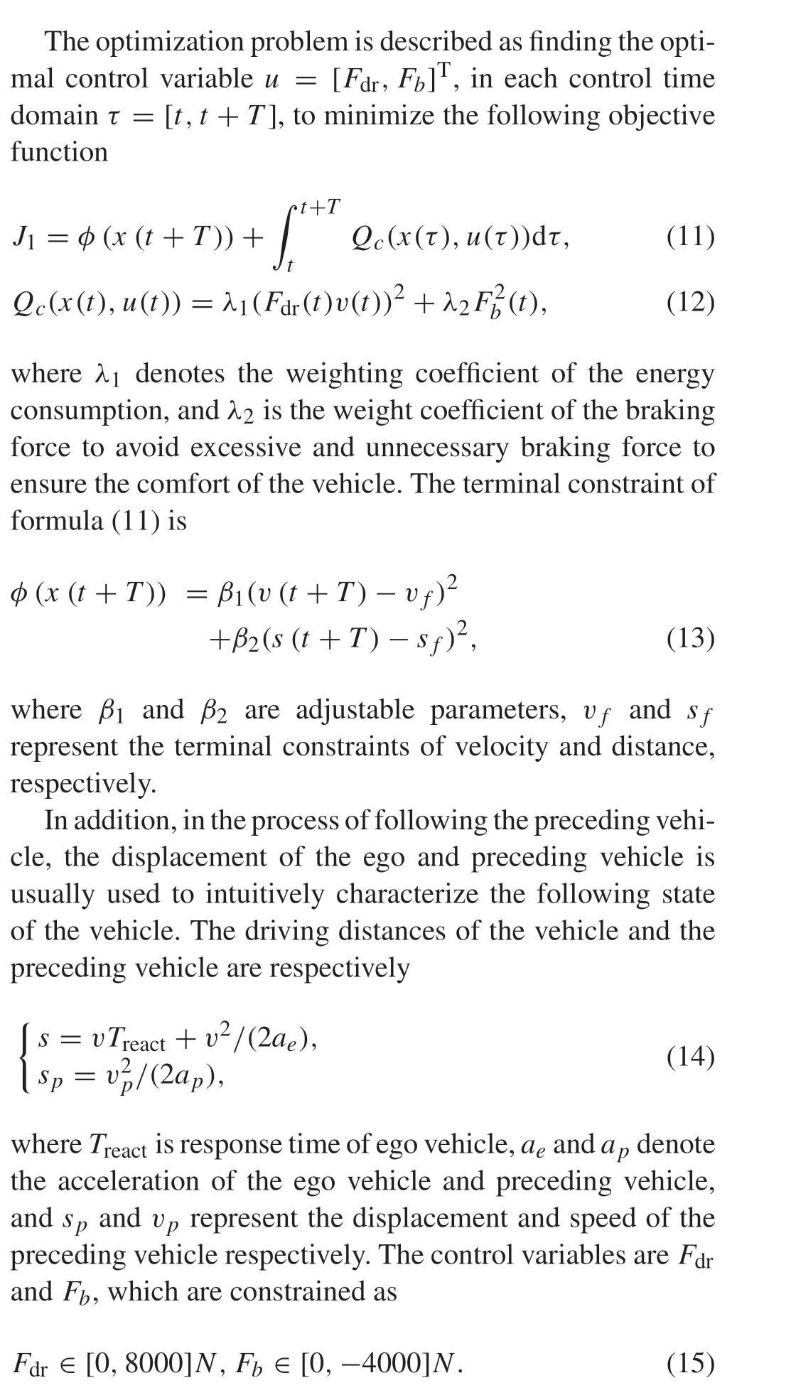
The value of the parameter used in the speed planning algorithm is in Table 2.
The ECMS algorithm is applied to calculate the control sequence to solve the speed planning problem,which will be introduced in the next section.
3.2 Energy management strategy
The ECMS is a heuristic method to solve the optimal control problem,which transforms the global optimization problem intoaninstantaneousoptimizationproblemanddoesnotneed to foresee the entire driving cycle [27]. The computational speed is faster and can be applied in real time. This paper applies the ECMS algorithm to distribute power between ESs.The algorithm converts the electric energy consumed by theMG1andMG2toequivalentfuelconsumptionthroughan equivalent coefficient,aiming to minimize the instantaneous equivalent fuel consumption to obtain the optimal control sequence [28]. This paper applies the ECMS algorithm to solve the optimal speed trajectory of the ego vehicle and fulfill the power balance between the demand power and power sources.
The equivalent fuel consumption of the EMS is defined in the following form:

whereNis total time of driving conditions, ˙m fand ˙mbatrepresent fuel consumption of the engine and equivalent fuel consumption the battery,f1 is the table lookup function forτe,ωe,Qlow=47000 kJ/kg is the low heating value of fuel,andγdenotes the equivalence factor,which is set to a constant in this paper.The dynamic of SOC through equations(7)and(8)is
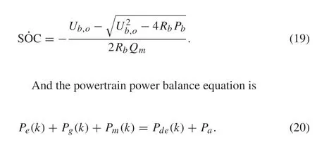
wherePg,Pde,Pm,andPaare the generator power,vehicle demand power, motor power, and auxiliary power, respectively. Moreover, the powertrain system should satisfy the following inequation constraints:
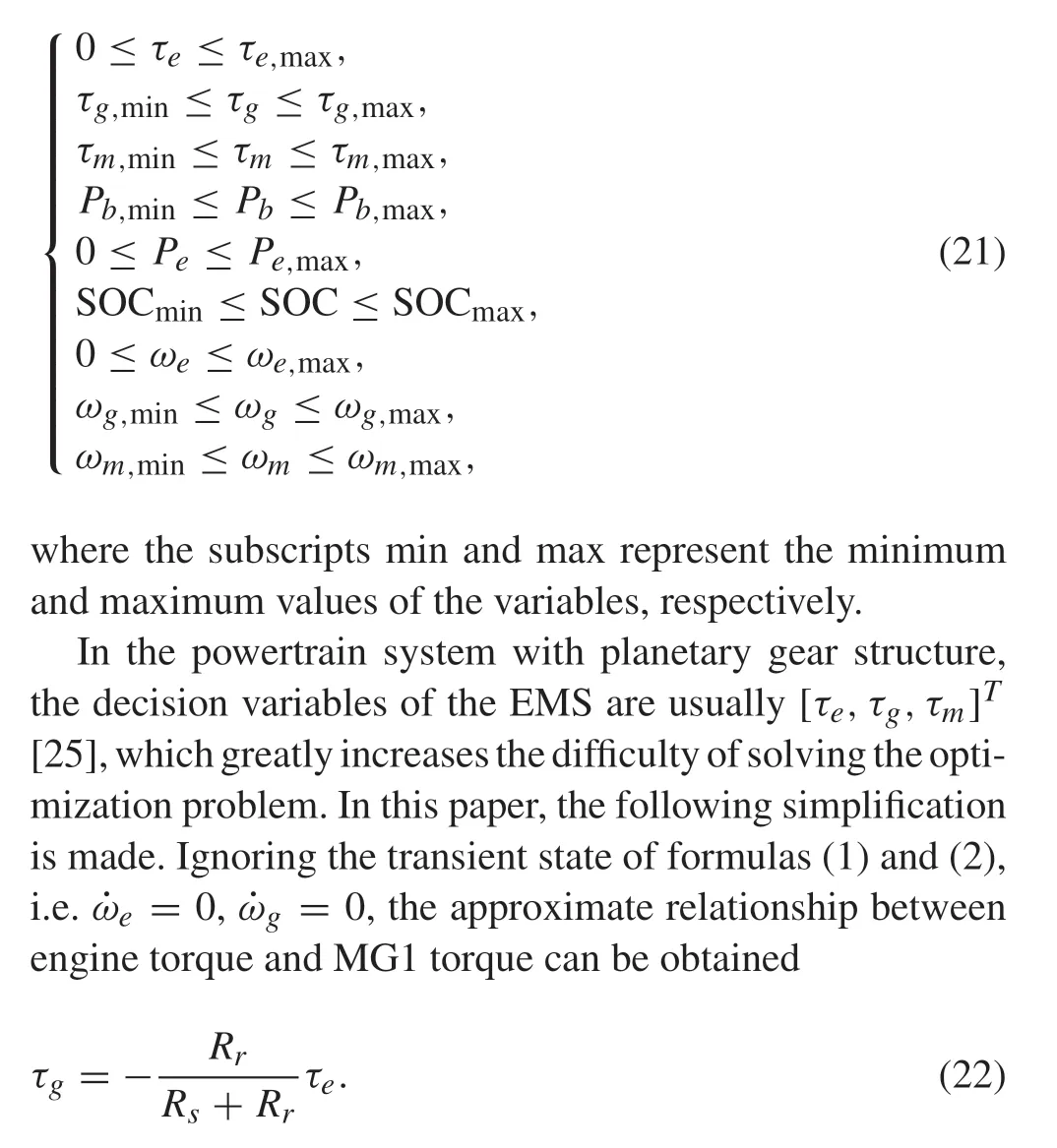
Additionally,to make the engine work as closely as possible to follow the OOL,while reducing the dimensionality of the system,it can be obtained by fitting the engine OOL
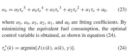
whereuthat is the control variable represents the engine torqueτe,andxthat is the state variable represents the SOC of the battery.
The algorithm block diagram proposed in this paper is shown in Fig. 5. The proposed optimization framework is divided into two levels. First, the ego vehicle speed is optimized in the upper-level controller and input to the lowerlevel controller.Then according to the speed and acceleration of the ego vehicle at this time, the working mode is determined: EV or HEV. The condition set in this paper is that when the vehicle speed is greater than 10 m/s or the acceleration is greater than 0.5 m/s2,the vehicle enters the hybrid drive mode,otherwise it is in the pure electric mode.
4 Simulation results
In this section,simulations are demonstrated to evaluate the effectiveness of the presented layered optimization frame-
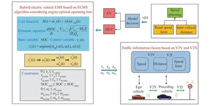
Fig.5 The layered optimization framework
work in a connected environment.In the car-following scene,the speed and distance of the preceding vehicle can be obtained through V2V,and the road speed limit information can be obtained through V2I.In the connected environment,the speed trajectory of the preceding vehicle gives three driving conditions,which are two actual road driving conditions and a standard cycle driving condition.The two actual driving conditions are obtained by automotive road tests in a montanic town area, which are provided by the conference organizers of the 6th IFAC E-COSM 2021 Benchmark Challenge [29]. And to verify the simulation results in more comprehensive driving condition, a driving condition with higher average speed, ARB02, is selected. All simulations are performed in MATLAB.
4.1 Car-following results under different driving conditions
The car-following simulation results are summarized in Figs. 6, 7, 8. The solid blue line is the speed of the preceding vehicle,and the red dashed line represents the speed of the ego vehicle optimized by the speed planning algorithm proposed in this paper.
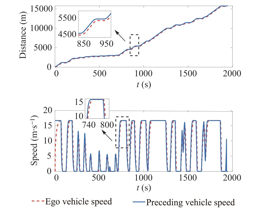
Fig.6 Speed and distance trajectories of the ego vehicle and the preceding vehicle in cycle1
In the two urban conditions,the speed trajectories of the ego vehicle and preceding vehicle are basically the same.In the initial stage of the driving condition,the initial speed of the preceding vehicle is 60 km/h,whereas the self-vehicle speed starts from 0,so there are some differences in the speed trajectory. In the rest of the time period, the speed trajectories of the ego vehicle and the preceding vehicle are not much different.However,the speed change rate of the egovehicle is smaller than that of the preceding vehicle,which improves the economy of driving. In the standard driving condition ARB02,the speed of the preceding vehicle has a greater change after 600 s,because the speed during this time period is higher.The speed trajectory planned in this paper has relatively stable speed changes, reflecting good driving performance.From the distance trajectories of the three driving conditions, it can be understood that in the above three driving conditions,the speed planning results of the ego vehicle can maintain a preset safe distance from the preceding vehicle.The running trajectories of the two vehicles do not overlap, indicating that the following distances are greater than zero,and the ego vehicle does not overtake or crash,thus a good car-following function has been realized.Besides,the trajectory of the ego vehicle changes more smoothly than that of the preceding vehicle,which means that the instantaneous acceleration of the ego vehicle is smaller,and there are fewer braking times of the ego vehicle during driving.These indicates that the speed planning algorithm proposed in this paper can realize the safe and stable operation of the vehicle and improve the economy of the vehicle.
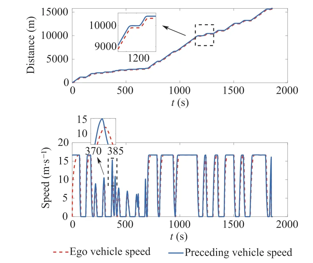
Fig.7 Speed and distance trajectories of the ego vehicle and the preceding vehicle in cycle2
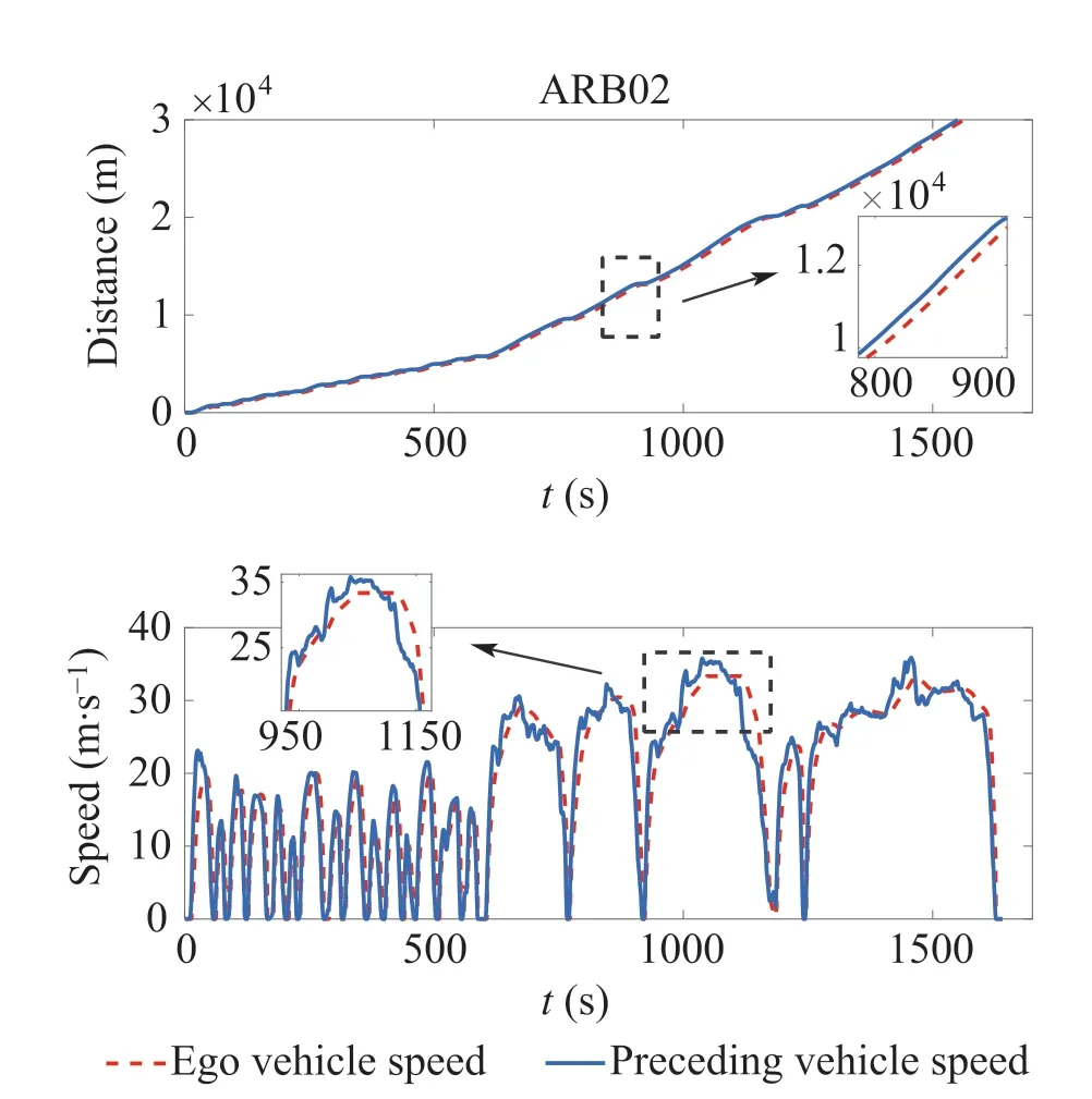
Fig.8 Speed and distance trajectories of the ego vehicle and the preceding vehicle in ARB02
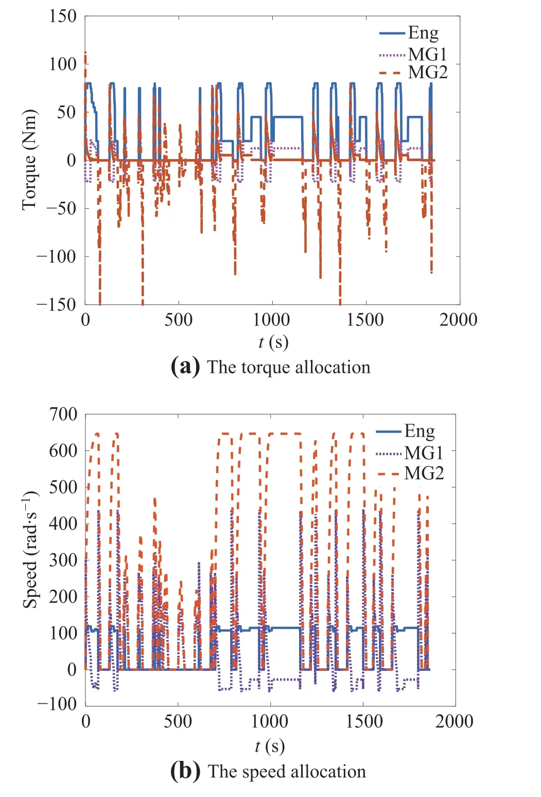
Fig.9 The torque and speed allocation of three energy sources in cycle2
4.2 Energy management strategy performance
After getting the speed optimized by the upper-level controller, the speed is input to the lower-level controller for energy distribution.This subsection presents the results of a few simulations to verify the validity of the proposed EMS.Because the preceding vehicle speeds of cycle1 and cycle2 are collected in the same road conditions, the energy optimization results of the two driving conditions are roughly the same. Therefore, only the specific results of cycle2 are analyzed below.Figs.9,10,11 show the specific simulation results in cycle2.Figure 9 contains the speed and torque distribution of the engine, generator, and electric motor. The torque distribution results show that at the starting stage,MG2 provides demanded power of the HEV.When the speed reaches 10 m/s or the acceleration exceeds 0.5 m/s2,the HEV enters the hybrid drive mode,and the engine starts to output power at this time.For example,in from 950-1000 s,MG2 outputs the power. The speed of MG1 fluctuates greatly, to adjust the engine speed to make it operate in a higher efficiency area, and the MG1 plays a role in speed regulation.From 1000-1200 s, only the engine and MG1 are working at this stage. The engine works in a higher efficiency area,and at the same time part of its energy is provided to MG1 to charge the battery,so that the SOC is maintained in a better working range.
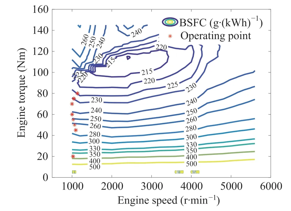
Fig.10 The engine efficiency map and operating points in cycle 2
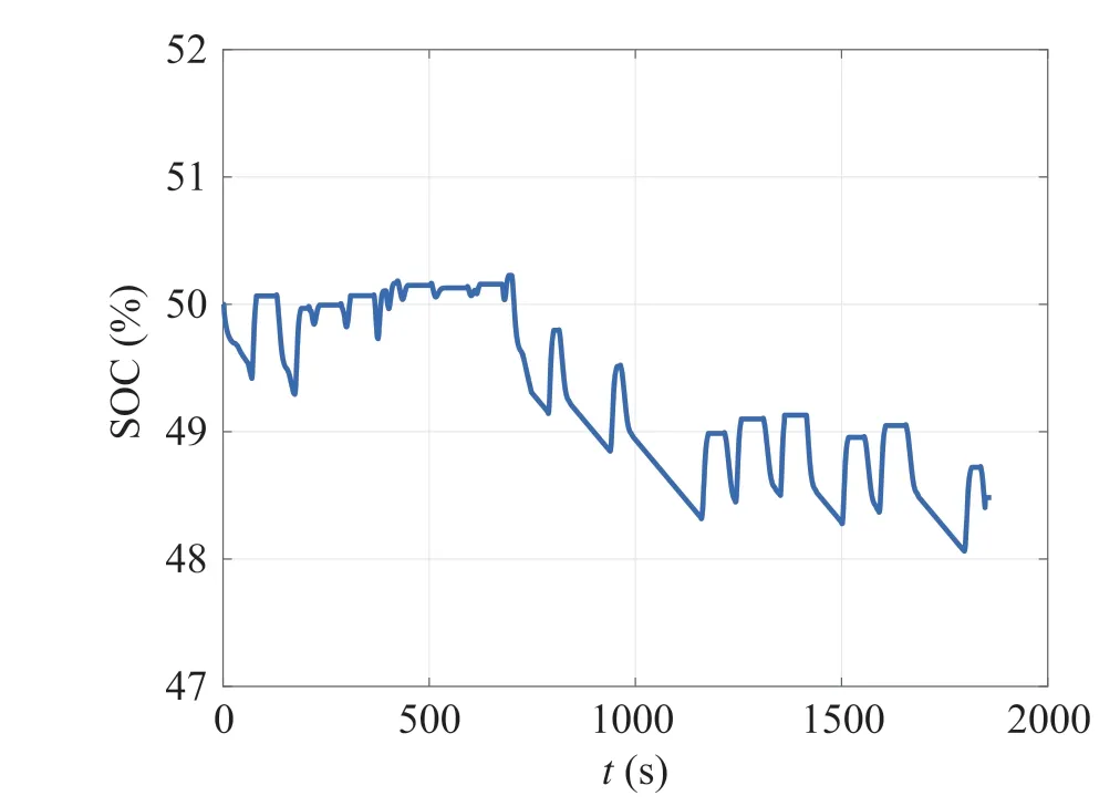
Fig.11 The SOC trajectory in cycle 2
Figure 10 depicts the engine efficiency map and operating points in the cycle2.The figure shows that the operating points of the engine follow the optimal operating line, but there are some differences from the optimal operating line in Fig.2,which is caused by errors in the fitting process.In addition, because cycle2 is an urban driving condition, the required power of HEV is low,so that the engine operating points are concentrated in the area below 15kW. Figure 11 covers the trajectory of SOC.From an overall point of view,the range of SOC change is small,concentrated between 48%and 51%,and the difference between the terminal and initial SOC also is small.
Figures 12,13,14 depict the specific simulation results in ARB02.Figure 12 covers the speed and torque distribution of the engine,generator,and electric motor.Figure 12a shows that during the driving process of the vehicle, the engine is basically turned on all the time, and there is no frequent startingandstopping,whichshowsagoodresult.Meanwhile,MG2 outputs more power in the vehicle’s starting phase.This is because the vehicle requires a large amount of power during acceleration,which causes the engine to work in the most efficient area and cannot meet the vehicle’s power requirements.Therefore,MG2 is required to supplement additional energy.In Fig.12b,the trajectory of MG2 speed is the same as the trajectory of the vehicle speed, and the relationship between the two is converted by final gear.The engine speed is concentrated between 1000-3000 r/min,which ensures the efficiency of the engine.And the speed of MG1 varies greatly because the speeds of the three energy sources are coupled.When the speed of MG2 is determined, MG1 needs to be changed to adjust the speed of the engine.
Figure 13 depicts the engine efficiency map and operating points in ARB02. The Figure shows that the engine operating point basically coincides with the best efficiency line and works in the highest efficiency zone, which improves the economy of the vehicle. Figure 14 shows the SOC trajectory in ARB02, the overall trend is to increase first and then decrease.In the first 600 s of the driving cycle,the average vehicle speed is low,so part of the engine output power is used to charge the battery.After 600 s,the vehicle speed gradually increases,which sends all engine power output to the wheels,while also requiring a battery discharge to provide the remaining power.Therefore,the terminal SOC stays at 43.21%.
To verify the effectiveness of the proposed method, the benchmark results obtained by the DP algorithm are compared with the results of ECMS.The fuel consumption with similar initial and final SOC of different algorithms is shown in Table 3. For fair comparison, the final SOC value optimized by the DP algorithm is set equal to that of the ECMS.However,due to the quantization accuracy of the DP,the final SOC of the two algorithms will have a small difference. In the first two driving cycles,the fuel consumption is about 390 g,and the terminal SOC is constrained to about 49%.As for DP,the fuel consumption under the two driving conditions is about 360 g.In cycle1 and cycle2,the fuel consumption of the method proposed in this paper is 8.50%and 9.06%more than that of DP,respectively.In the ARB02,and the terminal SOC stayed at 43.21%.Due to the high average speed of this driving cycle, the fuel consumption is 1,142.31 g. The fuel consumption under this driving cycle is much higher than the previous two because the distance of ARB02 is 31 km and the average speed is 70.04 km/h,while the distance of the two driving cycles is about 15 km and the average speed is about 30km/h.Furthermore,thefuelconsumptionoptimizedbythe DP in ARB02 is 1073.41 g. Compared to DP, it consumes 6.42%more fuel.Although the HEV consumes more fuel in ARB02,the energy-saving effect is better than the first twodriving cycles.As shown in Figs.10 and 13,because of the high power requirements of vehicles in ARB02,the engine works more in the high-efficiency area. While the HEV in cycle1 and cycle2 require lower power,and the engine operating points need to follow the best operating line,the engine efficiency in these two driving cycles is lower than the previous one.Finally,DP is a global optimization algorithm.In the EMS problem,it can get the optimal fuel consumption under a specific vehicle type.The fuel consumption calculated by the method proposed in this paper is 6-9% higher than the DP algorithm,which shows that the proposed algorithm can achieve fuel economy.

Table 3 Fuel consumption and SOC value under three driving cycles
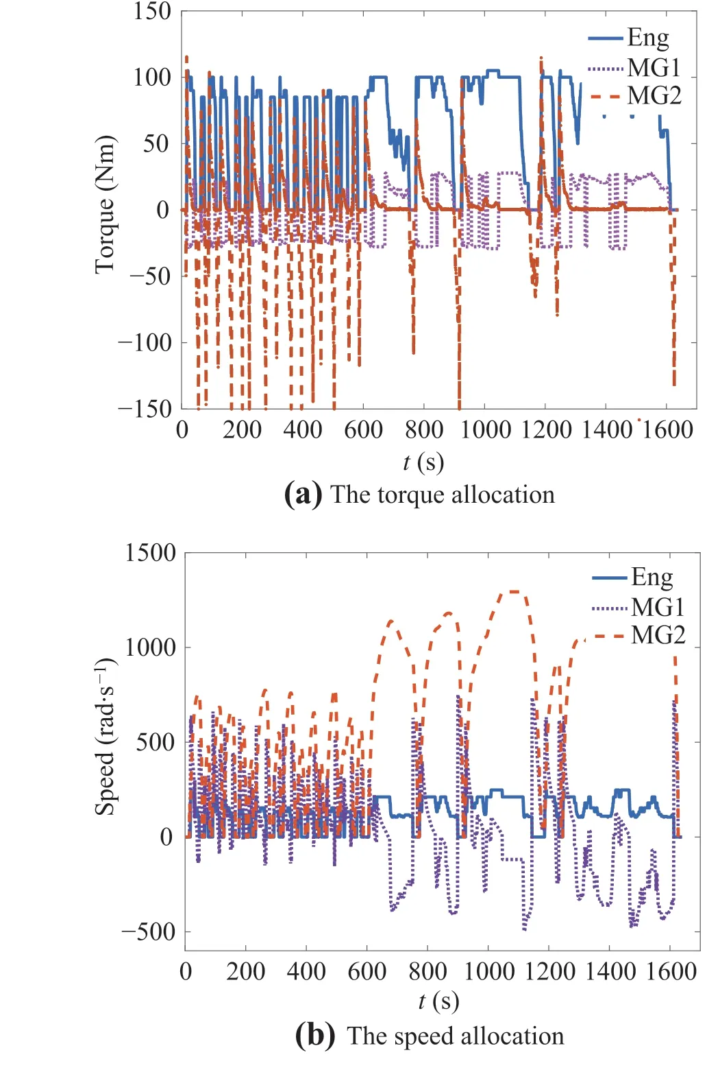
Fig. 12 The torque and speed allocation of three energy sources in ARB02
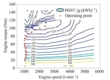
Fig.13 The engine efficiency map and operating points in ARB02
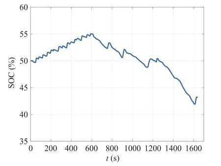
Fig.14 The SOC trajectory in ARB02
5 Conclusion
This paper takes the power split HEV as the research object,and proposes a layered optimization algorithm based on vehicle speed planning.Among them,the upper-level controller obtains the optimal speed from the goal of reducing vehicle energy consumption and avoiding frequent engine start and stop,and the lower-level controller designs EMS for the HEV according to the optimal ego vehicle speed.We conclude that the speed planning results of the ego vehicle can maintain a preset safe distance from the preceding vehicle,and the ego vehicle has no overtaking and collision phenomenon,leading to a good follow-up function.Moreover,under the premise of ensuring the stability of following the preceding vehicle,the SOC is maintained in a better range.Compared with the DP algorithm,fuel consumption is 6-9%higher,which reflects better fuel economy.
杂志排行
Control Theory and Technology的其它文章
- Stochastic model predictive braking control for heavy-duty commercial vehicles during uncertain brake pressure and road profile conditions
- Characterizing human driver characteristics using an artificial neural network and a theoretical model
- On-board torque management approach to the E-COSM benchmark problem with a prediction-based engine assignment
- Real-time energy optimization of HEVs under-connected environment:a benchmark problem and receding horizon-based solution
- Torque control strategy with V2X information for HEVs to minimize fuel consumption
- Optimization of fuel consumption and NOx emission for mild HEV via hierarchical model predictive control
