Restoring Polarization Angle Map for High-Fidelity Underwater Imaging
2022-04-29YimingLiLihengBian
Yiming Li, Liheng Bian
Abstract: Obtaining polarization information enables researchers to enhance underwater imaging quality by removing backscattering effect and to distinguish targets of different materials. However,due to the simplified assumption of unpolarized target light, most of the existing underwater polarimetric methods lose part of the polarization information, resulting in degraded imaging quality. In this work, a novel underwater polarimetric method is reported, which obtains the angle of polarization (AOP) map to improve imaging quality. Specifically, the Stokes vectors were exploited to remove the backscattering effect by obtaining two pairs of orthogonal polarization sub-images of the underwater scene. The target reflected light and the angle between the polarization directions of the target reflected light and the backscattered light were computed through the two groups of the orthogonal polarized sub-images. The AOP map of the target light could be derived from the Stokes vectors. Then, the transmission map of the target light was estimated by using the non-local color priorly combined with the properties of light propagating underwater. Experiments show that the reported technique enables distinguishing different targets when the colors are similar. The quantitative metrics validate that the reported technique produces state-of-the-art performance for underwater imaging.
Keywords: underwater imaging; polarization; angle of polarization (AOP); Stokes vector
1 Introduction
Underwater optical imaging is of great application value in such fields as marine resources exploration, seabed environment monitoring, marine search and rescue, and military reconnaissance, with the advantages of simple structure,direct image acquisition, and high image resolution. However, underwater suspended particles in the optical imaging path produce scattered light,some of which is scattered back to the detector,resulting in blurry and low-contrast underwater images.
Many methods have been put forward to improve the quality of underwater imaging. Some methods improve the visual quality of underwater images by image enhancement [1]. Bazeille et al. enhanced the contrast of underwater images through preprocessing, such as homomorphic filtering, wavelet denoising, anisotropic filtering,and color balance [2]. Hitam et al. effectively lessened noise by fusing the contrast limited adaptive histogram equalization (CLAHE) results in RGB space and HSV space [3]. Singh et al.also improved the imaging quality and eliminated color distortion using wavelet transform in conventional image enhancement methods [4]. C.Ancuti applied image fusion technology to underwater imaging and obtained expected results by taking two degraded images that had been preprocessed by color correction and filtering as the input of fusion [5].
Some methods take the reasons for image degradation into account and estimate parameters in the imaging model [6, 7]. Concerning the estimation of transmission, these methods could be divided into two sub-categories. The first subcategory takes the statistical properties of the natural environment as prior information. [8–11]came up with generalization dark channel prior,red channel prior, maximum intensity prior and non-local color prior respectively to estimate the transmission. However, the above methods could only be applied to a single environment. To expand the application scope of prior properties of natural images, [12–15] made improvements thereon, to better adapt them to different underwater environments. The second sub-category estimates the transmission using the method of polarization. Schechner et al. [16] advanced a classical underwater polarization imaging model to estimate transmission by calculating the degree of polarization (DOP) of backscattered light and then inverting and restoring the images with enhanced contrast by the underwater imaging model. On this basis, [17, 18] improved the accuracy of image restoration using approaches, such as polynomial fitting and histogram stretching.
The existing polarimetric imaging models often assume that the target reflected light is unpolarized or that the DOP of the target light is not zero but do not consider the angle of polarization (AOP). However, in practice, the target light is always partially polarized and its DOP and AOP are different from those of the backscattered light. This makes it impossible to obtain the ideal polarization sub-image by rotating the polarizer, losing part of the polarization information of the target reflected light, and thus the existing methods could cause significant estimation errors.
In this work, a novel underwater polarization imaging method that enables the restoration of the AOP of the target light is proposed to improve the image quality. We obtain two pairs of orthogonal polarization sub-images of the scene by rotating the analyzer in front of the detector under the condition of active polarization illumination. Using polarization difference between the target light and the backscattered light could remove the effect of the backscattering. The target reflected light and the angle between the polarization directions of the target reflected light and the backscattered light were computed through the two groups of the orthogonal polarized sub-images. The AOP map of the target light could be derived from the Stokes vectors. Then, the transmission map of the target light was estimated by using the non-local color priorly combined with the properties of light propagating underwater. The experiments reveal that the reported technique could distinguish different targets when the colors of the targets are similar. The quantitative metrics verify that the reported technique has state-of-the-art performance on image restoring.
2 Materials and Methods
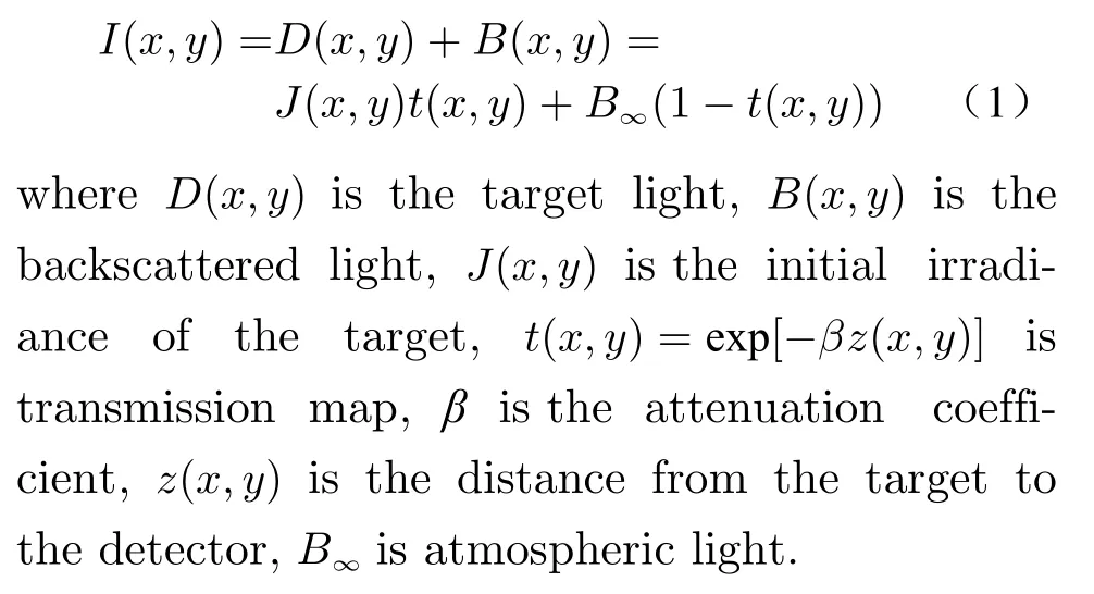
The underwater imaging model is
2.1 Polarization

Fig. 1 The imaging system in which the incident light is modulated by polarizer and then irradiated on the target,reflected by the target and received by the detector together with the backscattered light
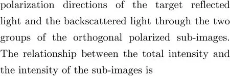
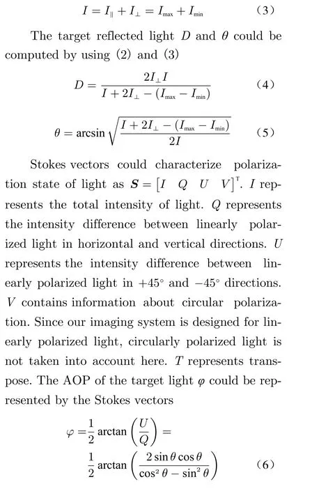
As shown in Fig. 1, our imaging system is an active polarization imaging system. The light source is a halogen tungsten lamp with a wavelength range of 360 – 3 800 nm which is closer to the real underwater situation. A linear polarizer is added behind the light source to adjust the polarization state of the incident light. The polarization direction of backscattered light is the same as that of the incident light when the scattering angle is wide [19]. For convenience, we adjust the incident light to horizontal linearly polarized light. The light received by the detector consists of two parts. The first part is the target reflected light, and its polarization direction is shown in Fig. 1.θis unknown which represents the angle between the polarization direction of the target reflected light and the horizontal direction.The second part is the backscattered light whose polarization direction is horizontal. A polarization analyzer is added in front of the detector.We obtained two pairs of orthogonal polarization sub-images of the scene by rotating the analyzer. According to Malus’s Law, the polarization formulation of the two pairs of orthogonal polarization sub-images acquired by the detector is

2.2 Transmission Estimate
According to (1),D(x,y)=J(x,y)t(x,y). To figure outJ(x,y), we have to estimate the transmission mapt(x,y). Inspired by [6], we combined the non-local color priorly with the properties of light propagating underwater to estimate thet(x,y).
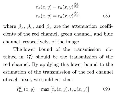
Since the irradianceJ(x,y)≥0, according to(1), the lower bound of transmission map is found

wheretLB(x,y) means the lower bound of transmission map at (x,y) pixel.Cmeans channels of images.Ris red channel,Gis green channel, andBis blue channel.Ic(x,y) is captured image. The transmission map of the red channeltR(x,y) is often the smallest among the three channels, since the effect of the absorption is intensified with increasing wavelength. The transmission map of the green channel and the blue channel could be represented by that of the red channel as
The transmission of the image is smooth in the continuous depth region. It is reasonable to

Fig. 2 shows the effect of the transmission map before and after optimization. As can be seen, the background and the target in the transmission map without optimizing is rough which will affect the quality of subsequent recovery.The transmission map after optimizing is smooth in the continuous depth region. It is reasonable to expect that the region of the transmission map corresponding to the smooth region of the image should be smooth as well.

Fig. 2 Effect comparison experiment of the transmission map before and after optimization
3 Experiments and Discussion
To verify the effectiveness of the reported technique, we designed the following experiments. We used a transparent polymethyl methacrylate water tank with a volume of 20 cm × 20 cm × 20 cm,poured half of the water into the tank, and placed a toy car and a coral in water as underwater targets. We put 20, 40, and 60 drops of milk into the water tank. Fig. 3 shows the recovered images and the AOP maps of the scenes under different turbid conditions. It can be seen from Fig. 3 (c) and Fig. 3 (f) that the concentration of milk does not affect the distribution of AOP.However, as the concentration increased, the irradiance on targets is decreased. Since the calculation of the AOP requires the irradiation of incident polarized light, there would be errors in the AOP where the incident light irradiates not much.

Fig. 3 Experimental results under different turbidities: (a) input images in which the target is the toy car; (b) the corresponding recovered images; (c) the corresponding AOP maps; (d) input images in which the target is the coral; (e) the corresponding recovered images; (f) the corresponding AOP maps
In some cases where the targets have similar colors, the AOP maps could distinguish targets of different materials. We designed a scene containing multiple targets with similar colors and observed the distribution of the AOP. As can be seen in Fig. 4 (a), since the warning lamps on the left and right of the car are made of the same material, their AOP values are the same, though their colors are different. In Fig. 4 (b), it is difficult to distinguish the overlapping part of the toy car and the coral from the recovered image due to their similar colors.
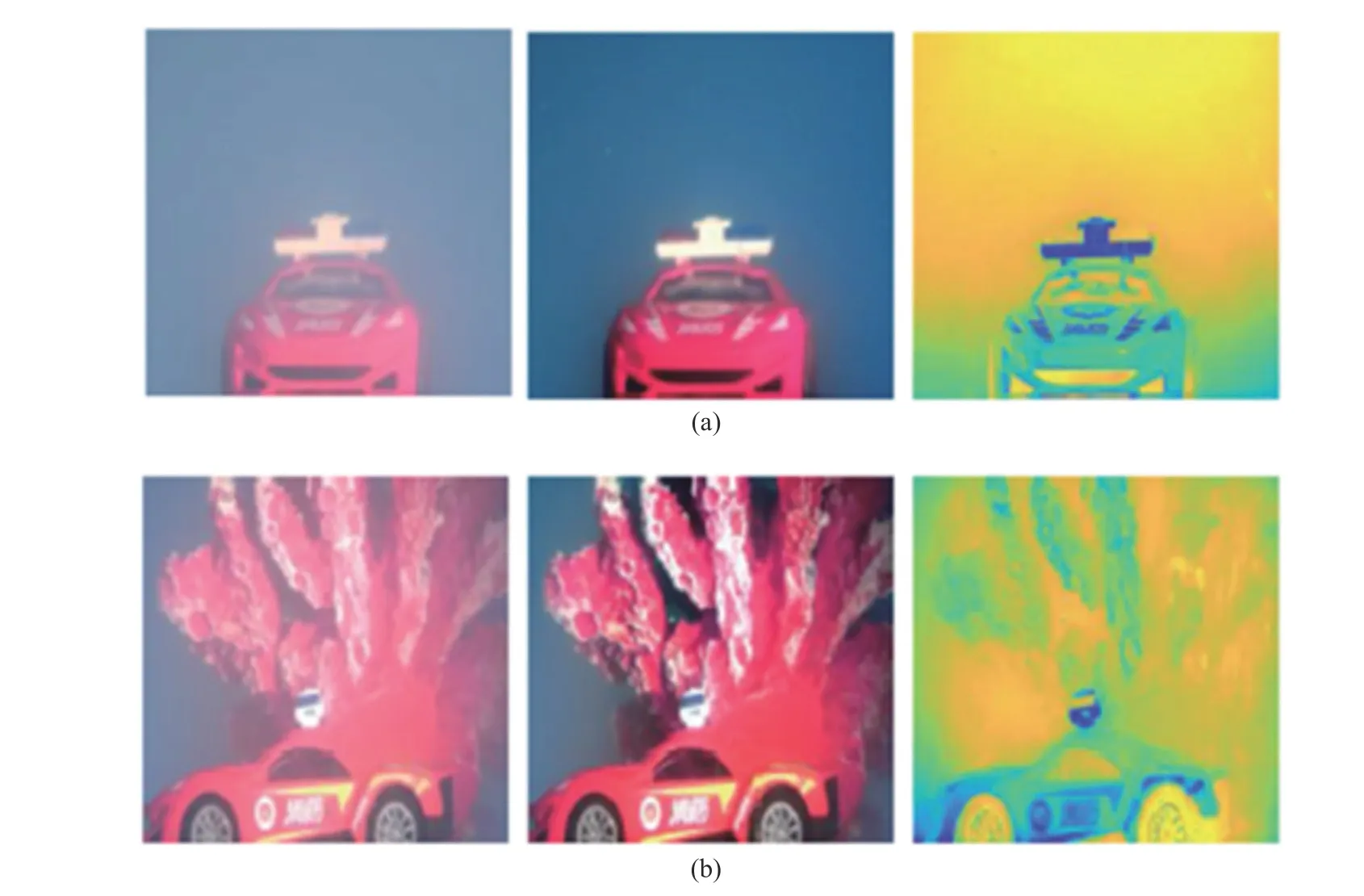
Fig. 4 The AOP maps for a scene containing multiple targets with similar colors, in which from left to right are the input images, the recovered images, and the AOP maps of the scenes: (a) the lamps on the toy car which have the same materials and different colors; (b) the overlapping part which has different materials and similar colors
However, in the AOP map, the contour of the car at the overlapping part could be distinguished. This reveals that the distribution of the AOP is not affected by color, and could distinguish targets of different materials.

Fig. 5 Experimental comparison among different underwater imaging methods under different turbidity, in which from left to right are the input image, Generalization of the Dark Channel Prior (GDCP) [8], Schechner et al. [16], Li et al. [18], CLAHE [3], Amer et al. [20] and the reported technique, the score at the top-left corner of each image refers to its IL-NIQE score, and the best result is on bold (the lower, the better)
Fig. 5 shows the restoration result of the reported technique compared with some classic underwater methods ([3, 8, 16, 18, 20]). We adopted a no-reference image quality metric IL-NIQE[21] to evaluate the algorithms quantitatively. ILNIQE is based on NIQE [22] with integrating structural statistical features, multi-scale orientation, and frequency statistics. The smaller the score is, the better the image quality will be.
As can be observed, the CLAHE [3], the method of Amer et al. [20], and The GDCP [8]algorithms perform poorly under highly turbid conditions. The method of Li et al. [18] suffers from overexposure due to the enhancement process. The recovery effect of the method of Schechner et al. [16] is close to that of the reported technique, but his method does not take into account the AOP, which is the advantage of the reported technique.
4 Conclusions
In this paper, a novel underwater polarization imaging technique is proposed, which enables the restoration of the AOP of the target. By establishing a simple and easy-to-implement experimental device, we obtained two pairs of orthogonal polarization sub-images of the underwater scene. Our strategy is to use the polarization difference between the target light and backscattered light in the two pairs of sub-images to remove the effect of backscattering. In this process, the AOP of the target is derived from the Stokes vectors. Then, we combined the non-local color priorly with the properties of light propagating underwater to estimate the transmission. We designed the experiments to validate the effectiveness of the reported technique. The experiments reveal that the reported technique has state-of-the-art performance for underwater imaging and could distinguish targets of different materials.
杂志排行
Journal of Beijing Institute of Technology的其它文章
- Objective Quantification of Small Motor Sound Quality Based on Psychoacoustic Metrics
- ISAR Imaging and Cross-Range Scaling Based on Image Rotation Correlation
- Jamming Monitoring Technology of the Space Situational Awareness Facilities:A Comprehensive Survey
- Fast Rail Defect Inspection Based on Half-Cycle Power Demodulation Method and FPGA Implementation
- Jamming Recognition Based on Feature Fusion and Convolutional Neural Network
- Unmanned Technology-Based Civil-Military Intelligent Logistics System : From Construction to Integration
