ISAR Imaging and Cross-Range Scaling Based on Image Rotation Correlation
2022-04-29FangmingLiuCongDuYujiaoDingMinghaiWangWeiDong
Fangming Liu, Cong Du, Yujiao Ding, Minghai Wang, Wei Dong
Abstract: With the rapid advancement of technology, not only do we need to acquire a clear inverse synthetic aperture radar (ISAR) image, but also the real size of the target on the imaging plane, so it’s particularly important for the ISAR to rescale the images. That is, the ISAR image which is in the range-Doppler domain is converted into the range-azimuth domain. Actually, the key point to solving the problem is to estimate the rotation parameters. In this paper, a new scheme to rescale the images is proposed. For the sake of solving the problem of two-dimensional image blur and target high-speed, the instantaneous range instantaneous Doppler (IRID) method is used to obtain ISAR images, and the rotation parameters are estimated by comparing the rotation correlation of the two images. Using this method, the error of the estimated rotation parameters is greatly reduced, so that the target can be rescaled accurately. The simulation results verify the effectiveness of the proposed algorithm.
Keywords: cross-range scaling; instantaneous range instantaneous Doppler (IRID); inverse synthetic aperture radar (ISAR); rotational correlation; rotation parameters
1 Introduction
Both inverse synthetic aperture radar (ISAR)and synthetic aperture radar (SAR) can work under any weather condition. They have superior remote sensing and high-resolution imaging capabilities, so it arouses people’s attention.Compared with SAR, ISAR plays an important role when the motion of the target is unknown,and the target is generally considered to be noncooperative [1–6]. The traditional ISAR imaging uses the range-Doppler (RD) algorithm [7–8],which performs Fourier transform on the echo data in the range and azimuth directions respectively, and a well-focused two-dimensional image can be obtained.
In order to meet the needs of practical applications, and to better extract the size and other information of the imaging target, the ISAR images are needed to be rescaled [9–11]. To rescale the image correctly, the range resolution and azimuth resolution of the ISAR image need to be known. Since the parameter information of the radar transmitted signal is known, the range resolution of the ISAR image can be calculated directly. The azimuth resolution relies on the effective rotation angle of the target which is relative to the radar line of sight during the coherent accumulation time. Therefore, the ISAR image scaling becomes a process of solving the resolution of its azimuth. However, ISAR imaging is often aimed at non-cooperative maneuvering targets, so its rotation parameters are unknown.Therefore, the ISAR images need to be rescaled by estimating the rotation parameters of the target through some methods. At present, there are many methods to rescale ISAR images of non-cooperative targets. The first type of method is based on the image quality to estimate the rotation velocity. For example, in [12], a technique for estimating the effective rotation vector modulus of the target, which uses the information carried by the chirp rate of the scattering centres,was proposed. [13] considered the degradation from target rotation, and proposed a method to estimate effective rotational velocity based on image sharpness maximization. Although this type of method has high stability, it needs to search for the best effective estimated values iteratively,which results in a lot of calculation. The second type of method is to acquire the rotational velocity by extracting the phase history of the selected prominent scatterers. The concept of optical flow was introduced in [14], and [15] proposed a method based on the extraction of the sub-pixel horizontal position of the prominent scattering centres on the range-Doppler image to estimate these rotation parameters. [16] used a way based on the synthesis of multi-dominant scatterers for the sake of estimating the chirp rate. This method is very sensitive to the sidelobes of the signal.Besides, there is also another method to estimate the rotation parameters based on the image rotation related theory. This method uses the fast Fourier transform to complete the image translation and rotation, and the calculation efficiency is high [17].
In this paper, a new method to rescale the ISAR images is proposed, which belongs to the last category of the methods mentioned above. In order to avoid the problem of two-dimensional image blur and target high-speed, this method uses instantaneous range instantaneous Doppler(IRID) algorithm to replace RD algorithm for ISAR imaging, that is, the time-frequency analysis is used to substitute traditional Fourier transform in range and azimuth domain. And for a target that rotates at a uniform velocity, the image rotation correlation algorithm is used to estimate the rotation parameters. At the same time, with respect to the non-uniform moving objects, the initial angular velocity and acceleration are obtained by the method of least squares fitting. This scheme has no restriction on the position of the scatterers, and it can significantly reduce the error of the estimated rotation parameters.
This paper is divided into the following parts: The second part introduces imaging principles and image rotation related algorithm. The ISAR imaging algorithm and the method of rotation parameters estimation are introduced in the third part. The fourth part is simulating the proposed algorithm to verify the effectiveness of this algorithm. The analysis and experimental simulation of the full text are summarized in the last part.
2 Imaging Principles and Image Rotation Related Algorithm
In an ideal situation, the target is equivalent to being placed on a turntable and rotating around the centre after motion compensation. Fig. 1 shows the geometric model.

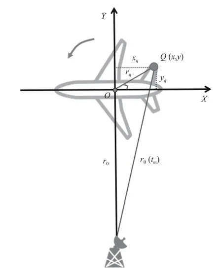
Fig. 1 Geometric model
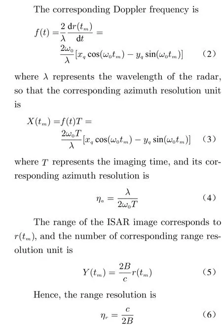

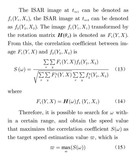
Finally, substituting the estimated target parameters into (4) and (6), scaling factors can be obtained.
3 Imaging Algorithm and Rotation Parameters Estimation
3.1 Imaging Algorithm
Different from the RD algorithm, the IRID algorithm [18] uses time-frequency analysis on each pulse echo to perform distance compression when processing the echo signal. After time sampling,the slices at the same sampling time are arranged together, and then the range profile can be obtained. Then perform motion compensation,time-frequency analysis is performed on the data of each range bin to analyze the frequency at different times, and the two-dimensional data of time-Doppler will be obtained. Consequently, the range dimension will be combined to form a timerange-Doppler image. The range-Doppler slice at each instant is the two-dimensional direction of the target corresponding to that instant. The flow chart of using IRID algorithm to process image target is shown in Fig. 2.
To confirm the effectiveness of the imaging algorithm, a target model is shown in Fig. 3. RD algorithm and IRID algorithm are used to image the target respectively, and the imaging results are shown in Fig. 4.
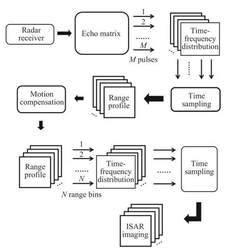
Fig. 2 IRID algorithm flow chart

Fig. 3 Target scattering points model
According to the imaging results, compared to the RD algorithm, the IRID algorithm has a significantly better imaging effect with less clutter. The Doppler value at each instantaneous scattering point is fixed, so the image will not be blurred. This method reflects the changing law of ISAR images over time, the requirements for Doppler compensation are greatly reduced. At the same time, it can also solve the blur caused by divergent scattering points.

Fig. 4 ISAR imaging results: (a) RD algorithm; (b) IRID algorithm
For an image, image entropy and average gradient are used to evaluate its quality. Image entropy shows the average amount of information in the image. For the sake of showing the spatial characteristics of the grayscale distribution of an image, we introduce a feature quantity on the basis of one-dimensional entropy which shows the spatial characteristics of the grayscale distribution. Hence, the two-dimensional entropy of the image can be obtained.

The mean gradient shows the rate of change in the contrast of the details of the image, and characterizes the relative clarity of the image. It is defined as
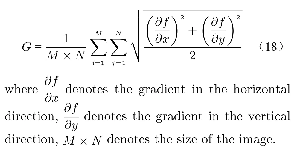
According to the definition of the image entropy and the mean gradient, it can be found that the clearer the image is, the larger the mean gradient is, the smaller its image entropy is. For the ISAR images which use RD and IRID algorithm respectively shown in Fig. 4, the image entropy and the mean gradient can be calculated on them, and the results are shown in Tab. 1.The evaluation result verifies the conclusion that IRID is a lot better than RD algorithm.

Tab. 1 Image quality comparison
3.2 Estimation of Rotation Parameters
Through the discussion above, a well-focused ISAR image is get. In order to extract target information and rescale the target better, it is rather necessary to estimate the rotation parameters.
Here, the motion state of the target is divided into two categories to discuss. One is uniform rotation, and the other is non-uniform rotation.
For the target of uniform rotation, select two groups of adjacent echoes of equal-length,and the two groups of echoes are imaged at the same time. For instance, suppose the ISAR image which is in the first group is denoted asM1at timet0, and the ISAR image which is in the second group is denoted asM2at timet0. Then select the two imagesM1andM2to perform image rotation correlation. Then the best angular velocity which is the peak of the curve is retrieved.
For the non-uniform rotation, not only must its initial angular velocity be estimated, but also its angular acceleration. Here, the image rotation related algorithm is used to acquire the rotation parameters. Fig. 5 is the specific process of this algorithm.

Fig. 5 Rotation parameter estimation


4 Experimental Simulation
Based on the above analysis, for the sake of estimating the rotation parameters of the target,the simulation data is used to be simulated.
4.1 Uniformly Rotating Target
First, a target model composed of 49 scattering points is used in Fig. 3, where the scattering intensities of all the scattering points are the same.The length of the target model is 33 m and the width is 34 m. Assume that the target rotates at an angular velocity of 0.073 1 rad/s on the turntable at a uniform speed.
The following are a series of parameter settings. The carrier frequency is 1 GHz, the bandwidth of the radar transmitting signal is 500 MHz, the pulse width is 50 μs, and the pulse repetition time is 0.02 s. Two adjacent groups of 600 pulses are selected for ISAR imaging. To ensure the accuracy of the experiment, the images at the first moment and the last moment are not to be selected. The ISAR images of the two groups of echo signals at 1.98 s are shown in Fig. 6.
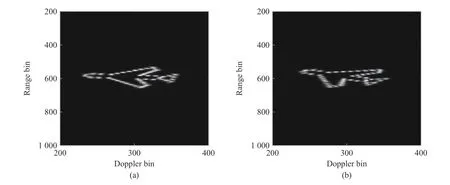
Fig. 6 The ISAR imaging results at 1.98 s: (a) the first group; (b) the second group
The imaging method used here is the IRID algorithm. Since the target rotates at a constant speed, a clear angle can be seen between the two images. To estimate the rotation parameters of the target, image rotation related algorithm is used here. According to Fig. 7, the abscissa corresponding to the peak of the curve is 0.067 63,that is to say, the rotational angular velocity estimated by this algorithm that is 0.067 63 rad/s.
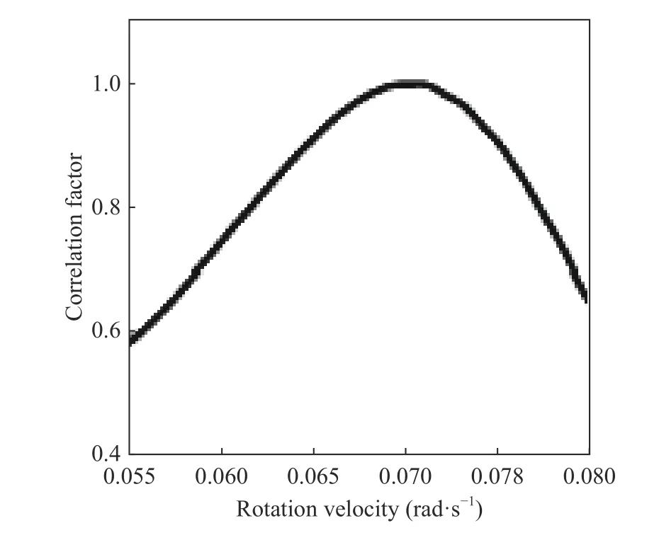
Fig. 7 Correlation coefficient curve
To prove the effectiveness of the algorithm,the RD algorithm and the image rotation related algorithm are used as a comparative experiment here. The parameter settings used are the same as the above algorithm, and the rotation speed is also set to 0.073 1 rad/s. Fig. 8 is the RD imaging of two groups of pulses. Image rotation correlation processing is performed on these two images, and the retrieved curves are shown in Fig. 9.The peak value of this curve is 0.067 51 rad/s,that is to say, when using RD and image rotation correlation algorithm to estimate rotation parameters, the error is larger than the algorithm proposed in this paper.

Fig. 8 The ISAR imaging results used RD algorithm: (a) the first group; (b) the second group
The result which uses IRID and image rotation related algorithm can be taken into (4) and(6) to obtain the scaling factor, and finally the target can be rescaled. The estimated length is 33.49 m and the width is 36.6 m. Fig. 10 shows the result.

Fig. 9 Correlation coefficient curve

Fig. 10 The ISAR image rescaled
To verify the robustness of this scheme to noise, the SNR are set to 8 dB, 10 dB and 15 dB,respectively. The rotation speeds obtained in these three cases are 0.067 51 rad/s, 0.067 52 rad/s,and 0.067 54 rad/s, respectively, and the error does not exceed 7.5%. Thus, the anti-interference ability and robustness of the system are verified.
4.2 Non-uniformly Rotating Target
The experimental result of the uniformly rotating target is introduced above, and the rotation parameters of a non-uniformly rotating target will be estimated.
Fig. 3 is also be used as the object model.For the radar transmitting signal, the carrier frequency of the signal is 1 GHz, the bandwidth is 500 MHz, the pulse width is 50 μs, and the pulse repetition time is 0.02 s. It is assumed that the target rotates at a uniform acceleration on the turntable at an initial angular velocity of 0.034 9 rad/s and an angular acceleration of 0.006 98 rad/s². Two adjacent groups of 600 pulses are selected for ISAR imaging.
The ISAR images which use IRID algorithm at 1.98 s are shown in Fig. 11. Through image rotation related processing, as shown in Fig. 12, it is estimated that the angular velocity at this moment is 0.063 92 rad/s.
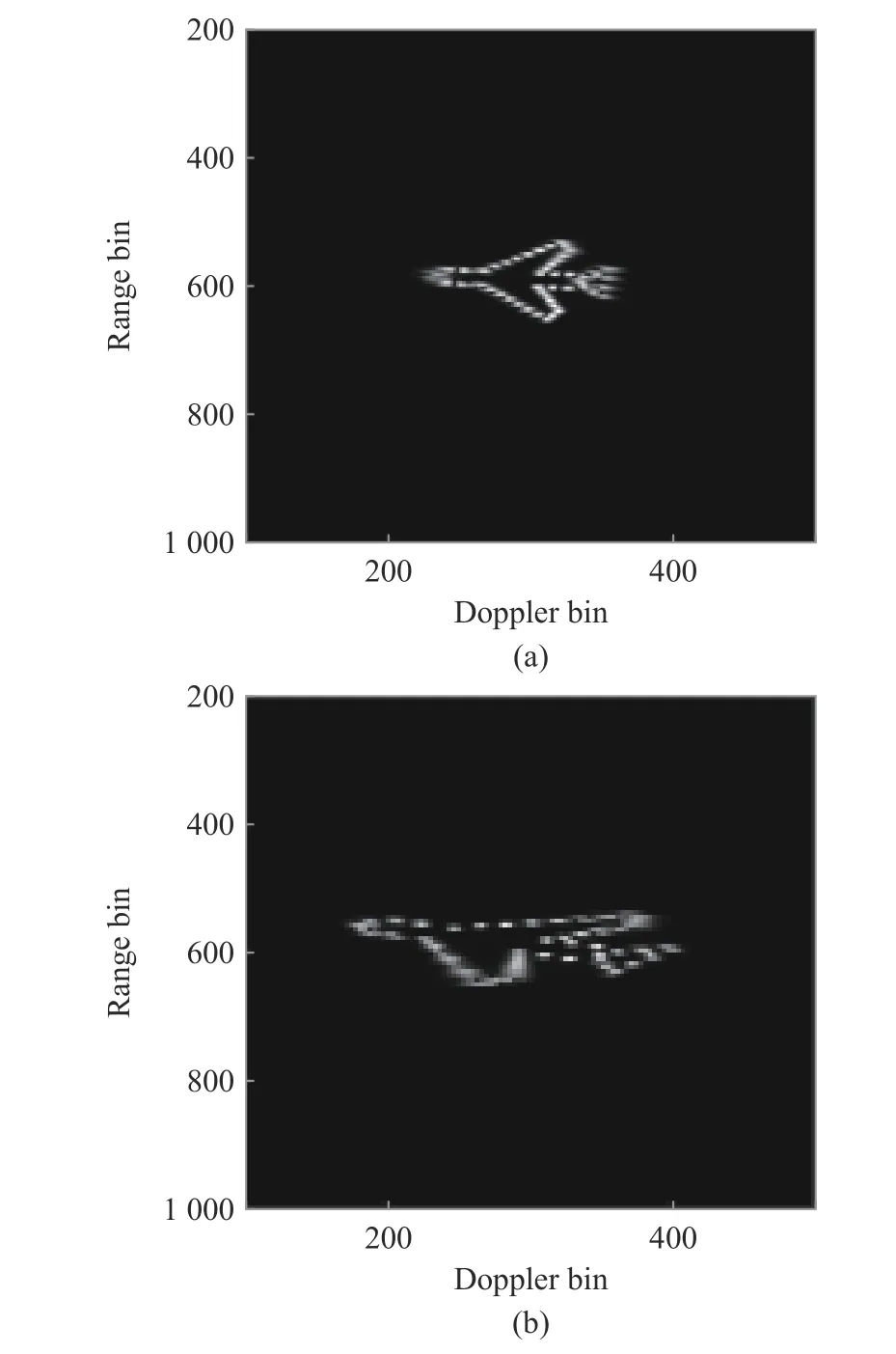
Fig. 11 The ISAR imaging results at 1.98 s: (a)the first group;(b)the second group
Here, twenty different moments are selected,after obtaining the angular velocities corresponding to different moments through image rotation correlation, as shown in Fig. 13, and the angular velocities corresponding to each moment on the coordinate axis are plotted. Thexaxis denotes time, and theyaxis denotes angular velocity.The least squares fitting method is used to fit this polyline and get a straight line, which is the black line in Fig. 13.
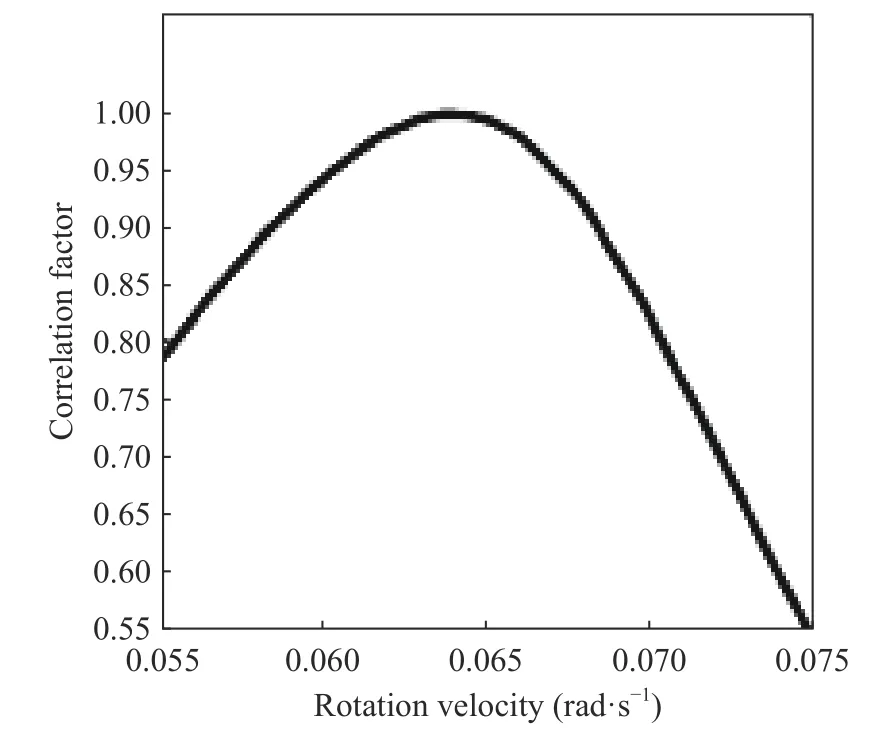
Fig. 12 Correlation coefficient curve
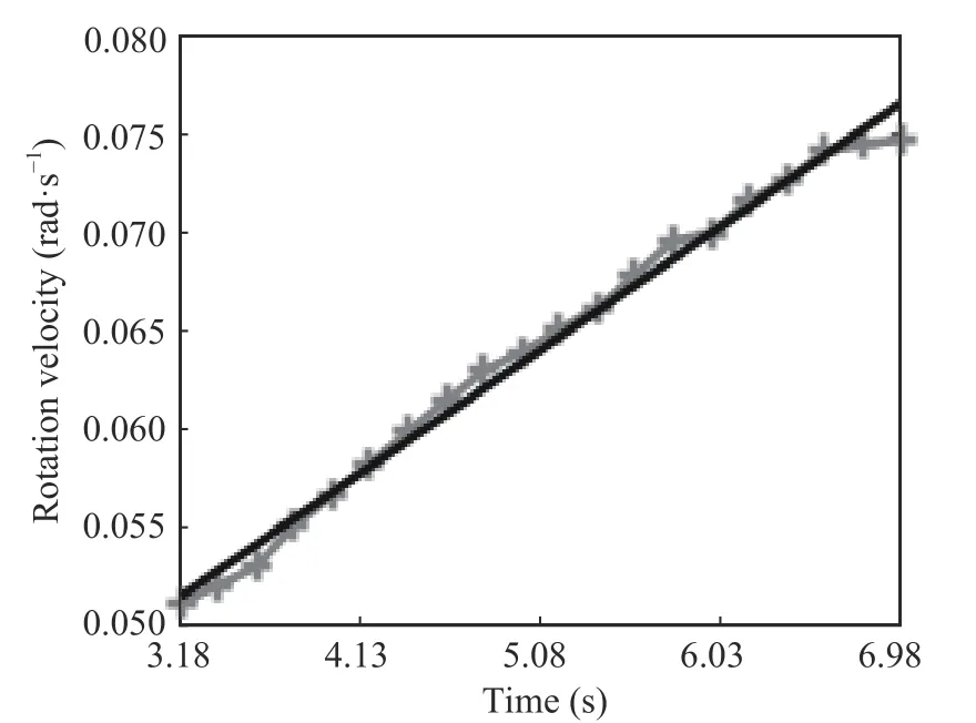
Fig. 13 The least squares fitting result
The intercept of this black line on theyaxis denotes the initial angular velocity of rotation,and the rotation acceleration is denoted as the slope of the black line, that is, the initial angular velocity of the moving target that is 0.030 4 rad/s, and the rotational acceleration that is 0.006 6 rad/s². Therefore, it can be concluded that this algorithm can well reduce the error of rotation parameters estimation, and complete the target cross-range scaling better. The estimated length and width are 36.3 m and 36.6 m, respectively.Fig. 14 is the result of the target which is rescaled.

Fig. 14 The ISAR image after cross-range scaling
4.3 Experiment on the Simulated MIG-25 Target
In this part, the MIG-25 aircraft is used to verify the effectiveness of the algorithm. Among them, the carrier frequency is 1 GHz, the radar bandwidth is 512 MHz, the pulse width is 51.2 μs,and the pulse repetition time is 0.02 s. As for the MIG-25, the length of the target is 22.3 m, and the width is 13.95 m. Suppose that the target rotates at an angular velocity of 0.078 5 rad/s and at an angular acceleration of 0.001 7 rad/s².
Similarly, as introduced above, two adjacent groups of 512 pulses are selected for ISAR imaging. Two groups of echo signals are taken at 1.18 s and 1.58 s, respectively, and the ISAR images which use IRID algorithm are shown in Fig. 15 and Fig. 16.
It can be clearly seen that the target is rotating. After processing with image rotation related algorithm, the estimated angular velocities at these two moments are 0.077 85 rad/s and 0.079 3 rad/s as shown in Fig. 17.
In this way, twenty groups of such data are used, and the final fitting result is shown in the black line in Fig. 18.
The estimated initial angular velocity and angular acceleration of the target are 0.0723 rad/s and 0.0015 rad/s². Fig. 19 shows the results of scaling derived from (4) and (6). The length of the target is about 21.96 m and the width of the target is about 13 m, which are very close to the actual size, so the algorithm can describe the actual size of the target better.
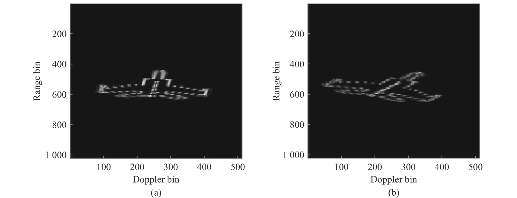
Fig. 15 The ISAR imaging results at 1.18 s: (a) the first group; (b) the second group
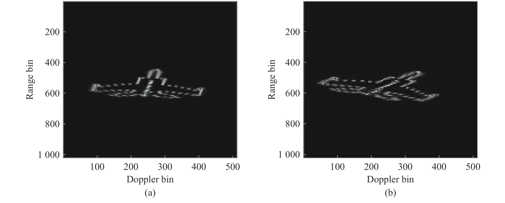
Fig. 16 The ISAR imaging results at 1.58 s: (a) the first group; (b) the second group
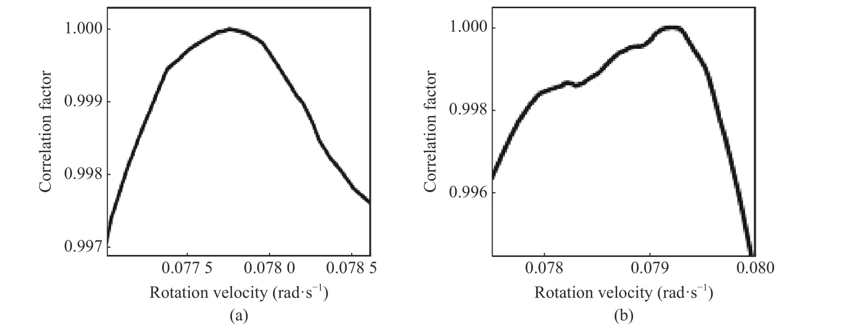
Fig. 17 Correlation coefficient curves: (a) at 1.18 s; (b) at 1.58 s
In this section, the new scheme proposed in the previous paper is simulated to verify the effectiveness of the scheme. For the ISAR image generated by the IRID algorithm, when the target rotates at a constant speed and a constant acceleration, the rotation parameters are estimated by the method of image rotation correlation transformation, and the cross-range scaling of the target is completed. This section also puts forward a comparative experiment, combining the RD algorithm with the image rotation correlation algorithm, and verifying it through simulation. It is found that this scheme can indeed reduce the error of the rotation parameter, and can better perform the cross-range scaling of the image.
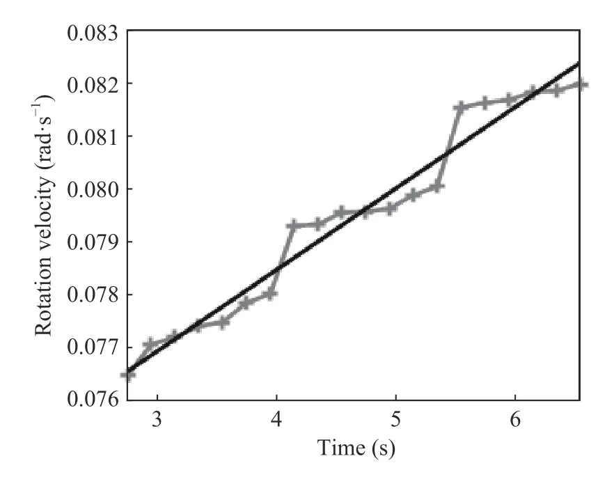
Fig. 18 The least squares fitting result

Fig. 19 The ISAR image after cross-range scaling
5 Conclusion
In order to rescale the target more accurately,this paper introduces a new algorithm. First, the IRID algorithm is used to obtain the ISAR twodimensional image, which has good focusing effect and clear imaging. Then, the image rotation correlation algorithm is used to estimate the rotation parameters of the target. Combining the IRID algorithm with the image rotation related algorithm, a clear image which is after crossrange scaling is obtained. The algorithm proved in this paper reduces the error of the estimated rotation parameters greatly, and can extract the target information better. The simulation results prove the effectiveness of the proposed algorithm.
杂志排行
Journal of Beijing Institute of Technology的其它文章
- Single-Shot 360-Degree Cranial Deformity Detection System Using Digital Image Correlation
- Unmanned Technology-Based Civil-Military Intelligent Logistics System : From Construction to Integration
- Jamming Recognition Based on Feature Fusion and Convolutional Neural Network
- Restoring Polarization Angle Map for High-Fidelity Underwater Imaging
- Fast Rail Defect Inspection Based on Half-Cycle Power Demodulation Method and FPGA Implementation
- Jamming Monitoring Technology of the Space Situational Awareness Facilities:A Comprehensive Survey
