Range of applicability of real mode superposition approximation method for seismic response calculation of non-classically damped industrial buildings
2022-04-15LiXiaodongSunHongyangJiXiaodongSanjuktaChakrabortyandWangLijun
Li Xiaodong, Sun Hongyang, Ji Xiaodong, Sanjukta Chakraborty and Wang Lijun
1. Department of Civil Engineering, Key Laboratory of Civil Engineering Safety and Durability of China Education Ministry, Tsinghua University, Beijing 100084, China
2. Central Research Institute of Building and Construction Co. Ltd, Beijing 100088, China
3. Department of Civil Engineering, Indian Institute of Technology Palakkad, Kerala 678557, India
4. Huachengboyuan Engineering Technology Group, Beijing 100052, China
Abstract: An industrial building is a non-classically damped system due to the different damping properties of the primary structure and equipment. The objective of this paper is to quantify the range of applicability of the real model superposition approximation method to the seismic response calculation of industrial buildings. The analysis using lumped mass-and-shear spring models indicates that for the equipment-to-structure frequency ratios γf > 1.1 or γf < 0.9, the non-classical damping effect is limited, and the real mode superposition approximation method provides accurate estimates. For 0.9 < γf< 1.1, the system may have a pair of closely spaced frequency modes, and the non-zero off-diagonal damping terms have a non-negligible effect on the damping ratios and mode shape vectors of these modes. For 0.9 < γf < 1.1 and the equipment-to-structure mass ratios γm < 0.07, the real mode superposition approximation method results in large errors, while the approximation method can provide an accurate estimation for 0.9 < γf <1.1 and γm > 0.07. Furthermore, extensive parametric analyses are conducted, where both steel structures and reinforced concrete structures with equipment with various damping ratios are considered. Finally, the finite element analysis of a five-story industrial building is adopted to validate the proposed range of applicability.
Keywords: non-classical damping; structure-equipment interaction; real mode superposition approximation method; complex mode superposition method; seismic response calculation
1 Introduction
The calculation of seismic response of industrial building systems should consider the dynamic equipment-structure interaction (Liet al., 1997). Often, the effect of dynamic interaction between the equipment and the primary structure is enhanced when the natural frequency of the equipment is close to that of the primary structure. Another important factor that affects the dynamic response characteristics of an industrial building system is the non-classical damping, which is developed by considering the various attributes related to the equipment housed inside the primary structure.
The time-history response analysis of a coupled structure-equipment system can provide an accurate estimate of the dynamic responses of an industrial building when subjected to ground motions. Nevertheless, the time-history response analysis is inconvenient for a regular seismic design practice since it involves complex modeling and is computationally demanding. Currently, the popular approaches used for the seismic design of industrial buildings are based on response spectrum analysis. To date, three response spectrum-based methods have been developed for evaluating seismic response of industrial buildings as follows. (1) Uncoupled method: In this method, the primary structure and equipment are analyzed separately, neglecting their dynamic interaction. In the analysis of the primary structure, the equipment is taken as an additional floor mass, while its flexibility and damping are neglected. Afterwards, the responses of the equipment are calculated based on its dynamic characteristics and the floor response spectra. (2) Real mode superposition approximation method based on a coupled model (hereinafter referred to as the “real mode approximation method”): In this method, both the primary structure and the equipment are included in a coupled model to consider their dynamic interaction. Although the damping matrix of the non-classically damped system cannot be decoupled using the undamped real mode shape vectors, the non-zero off-diagonal damping terms are neglected for simplification. The responses of the system are calculated by superposition (e.g., complete quadratic combination (CQC)) of spectrum responses of a number of real modes (Clough and Penzien, 1993). (3) Complex mode superposition method based on a coupled model (hereinafter referred to as the “complex mode method”): This method is an improvement over the previous method because it considers the nonclassical damping effect. The complex modal parameters are obtained from the eigenvalue analysis of the coupled system in the state-space domain (Yanget al., 1990), and then the seismic response of the system is obtained by superposing the spectrum responses of a number of complex modes. One promising algorithm for the complex modal response superposition is the complex complete quadratic combination (CCQC) algorithm developed by Yanget al.(1990) and Zhou and Yu (2006). Note that while other alternative methods have been proposed (e.g., Falsone and Muscolino, 2004), they are not fully mature for application in practical design.
Despite providing accurate response estimates, the complex mode method is complicated in computation, unfamiliar to engineers and not included in most commercial structural design programs. Therefore, practical engineers prefer to use the uncoupled method and the real mode approximation method. The accuracy of these two commonly-used methods is found to be related to (a) the difference in the damping ratios between the primary structure and the equipment, (b) the equipment-to-structural frequency ratio, and (c) the equipment-to-structural mass ratio (Liet al., 2018).
Table 1 summarizes the range of applicability of the uncoupled method specified in the Chinese code for seismic design of nuclear power plants (GB 50267-2019, 2019), the Chinese code for seismic design of petrochemical steel facilities (GB 50761-2012, 2012) and the U.S. standard for seismic analysis of safetyrelated nuclear structures (ASCE/SEI 4-16, 2014). As indicated in Table 1, the uncoupled method is applicable when the equipment mass is significantly lower than the primary structure mass (i.e., the equipment-to-structural mass ratioγmis very small), or the vibrations of the equipment and primary structure are not tuned (i.e., the natural vibration frequencies of the equipment and primary structure are adequately separated).

Table 1 Range of applicability of the uncoupled method specified in various codes
The range of applicability of the real mode approximation method has not yet been provided in current design codes. Nevertheless, extensive efforts have been devoted to analyzing the non-classical damping effect and estimating the error introduced by neglecting non-zero off-diagonal damping terms (e.g., Shahruz and Ma, 1988; Shahruz, 1990 and Bhaskar, 1995). Hasselman (1976) found that, for a lightly damped structure, the non-zero off-diagonal damping terms have a negligible effect on the dynamic responses, provided that adequate frequency separation exists between different modes. He proposed a criterion for neglecting non-zero off-diagonal damping terms. A similar criterion was also suggested by Warburton and Soni (1977). Shahruz and Ma (1988) and Hwang and Ma (1993) estimated the error introduced by disregarding the off-diagonal terms and proposed formulas to calculate the error bounds. Xu and Igusa (1991) revealed that for a pair of modes with closely spaced natural frequencies, the non-zero off-diagonal damping terms lead to a decrease in the modal damping ratio of one mode and an increase in the damping ratio of another mode. Consequently, for a system with closely spaced modes, neglecting the off-diagonal damping terms results in underestimation of the dynamic response. Tadinada and Gupta (2011) and Gupta and Bose (2017) estimated the significance of non-classical damping in the coupled structure-equipment systems and demonstrated that the effect of non-classical damping is significant in a tuned or nearly tuned uncoupled system for which the modes of the primary system are tuned with the modes of the secondary system.
The objective of this paper is to determine the range of applicability of the real mode approximation method for seismic response calculation of industrial buildings. The second section briefly summarizes the theory and equations of the real mode approximation method and the complex mode method. The third section analyzes the error of the real mode approximation methods using lumped mass-and-shear spring models. The error is quantified by comparison with the results of the complex mode method, and the causes and influential parameters of the error are discussed in detail. The fourth section presents the range of applicability of the real mode approximation method through extensive parametric analyses of steel and reinforced concrete (RC) primary structures with equipment with various damping ratios. Finally, finite element (FE) analysis of a fivestory industrial building is presented as a case study to validate the proposed range of applicability of the real mode approximation method.
2 Response spectrum-based methods for coupled structure-equipment systems
The equation of motion for the coupled structureequipment system when subjected to ground motion is formulated as follows:

wherex(t) denotes the displacement vectors of the system relative to the ground;(t) denotes the acceleration history of ground motion;M,CandKdenote the mass, damping and stiffness matrices of the coupled structure-equipment system;Mp,Cp, andKpdenote the mass, damping and stiffness matrices of the primary structure; andMs,Cs, andKsdenote the mass, damping and stiffness matrices of the equipment. TheUspmatrix reflect the coupling relationship between the degree of freedoms (DOF) of the primary structure and those of equipment, which contains equipment displacement vectors each of which represents the static deformation shape of the equipment system when the primary system DOF undergoes a unit displacement (Gupta and Bose, 2017).
2.1 Real mode approximation method
The natural frequencies and real mode shapes of the undamped system are obtained from the eigenvalue analysis of theMandKmatrices. Although the nonclassical damping matrixCcannot be decoupled by the real mode shape vectors of the undamped system, the non-zero off-diagonal terms of the modal damping matrix are neglected. The damping ratioζiof theith mode is calculated as:

whereωiandϕidenote the natural circular frequency and real mode shape vector of theith mode, and the superscript T denotes the transpose operation.
Based on the natural frequencyωi, damping ratioζiand associated real mode shape vectorϕi, the peak modal response of theith mode of the coupled structureequipment system can be calculated via response spectrum analysis. Afterwards, the total peak response of the system is estimated by a combination of the peak modal responses of a number of modes, based on the CQC rule as follows:

whereSkandSrdenote thekth andrth modal responses, respectively;ρkrdenotes the correlation coefficient between thekth andrth modes. More details can be found in Chopra (2007).
2.2 Complex mode method
The equation of motion (i.e., Eq. (1)) is rearranged as the following equation in state space, in which the system ofnsecond-order differential equations is reduced to a system of 2nfirst-order differential equations:

whereRandSare symmetric, real matrices of size 2nby 2n,z(t) denotes the state vector of 2nelements, of which the lowernelements represent the displacement response and the uppernelements represent the velocity response.
The characteristic value equation is then given by:

For the underdamped system withnDOFs, the solution of Eq. (7) givesnpairs of complex conjugate characteristic values andnpairs of complex conjugate characteristic vectors. Theith pair of characteristic values and the corresponding characteristic vectors are given by Eqs. (8) and (9), respectively.

whereµiis theith characteristic value;ωiandζirepresent the undamped natural circular frequency and damping ratio of theith mode, respectively; {Φi} is theith characteristic vector, of which the lowernelementsϕirepresent theith complex modal displacement vector and the uppernelements represent the associated modal velocity vectorμiϕi; andφiandψidenote the real and imaginary parts ofϕi.
For the non-classically damped system with complex modes, the displacement time history responsex(t) is expressed as a linear combination of the modal displacement responses and modal velocity responses (Zhou and Yu, 2006):

whereAiqi(t) represents theith modal displacement response,Biiq˙(t) represents theith modal velocity response,qi(t) is theith modal coordinate, and the coefficient vectorsAiandBican be determined from the complex modal properties of the system, as described in Zhouet al. (2004).
The total peak displacement response of the system can be obtained by a combination of modal spectrum responses based on the CCQC method as follows:

wherexois the total peak displacement response;ωkandωrare thekth andrth modal frequencies; three correlation coefficientscan be calculated from the natural frequencies and damping ratios of the complex modes, as described in Zhouet al.(2004);SdandSvrepresent the displacement and pseudo-velocity spectrum responses; and ◦ represents the Hadamard product operation.
Equation (11) can be further formulated as follows:

whereSarepresents the pseudo-acceleration spectra, the design form of which is specified in the design codes, and the coefficientΓkris given by:

The accuracy of the complex mode method has been validated by Yanget al.(1990) and Zhouet al.(2004).
3 Error analysis of the real mode approximation method
3.1 Single-story structure with equipment
As shown in Fig. 1, a coupled model for a singlestory structure with equipment is developed using MATLAB, where the lower mass-dashpot-spring represents the primary single-story structure and the upper mass-dashpot-spring represents the equipment. The modal analysis and seismic response analysis of the model using the real mode approximation method and complex mode method are presented below. The comparison of the results quantifies the error of the real mode approximation method, and the detailed analysis illustrates the error sources.
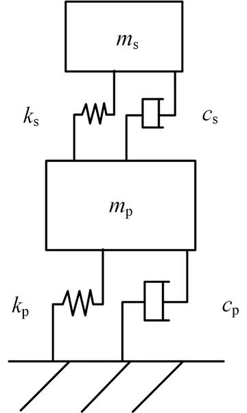
Fig. 1 Lumped model of a single-story structure with equipment system
3.1.1 Modal properties
Past studies have indicated that off-diagonal damping terms have limited influence on the dynamic responses of systems with widely spaced natural frequencies but have a significant effect on those with closely spaced natural frequencies (Hasselman, 1976; Warburton and Soni, 1977). For a coupled structure-equipment system, the spacing of its vibration frequencies is related to the equipment-to-structure frequency ratioγf=fs/fp, wherefsandfprepresent the natural frequency of the equipment and that of the primary structure, respectively. Figure 2 shows the undamped natural frequencies of complex modes for a coupled structure-equipment system, where the mass ratio ofγm=ms/mpis set as 0.1, and the damping ratio of the primary structure and that of the equipment is assumed to beζp= 0.03 andζs= 0.1, respectively. In Fig. 2, the natural frequencyωof the coupled system is normalized with the natural frequency of the primary structureωp. Note that the steel structure is assumed to have a damping ratio of 0.03 as per the Chinese code for seismic design of special structures (GB 50191-2012, 2012). The damping ratio of various types of industrial equipment ranges from 0.01 to 0.1 (ASCE/SEI 4-16, 2014), and herein, a large value of 0.1 is considered. Figure 2 indicates that when the frequency of the equipment is close to that of the primary structure (i.e.,γfranges from 0.9 to 1.1), tuning between their vibrations results in closely spaced natural frequencies of the two modes of the coupled structure-equipment system. In such a situation (hereinafter described as the formation of an “equipment-structure tuning region”), the damping interaction between two closely spaced modes is significant, and the error induced by neglecting the off-diagonal damping terms is non-negligible (Veletsos, 1986).
In the following analysis, the most critical case, i.e., a frequency ratio ofγf= 1.0 (corresponding to perfect tuning between frequencies of the equipment and primary structure), is considered for quantification of the error induced by neglecting the off-diagonal damping terms. The damping ratios remain at 0.03 and 0.1 for the primary structure and equipment respectively, while the equipment-structure mass ratioγmis taken as a variable, ranging from 0.001 to 1.0.(1) Natural frequency
Figure 3 shows the calculated undamped natural frequencies of the real modes and the undamped natural frequencies of the complex modes. The two sets of natural frequencies are similar, with an error of less than 5%. Figure 3 also indicates that the natural frequencies of the two modes increasingly separate from each other with an increased equipment-to-structure mass ratioγm, implying less interaction between the two modes at a high value ofγm.(2) Damping ratio
Figure 4 plots the damping ratios of the complex modes and the calculated damping ratios using the real modes that neglect the off-diagonal damping terms. This indicates that when the equipment-to-structure mass ratioγmis less than 0.01, neglecting the off-diagonal damping terms results in significant errors in the estimate of the modal damping ratios. The real mode approximation method estimates the damping ratio of approximately 0.065 for two modes, which obviously overestimates the damping ratio of the 1st mode while underestimates the damping ratio of the 2nd mode. This is consistent with the finding of Xu and Igusa (1991). Note that such errors in the estimated damping ratios will propagate in the subsequent analysis and lead to non-negligible errors in the seismic response determined by the real mode approximation method. When the equipmentto-structure mass ratio is greater than 0.01, the modal damping ratios calculated by both methods are similar. This is because the off-diagonal damping terms have limited influence when the natural frequencies of the two modes are obviously separated (see Fig. 3).

Fig. 2 Natural frequencies of coupled structure-equipment system (γm = 0.1, ζp = 0.03, ζs = 0.1)

Fig. 3 Undamped natural frequencies of the coupled structure- equipment system (γf = 1.0, ζp = 0.03, ζs = 0.1)
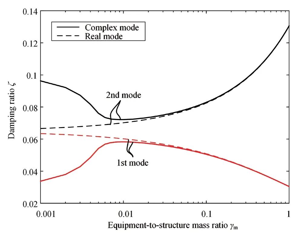
Fig. 4 Damping ratios of the coupled structure-equipment system (fs = fp, ζp = 0.03, ζs = 0.1)

Fig. 5 Mode shape vectors of the coupled structure-equipment system (fs = fp, ζp = 0.03, ζs = 0.1)

Fig. 6 Error of inter-story drift response calculated by real mode approximation method (ζp = 0.03, ζs = 0.1)
(3) Mode shape vectors
Figure 5 and Table 2 compare the real mode shape vectors with the complex mode shape vectors forγm= 0.001, 0.01, 0.1 and 1.0. When the mass ratioγmis less than 0.01, the complex mode vectors have large imaginary parts. When the mass ratio exceeds 0.01, the imaginary parts of the complex mode vectors are significantly reduced and their real parts become similar to the real mode vectors.
3.1.2 Seismic response calculation
The acceleration response spectra specified in the Chinese code for seismic design of buildings (GB 50011-2010, 2016) are adopted. The site of the industrial building has a seismic intensity of VIII, corresponding to a peak ground acceleration (PGA) of 0.2 g for the design basis earthquake (with a probability of exceedance of 10% in 50 years). The site falls into Site Class III, and the characteristic period of siteTgis 0.55 s. The damping ratio of the primary structure is assumed to be 0.03, which is the damping of steel structures specified by GB 50191-2012 (2012). The natural period of the primary structureTpis assumed to be 0.8 s. In the following analysis, the mass, stiffness and damping of the equipment are taken as variables to investigate the influence of the equipment damping, equipment-to-structure frequency ratioγfand equipment-to-structure mass ratioγm. Both the complex mode method and the real mode approximation method are used in the analysis for comparison. The error of the real mode approximation method is defined as follows.

whereSdenotes the responses (e.g., the story drift or shear force) and the subscripts “real” and “comp” represent the real mode approximation method and complex mode method, respectively.
(1) Effect of the equipment-to-structure frequency ratioγfand mass ratioγm
Figure 6 shows the errors of the estimated story drift of the primary structure by the real mode approximation method relative to the complex mode method, where the equipment-to-structure frequency ratioγfand mass ratioγmare taken as variables. Note that the damping ratio of the equipmentζsis fixed at 0.1. Relatively large errors are observed in the equipment-structure tuning region (i.e., 0.9 ≤γf≤1.1). In such a situation, the 1st and 2nd natural vibration frequencies of the coupled structureequipment system approach each other (see Fig. 2), leading to significant interaction between the two modes. For the equipment-to-structural mass ratiosγm< 0.01, the maximum error of the estimated structural drift reaches 25%, while the errors are less than 10% forγm≥ 0.1. For the equipment-to-structural frequency ratiosγf> 1.1 orγf< 0.9, the error is less than 10% despite the values of the equipment-to-structural mass ratio. If setting the error limit of 10% as criterion, the range of applicability of the real mode approximation method is as follows: (a)γf> 1.1 orγf< 0.9; or (b) 0.9 ≤γf≤ 1.1 andγm≥ 0.07.(2) Error source analysis
The error of the real mode approximation method results from the difference in the modal properties between the real mode and the complex mode, primarily on the damping ratios and mode shape vectors. Figure 4 indicates that for the mass ratioγmranging from 0.001 to 0.01, the real mode approximation method obviously overestimates the damping ratio of the 1st mode of the system while underestimates the damping ratio of the 2nd mode. Table 2 indicates that for the mass ratiosγm= 0.001 andγm= 0.01, the real part of the complex mode shape is significantly different from the real mode shape, while the imaginary part of the complex mode shape is large, which leads to the significant velocitycontribution term in the modal displacement response in Eq. (11). Figure 4 and Table 2 also indicate that the real mode approximation method provides accurate estimates of the damping ratios and mode shape vectors for mass ratiosγm> 0.1.

Table 2 Modal properties of the system (fs = fp, ζp = 0.03, ζs = 0.1)
In Fig. 7, the most critical caseγf= 1.0 is considered for comparison of the modal response of the system obtained from the real mode approximation method and the complex mode method. At a very small mass ratio, there is an obvious discrepancy in the modal response. However, the error of the 1st modal responses is less than 10% forγm> 0.04, and that of the 2nd modal response is less than 10% forγm> 0.02. Figure 8 shows the error of the combined responses of the two modes by the real mode approximation method, in the equipment-structure tuning region (e.g.,γf= 0.9, 1.0 and 1.1). The negative error indicates that the real mode approximation method leads to an underestimate of the primary structure response, and consequently may result in unsafe design.

Fig. 7 Seismic displacement response of the primary structure at different modes (fs = fp, ζp = 0.03, ζs = 0.1)

Fig. 8 Structural drift error of the real mode approximation method (ζp = 0.03, ζs = 0.1)

Fig. 9 Error of structural drift response versus equipment damping ratio (ζp = 0.03)
(3) Influence of damping ratio
Because the non-classical damping naturally originates from the difference in the damping properties between the primary structure and equipment, a larger difference in their damping ratios is expected to result in a larger non-classical damping effect of the coupled structure-equipment system. Figure 9 illustrates how the equipment damping ratio influences the accuracy of the seismic response estimation by the real mode approximation method. In this figure, the error is quantified in terms of the story drift responses of the primary structure. The damping ratio of the primary structure is fixed at 0.03, while the damping ratio of equipment varies from 0.002 to 0.1. Several cases are considered for equipment-to-structure mass ratiosγm= 0.001 and 0.1, and equipment-to-structure frequency ratiosγf= 0.9, 1.0 and 1.1. Figure 9 indicates that when the damping ratio of the equipment becomes increasingly different from that of the primary structure, the error of the real mode approximation method increases. The error is within 10%, with the exception of the cases ofγm= 0.001 andγf= 1.0. This result is consistent with the findings of Guptaet al., that for the perfectly tuned structure-equipment systems (γf= 1.0), the significance of non-classical damping increases for very slight equipment systems. In such a situation, as indicated in this figure, the real mode approximation method significantly underestimates the structural response if the equipment has a higher damping ratio than the primary structure, and overestimates the structural response if the equipment has a lower damping ratio than the primary structure.
As the variation in site class changes the design response spectrum curve, additional analysis is conducted to estimate whether site class influences the range of applicability of the real mode approximation method. Four site classes, ranging from Class I through Class IV are considered. The analysis results indicate that the site class has a very limited influence on the errors of the inter-story drift response calculation except in the cases ofγm≤ 0.007 andγf≈1.0. The aforementioned range of applicability of the real mode approximation method holds true despite the variation in the site class.
3.2 Multi-story structure with equipment
The following analysis extends from a single-story primary structure to a multi-story structure. The multi-DOF lumped mass-and-shear spring model shown in Fig. 10 is used for analysis. Similar to subsection 3.1.1, the damping ratio of the primary structure is assumed to beζp= 0.03, and that of the equipment is assumed to beζs= 0.1. The damping matrix of the primary structure is determined by superposing the damping matrices for all the modes (Chopra, 2007). For a multi-story industrial building system, the equipment-to-structure mass ratioγmand frequency ratioγfare defined as follows:

Fig. 10 Multi-DOF lumped mass-and-shear spring models

Fig. 11 Inter-story drift error versus equipment-to-structure frequency ratio γf (ζp = 0.03, ζs = 0.1)

wherefp1denotes the first undamped natural frequency of the primary structure,Mpdenotes the mass matrix of the primary structure, andMedenotes the supplemental mass matrix of the equipment, which is a diagonal matrix that is the same size asMp. If the equipment is installed in theith story, theith diagonal element ofMeis taken as this equipment massms; otherwise, it is taken as zero. In Eqs. (15) and (16), the first natural frequency and modal mass of the first mode of the primary structure are considered for the definition ofγmandγf, because the seismic response of the multi-story structure system is commonly dominated by the first mode vibration.
(1) Effect of the equipment-to-structure frequency ratioγf
A 10-story primary structure is considered. A structural mass of 500 tons is uniformly assigned for each floor, and the inter-story shear stiffness of 3.08×10⁷N/m is uniformly distributed along with the height. The first three natural vibration periods of the primary structure are 1.69 s, 0.57 s and 0.35 s, respectively. First, equipment is assumed to be located on a single floor. The mass and lateral stiffness of the equipment are taken as variables in the analysis, resulting in various equipmentto-structure mass ratios and frequency ratios. Both the real mode approximation method and the complex mode method are used for analysis, based on the design spectrum specified in Chinese code GB 50011-2010. Note that the site condition and design spectrum parameters are identical to those specified in subsection 3.1.2. The maximum inter-story drift response occurs in the first story, while the maximum error of the estimated inter-story drift (i.e., the difference in the results between the two methods, as defined in Eq. (14)) occurs at different stories depending on the mass ratioγmand the frequency ratioγf. Figure 11 shows the maximum error versus equipment-to-structure frequency ratioγffor the 10-story structure. The plots include various cases for the equipment-to-structure mass ratio (γm= 0.001, 0.01 and 0.1) and equipment location (at the 1st, 4th, 7th and 10th floors).
Figure 11 clearly indicates that the error reaches the peak value in the equipment-structure tuning region. For 0.9 ≤γf≤ 1.1, the error of the real mode approximation method is up to 25% for the small equipment case ofγm=0.01 (see Fig. 11(b)), while the error is less than 10% for the case ofγm= 0.1 (see Fig. 11(c)). Forγf< 0.9 orγf> 1.1, the error is less than 10% for various mass ratios and equipment locations, with the exception of the case ofγm= 0.01 and equipment at the first floor (the maximum error is 12%). This observation is consistent with the single-story structure results. Note that, although the error increases when the natural frequency of the equipment approaches the frequency of the second mode of the primary structure (i.e.,γf=3.0 in Fig. 11), the error remains less than 10% because the inter-story drift response is not dominated by the second mode of vibration.
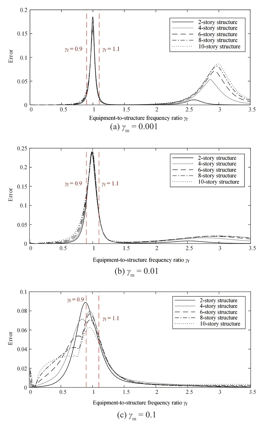
Fig. 12 Error of inter-story drift estimation for the structures of various stories (γf = 1.0, ζp = 0.03, ζs = 0.1)
To generalize the conclusions, the number of stories is taken as a variable for analysis, ranging from 2 to 10 stories. Figure 12 shows the error of the inter-story drift estimation versus the equipment-to-structure frequency ratioγffor varying stories. Note that, this figure corresponds to the case where the equipment is located on the first floor. Figure 12 indicates similar results as those described in the above paragraph. Since an industrial building is usually less than 10 stories, the observations can be generalized to most multi-story industrial buildings.
(2) Effect of the equipment-to-structure mass ratioγm
The above analysis demonstrates that in the equipment-structure tuning region (i.e., 0.9 ≤γf≤ 1.1), the non-classical damping has an increased effect and results in the inaccuracy of the real mode approximation method. The following analysis aims to quantify the influence of the equipment-to-structure mass ratio in this tuning region. The most critical equipment-to-structure mass ratioγf= 1 is considered in the analysis. An extensive parametric analysis is conducted, which includes the following variables: (a) the story number (ranging from 2 to 10); (b) the location where the equipment is installed; and (c) the equipment-to-structure mass ratio (ranging from 0.001 to 1). For each analysis case, the seismic responses are calculated using both the complex mode method and the real mode approximation method, and the errors are quantified using Eq. (14).
Figure 13 shows the errors of the maximum interstory drift calculated by the real mode approximation method. In this figure, although the plots correspond to the structures that have different stories, the results have a rather similar trend. This indicates that in the equipmentstructure tuning region, the real mode approximation method leads to an error of up to 25% at the equipmentto-mass ratioγm=0.01. As the equipment-to-mass ratio increases toγm> 0.07, the error is less than 10%. This is consistent with the conclusions obtained from the singlestory primary structure analysis in subsection 3.1. Note that although only two cases for equipment location, (i.e., at the first floor and the top floor) are shown in Fig. 13, the analysis of other equipment location cases produces the same conclusions.

Fig. 13 Inter-story drift error versus equipment-to-structure mass ratio γm (γf = 1.0, ζp = 0.03, ζs = 0.1)
(3) Equipment on multiple floors
The above analysis considers that the equipment is installed on a single floor. The following analysis considers multiple pieces of equipment installed on different floors, with the objective of generalizing the conclusions. Another extensive parametric analysis is conducted. Figure 14 shows the analysis results for one example, where four cases of equipment distribution are considered for a 10-story primary structure. The plots demonstrate how the errors of the real mode approximation method vary along with different equipment-to-structure mass ratiosγmwith the equipment-structure tuning condition ofγf= 1. Figure 14 indicates that the inter-story drift errors for the cases of equipment at multiple floors are similar to those for the case of equipment at a single story in Fig. 13. Further analysis also indicates that the range of applicability of the real mode approximation method obtained from the previous analysis (i.e., (a)γf> 1.1 orγf< 0.9; or (b) 0.9 ≤γf≤ 1.1 andγm> 0.07) holds true for the cases of equipment distributed at multiple floors.

Fig. 14 Inter-story drift error with equipment at multiple floors (ζp = 0.03, ζs = 0.1, γf = 1.0)
4 Range of applicability of the real mode approximation method for industrial structures
Section 3 proposes the range of applicability of the real mode approximation method by assuming the damping ratio of the primary structure to beζp= 0.03 and that of the equipment to beζs= 0.1. According to the Chinese code for seismic design of special structures (GB 50191-2012, 2012), the damping ratio of RC structures is taken as 0.05, and that of steel structures is taken as 0.03. In addition, the damping ratio of the equipment used in industrial buildings commonly varies from 0.01 to 0.1, as recommended by ASCE/SEI 4-16. As described in subsection 3.1.2, the variation in damping ratios for the primary structure and equipment also influences the range of applicability of the real mode approximation method. Therefore, the following numerical analysis using the lumped mass-and-shear spring models is performed to further quantify the range of applicability of this approximation method for steel and RC industrial buildings.
4.1 Steel industrial buildings
For steel industrial buildings, the damping ratio of the primary structure is assigned to beζp= 0.03, while the damping ratio of the equipmentζsis assigned from 0.01 to 0.1, with an increment of 0.01. Numerous analyses are conducted following the process described in section 3 to determine the error of the structural drift response of the real mode approximation method. Note that in the analysis, the seismic spectra are identical to those used in section 3, the height of the primary structure varies from a single story to ten stories, the equipment-to-structure frequency ratio varies from 0 to 3, and the equipment-tostructural mass ratio varies from 0.001 to 1. The limit of error of 10% is set as the criterion for the applicability of the real mode approximation method.
Table 3 summarizes the range of applicability of the real mode approximation method for steel industrial buildings. The approximation method is usable under the condition of (a)γf> 1.1 orγf< 0.9 or (b) 0.9 ≤γf≤ 1.1 andγm> 0.07 for all cases. This is identical to the conclusion of section 3. In addition, for equipment with a damping ratio close to that of the primary structure, the mass ratio limit for the real mode approximation method is further loosened. When the equipment has a damping ratio within 0.02 to 0.04, the non-classical damping effect is very limited, and the real mode approximation method can provide an accurate estimation despite the equipment-to-structure frequency ratio and equipmentto-structure mass ratio.
4.2 RC industrial buildings
A similar analysis is conducted for RC industrial buildings, except the damping ratio of the primary structure is set toζp= 0.05. The obtained range of applicability of the real mode approximation method for RC industrial buildings is summarized in Table 4. The approximation method is usable for (a)γf> 1.1 orγf< 0.9 or (b) 0.9 ≤γf≤ 1.1 andγm> 0.04. The range of applicability for concrete industrial buildings is similar to that for steel industrial buildings, except for a slight difference in the mass ratio limit in the equipment-structure tuning region. In addition, when the equipment has a damping ratio within 0.04 to 0.07, the real mode approximation method can provide accurate estimation despite the equipment-to-structure frequency ratio and equipmentto-structure mass ratio.

Table 3 Range of applicability of the real mode approximation method for steel industrial buildings

Table 4 Range of applicability of the real mode approximation method for RC industrial buildings
5 Validation by FE analysis of industrial buildings
To further validate the proposed range of applicability of the real mode approximation method, a refined FE model for a five-story industrial building was built and analyzed using the program PMSAP. The detailed three-dimensional model represents a realistic five-story prototype industrial building, including both the primary structure and various types of equipment, as shown in Fig. 15.

Fig. 15 FE model of a five-story industrial building
The primary structure adopts the braced-frame system. The beams and columns are modeled using Timoshenko beam elements, and the braces in the elevations and in the floor levels are modeled using truss elements. The beams and columns are rigidly jointed to each other, while the trusses are connected to the surrounding frames using pin connections. The storage tank is modeled using shell elements, and other equipment is modeled using beam elements and truss elements. The PMSAP can assign different damping properties to different parts. The steel primary structure is assigned a damping ratio of 0.03 for all modes of vibration, while the equipment is assigned a damping ratio of 0.1.
For simplicity, only the responses in thexdirection are presented, as the analysis in the y direction yields similar results. The first three natural vibration periods of the prototype primary structure in thexdirection are 0.60 s, 0.33 s and 0.27 s. The first natural vibration periods of various pieces of equipment in thexdirection range from 0.08 to 0.15 s. The equipment-to-structure frequency ratio calculated by Eq. (16) ranges from 4.0 to 7.5. The masses of the primary structure and equipment are summarized in Table 5. The equipment-to-structure mass ratio for the first vibration mode calculated using Eq. (15) is 0.70.
To cover a relatively wide range of equipment-tostructure mass ratios and frequency ratios for validating the proposed range of applicability, the following four cases are considered for analysis. Note that for Case 2 through Case 4, the primary structure remains identical to the prototype building, while the equipment and its stiffness and mass parameters are virtually redesigned.
Case 1: the prototype model,γf=4.0–7.5, andγm=70%.
Case 2: only heavy equipment assigned on the second floor,γf=0.99, andγm=10%.
Case 3: only light equipment assigned on the first floor,γf=3.87, andγm=0.2%.
Case 4: only light equipment assigned on the first floor,γf=1.00, andγm=0.2%.
The seismic responses of the 5-story building in thexdirection were calculated using both the real mode approximation method and the complex mode method. In the analysis, the response spectrum is identical to that used in section 3. Table 6 summarizes the errors of the responses quantified by comparison of the results from the two methods. Case 4 is beyond the proposed range of applicability of the real mode approximation method. The real mode approximation method underestimates the structural seismic responses, including the interstory drifts and story shear forces, by more than 10%. Although Case 2 falls within the equipment-structure tuning region (γf= 0.99), the equipment-to-structure mass ratioγfis greater than 7%, which thus satisfies the range of applicability. The real mode approximation method provides an accurate response estimate with an error of less than 4%. For Case 1 and Case 3, the equipmentto-structure frequency ratioγfexceeds 1.1, and the real model approximation method provides a very accurate estimation. The analysis results of the FE models of the five-story industrial building validate the proposed range of applicability for the real mode approximation method.

Table 5 Summary of the masses of the primary structure and equipment (ton)

Table 6 Errors of the inter-story drifts and story shear forces estimated by the real mode approximation method
6 Conclusions
This study presents a comparison of two spectrumbased seismic response methods (i.e., the real mode approximation method and the complex mode method) for the non-classically damped industrial buildings. From extensive analysis using the lumped mass-andshear spring models, the range of applicability of the real mode approximation method is quantified, and it is further validated by the FE analysis of a fivestory industrial building. The major conclusions are summarized as follows:
(1) When the natural frequencies of the equipment and structure are well separated (γf> 1.1 orγf< 0.9), the real mode approximation method that neglects the nonzero off-diagonal damping terms provides an accurate estimation of the seismic response of the coupled structure-equipment system, with errors less than 10%.
(2) In the equipment-structure tuning region (i.e., 0.9 ≤γf≤ 1.1), the real mode approximation method may provide an inaccurate estimate of the seismic response, particularly when the equipment-to-structure mass ratio is small. This is because in such a situation, the coupled structure-equipment system has a pair of modes with closed spaced frequencies, and the non-classical damping leads to significant damping interaction between these modes. The real mode approximation method cannot accurately estimate the damping ratios and mode shapes of these modes, and the errors of the modal properties further propagate to the seismic response calculation.
(3) For a single-story primary structure with equipment (where the damping ratios of the structure and equipment are assumed to be 0.03 and 0.10 respectively), the range of applicability of the real mode approximation method is (a)γf> 1.1 orγf< 0.9 and (b) 0.9 ≤γf≤ 1.1 andγm≥ 0.07. This range of applicability can be further extended to a multi-story primary structure if the equipment-to-structure frequency ratio and mass ratio are calculated based on the fundamental natural frequency and corresponding modal mass.
(4) For the steel and RC industrial buildings with equipment with various damping ratios, the range of applicability of the real mode approximation method is listed in Table 3 and Table 4 of this paper, which can be referenced in practical design.
(5) The analysis of a refined FE model of a fivestory industrial building validates the proposed range of applicability of the real mode approximation method for seismic response calculation.
杂志排行

Earthquake Engineering and Engineering Vibration的其它文章
- Dynamic shear modulus and damping ratio characteristics of undisturbed marine soils in the Bohai Sea, China
- Geotechnical engineering blasting: a new modal aliasing cancellation methodology of vibration signal de-noising
- Response prediction using the PC-NARX model for SDOF systems with degradation and parametric uncertainties
- Seismic behavior of multiple reinforcement, high-strength concrete columns: experimental and theoretical analysis
- Optimal design of inerter systems for the force-transmission suppression of oscillating structures
- Measurement of vibration frequencies of ties in masonry arches by means of a robotic total station