Development of hybrid optimization algorithm for structures furnished with seismic damper devices using the particle swarm optimization method and gravitational search algorithm
2022-04-15NajadAyyashandFarzadHejazi
Najad Ayyash and Farzad Hejazi
Civil Engineering, University Putra Malaysia, Seri Kembangan 43300, Malaysia
Abstract: Previous studies about optimizing earthquake structural energy dissipation systems indicated that most existing techniques employ merely one or a few parameters as design variables in the optimization process, and thereby are only applicable only to simple, single, or multiple degree-of-freedom structures. The current approaches to optimization procedures take a specific damper with its properties and observe the effect of applying time history data to the building; however, there are many different dampers and isolators that can be used. Furthermore, there is a lack of studies regarding the optimum location for various viscous and wall dampers. The main aim of this study is hybridization of the particle swarm optimization (PSO) and gravitational search algorithm (GSA) to optimize the performance of earthquake energy dissipation systems (i.e., damper devices) simultaneously with optimizing the characteristics of the structure. Four types of structural dampers device are considered in this study: (i) variable stiffness bracing (VSB) system, (ii) rubber wall damper (RWD), (iii) nonlinear conical spring bracing (NCSB) device, (iv) and multi-action stiffener (MAS) device. Since many parameters may affect the design of seismic resistant structures, this study proposes a hybrid of PSO and GSA to develop a hybrid, multi-objective optimization method to resolve the aforementioned problems. The characteristics of the above-mentioned damper devices as well as the section size for structural beams and columns are considered as variables for development of the PSO-GSA optimization algorithm to minimize structural seismic response in terms of nodal displacement (in three directions) as well as plastic hinge formation in structural members simultaneously with the weight of the structure. After that, the optimization algorithm is implemented to identify the best position of the damper device in the structural frame to have the maximum effect and minimize the seismic structure response. To examine the performance of the proposed PSO-GSA optimization method, it has been applied to a three-story reinforced structure equipped with a seismic damper device. The results revealed that the method successfully optimized the earthquake energy dissipation systems and reduced the effects of earthquakes on structures, which significantly increase the building′s stability and safety during seismic excitation. The analysis results showed a reduction in the seismic response of the structure regarding the formation of plastic hinges in structural members as well as the displacement of each story to approximately 99.63%, 60.5%, 79.13% and 57.42% for the VSB device, RWD, NCSB device, and MAS device, respectively. This shows that using the PSO-GSA optimization algorithm and optimized damper devices in the structure resulted in no structural damage due to earthquake vibration.
Keywords: hybrid optimization algorithm; structures; earthquake; seismic damper devices; particle swarm optimization method; gravitational search algorithm
1 Introduction
Damping devices have been used in high-rise buildings since the early 1970s as an effective tool to prevent severe structural damage due to earthquakes (Andrawes and DesRoches, 2007). Liet al. (2009) developed a theoretical approach to seismic ground motion by applying a transformed wavelet. The technique for the detection of instantaneous modal parameters is dependent on the continuous wavelet transformation (CWT). A novel approach using the auto-regressive moving average (ARMA) was proposed to overcome the edge effect during numerical estimation of the CWT. The results showed that the transformation of the wavelet is capable of providing profound insight into the identification of transient signals by the time-frequency maps of the time-variant spectral decomposition.
The wavelet approach is a promising and effective analytical technique for defining the dynamic parameters in both time and frequency domains. Patel and Jangid (2014) investigated the dynamic behavior of two identical adjacent structures connected with viscous dampers in two similar adjacent structures which were idealized as two-degree-of-freedom (TDOF). The viscous damper was modeled as a linear dashpot and the ground motion was assumed to occur in one direction in the symmetric planes of the structures. The objective of the study was to examine the effects of the structure′s parameters such as mass ratio and stiffness ratio on the dynamic response of coupled structures, ascertain the optimum value of the damping coefficient of the damper and derive the dynamic response of adjacent TDOF structures connected with viscous dampers. The viscous dampers were found to be effective in reducing the dynamic responses of adjacent identical structures under harmonic as well as real earthquake excitation.
Guoet al. (2017) demonstrated the real-time hybrid simulation′s capabilities. The validation study was included of damper component characterization tests and also a real-time hybrid simulation of single-degreeof-freedom systems furnished with viscoelastic-plastic dampers. The testing results demonstrated excellent agreement.
Tchamoet al. (2018) proposed a feasible alternative design technique for structures by implementing viscoelastic dampers in structure. One of the key factors employed to achieve the damper design was the interstory shear forces. Viscoelastic dampers can be designed based on 30% of inter-story shear forces which determined through the analysis under the moderate earthquake level. The proposed mothed has shown to be more costeffective and affordable, particularly when the story stiffness of the specific floors is too high in comparison to the other floors. Wanget al. (2018) proposed a design approach for viscoelastic (VE) dampers which included the use of a high-performance testing facility with a temperature control system. The damper was tested in various ambient temperatures, stimulation frequencies, and displacement amplitudes. The results of the tests showed that using the analytical model is well match with the experimental design performance of the fullscale VE damper.
Casagrandeet al. (2019) examined the feasibility of the technique for retrofitting existing structures and proposed an approach to add dampers to separate selected floor systems on a collection of multi-story frames, decoupling vulnerable nonstructural materials from the seismic source. The results indicated an improvement in structural strength and energy dissipation power, as well as a decrease in accelerations, displacements and interstory drifts, up to 43%, 41% and 40%, respectively.
Fukuda and Kurino (2019) proposed a novel semiactive oil damper to solve the shortcomings of existing oil dampers by incorporating a special energy recovery system. The damper was expressed as a four-element device consisting of a Maxwell model and a Voigt model in sequence. The results of complex loading experiments performed on a full-scale specimen and the results of simulation studies using a four-node element model showed that the system demonstrated stable efficiency and sinusoidal loading, and significantly improved energy absorption ability.
Ghorbani and Rofooei (2020) suggested a friction damper with two slip loads to regulate the seismic reaction of steel moments to avoid the construction of buildings under mild and severe earthquakes. These findings show the efficacy of the proposed double slip load dampers to effectively reduce the seismic response of the structures in terms of residual drifts, total acceleration of the surface, drifts and base shear forces relative to traditional single slip load friction dampers. Yiet al. (2019) proposed an improved sparse component analysis (SCA) procedure, fitted with a cluster estimation tool. Based on the main principle of this method, the cluster number is equal to the number of columns in the modal matrix, which is expressed in the number of rows in the scatter plot of two observations. The findings revealed that the enhanced SCA was able to detect the number of active modes for the beam and the numeric method. To increase seismographic efficiency of inelastic construction and dissipate the input energy of earthquakes, Jarrahiet al. (2020), proposed rotational friction dampers (RFD) as one of the passive control systems. The efficiency and architecture of the RFD relied on its frictional moment and the length of its stiff vertical beam. The findings showed a higher seismic efficiency in all measurements relative to the unregulated structure of the optimal RFDequipped structure subjected to historic earthquakes.
These devices provide better vibration suppression than bare structures via energy absorption at specific locations, such that the dynamic structural properties are altered, leading to improved control of the seismic responses and reduction in the energy dissipation demand of the structural members. Nevertheless, safety considerations in the design and construction of high-rise buildings due to the possibility of excessive seismic loadings are no longer the only concern. Rather, technological advances such as recently discovered lighter but stronger materials coupled with significant innovation in damping devices with the assistance of optimization procedures have offered attractive alternatives to design and construction of a better damping device configuration than previously possible. These technological achievements have given structural analysts and designers a generous scope in making a decision on different influential and response parameters, such as displacement, member force, and plastic hinge occurrence as well as the economical use of structural sections and proper placement of numerous types of damping devices, to produce the best-performing structure when subjected to earthquake loading through some selective optimization algorithms.
Within the broad spectrum of parameters mentioned above, the selection that results in the most optimized configuration is imperative. Although the chief aim in the event of structural seismic control lies in the optimization operation to minimize the severe effects of earthquake excitation, the employed procedure must consider all essential parameters simultaneously in the optimization activity. Hence, such a crucial task is best accomplished by a multi-objective optimization algorithm. Numerous multi-objective optimization methods have been proposed in the practice of mitigating seismic loads on structures. Some well-known approaches include particle swarm optimization (PSO), genetic algorithm (GA), differential evolution (DE), ant colony (AC), and gravitational search algorithm (GSA).
A synopsis of some existing works employing one or more of these methods is provided in the following paragraphs. Kargahi and Ekwueme (2009) proposed the use of the GA technique to optimize viscous dampers and built-in damper locations in existing buildings, in terms of sensitivity of probability ranges of mutation as well as crossover and population numbers on the solution. Pourzeynali and Salimi (2015) presented a practical procedure for both deterministic and probabilistic designs of an active tuned mass damper control system using the multi-objective GA to mitigate high-rise building responses. From a set of Paretooptimal solutions, reduction ratios of 70.4%, 62.6%, and 59.5% for the maximum displacement, velocity, and acceleration, respectively, were obtained. Ontiveros-Pérezet al. (2017) employed the GA approach integrated with the central finite difference computational routine to optimize friction dampers on a multi-story concrete building, using the specific mass, stiffness, Young's modulus of the material, and the damping ratio as variables, from which a reduction of more than 60% had been observed in the inter-story drift. Pathanet al. (2018) maximized the modal damping for the first three vibration modes of a double-cantilever composite structure using the constrained GA coupled with a roulette selection and the finite element methods, considering the location of viscoelastic plies, ply thickness, and stacking sequence as design variables.
Leunget al. (2008) adopted particle swarm optimization for a tuned mass damper by varying the mass ratio, damper, and damping tuning frequency for a single-degree-of-freedom system, which resulted in the minimization of the maximum displacement and meansquared acceleration. By using the bionic optimization approach, Yiet al. (2011) applied an improved GA called the generalized genetic algorithm (GGA) to find the optimal sensor locations, and to overcome the general crossover and mutation operators that may generate chromosomes that do not satisfy the constraints. Furthermore, GGA is based on recent biological theories such as the general system theory by Bertalanffy, the genetic theory by Morgan, and the punctuated equilibrium theory by Eldridge and Gould. Yiet al. (2012) developed a modified monkey algorithm (MA) to find the suitable design of structural health monitoring system sensor arrays, which was very different from the conventional method and simple to implement. The results showed that the algorithm was effective in solving combinatorial optimization problems such as optimal sensor placement. Guoet al. (2012) presented a simplified optimization strategy for nonlinear tuned mass dampers (TMD) to address the poor robustness of linear TMD, and indicated that a small perturbation of the optimal frequency ratio usually leads to a sharp decrease of the performance of the linear TMD. The standard deviation of the structural displacement was adopted as the optimized objective function. The results showed that the engineering applications of nonlinear TMDs were limited by sensitivity. Kanno (2013) presented a mixed-integer programming approach to find the optimal placement of supplemental dampers in a shear building model. The type of rounding rules that can generate good feasible discrete solutions remains unclear.
This work has fully addressed discrete optimization of damper placement in a shear building model. The proposed method can handle discrete design variables without resorting to any approximation. However, only shear building models with viscous dampers were considered. Miguelet al. (2014) proposed a robust design optimization for friction dampers to control the structural response against earthquakes. To consider uncertainties in the system, some of its parameters are modeled as random mean and variance of the maximum displacement. The results showed that the proposed method was able to reduce the mean maximum displacement to around 70% and the variance of the maximum displacement to about 99% with only three dampers. Keshtegar and Etedali (2018) introduced a new adaptive dynamic harmony search (ADHS). The optimal configuration database of tuned mass damper (TMD) parameters for the damper device under white-noise base excitation is extracted by the ADHS algorithm for the relevant engineering query. To determine the validity of a theoretical nonlinear model, a 10-story structural example subjected to earthquake excitation is considered. The findings showed that the proposed model provides an optimal tuning which is simple and reasonable. Mohebbi and Joghataie (2012) developed an optimization algorithm focused on minimization of the performance index specified as a function of the response of the nonlinear structure to be regulated. The distributed genetic algorithm was used to solve the optimization problem to determine the optimum parameters of the TMD, including its mass, stiffness and damping. The approach was applied to the configuration of a linear TMD for an 8-story nonlinear shear building with a bilinear hysteretic material activity subjected to an earthquake. The results indicated a decrease in the reaction of nonlinear structures; however, further analyses of the various geometric properties is needed. A first-order successful multi-objective optimization scheme for the design of linear viscous dampers for seismic retrofitting of frame buildings has been proposed by Puthanpurayilet al. (2020). Planned losses served as one target while the role of cost retrofitting served as another. A first-order multi-target optimization approach was followed to reach the Pareto front with a rational computational effort. The gradients of the anticipated loss function required for optimization were extracted analytically using a highly efficient approach for adjoint variables. This significantly increased the machine productivity. Li and Shu (2019) proposed the optimal placement method for metallic dampers to enhance the seismic performance of multi-story buildings. The optimization goal was constructed on the basis of costeffectiveness criteria and the optimization limit was defined on the basis of the desired seismic response level. A 16-story shear building was implemented to validate the suggested location optimization method. The findings showed that to minimize the overall cost of the dampers while maintaining the specified degree of seismic response, the objective function must be specified on the basis of the cost-effectiveness criteria rather than on the basis of the control effect or the total cost alone.
Zakianet al. (2020) developed a topology optimization formulation for shear walls to identify the stiffest construction with the best material distribution when subjected to seismic stresses and by considered of criteria such as height, primary period appearing, and opening, optimized structures display various layouts. To design structures for a number of civil, mechanical, and aerospace uses, Martin and Deierlein (2020) examined structural topology optimization. The formula called the overview of modal conformity (SMC) for dynamic topology optimization was proposed. The findings showed that the optimized topology was based on the frequency content of the earthquake. Kianiet al. (2020) suggested a finite element upgrade approach combined with a multi-objective form optimization algorithm to increase the low-cycle fatigue reaction and the energy dissipation capability of single strip slit dampers under cyclic loading. A MATLAB-based Tabu search algorithm combined with the ABAQUS/Standard finite element software package was used in the optimization process. The findings revealed that the low-cycle fatigue and energy dissipation capability of the slit dampers could be substantially improved as a result of the optimization of the multi-objective form adopted. Optimum solutions have also been used to suggest suitable shapes for construction purposes that are easy to use. Nabidet al. (2020) developed a realistic energy-dependent optimization technique for the seismic architecture of RC frame buildings with energy dissipation devices based on friction. By redistributing the slip loads of friction dampers, they were able to achieve a more consistent height-wise distribution of energy dissipation power for ideal configurations of 3, 5, 10, 15 and 20-story RC frames fitted with wall-type friction dampers under a series of synthetic spectrum-compatible earthquakes. The findings showed that the optimal design frames have up to 31 percent and 70 percent less potential inter-story drift and global impact, respectively, when compared to their conventionally designed counterparts. Abdulhadiet al. (2021) examined the damping control performance and obtained the suitable acceleration and displacement responses under severe earthquake excitation by implementing empirical mode decomposition (EMD). The results demonstrated mega sub-controlled structure system exhibited exceptional performance efficiency by decreasing reaction up to 42% and 70% for acceleration and displacement responses of top mega-frame structural and 20% and 65% for acceleration and displacement responses of sub-structure structural respectively.
Note that even though these previous studies exhibited various degrees of optimization, Changet al. (1995) and Miyamoto and Singh (2002) showed that some optimized configurations might end up with an undesirable seismic performance for the building. This is because the most popular heuristic techniques (e.g., particle swarm optimization) discussed above lack the searching ability that sweeps the entire domains of the problem (random selection), yielding solutions that were somewhat localized. Also, these methods only addressed a handful of parameters or considered optimization applicable to an idealized, simple single, or multiple degree-of-freedom systems. It has been well-corroborated that there is no single algorithm that is sufficiently general to optimize all problems (Wolpert and Macready, 1997). Two main traits are crucial for improved optimization performance, i.e., exploration and exploitation. Exploration is the aptitude of an algorithm to search entire domains of the problem space, whereas exploitation is the convergence capacity to the best solution (Mirjalili and Hashim, 2010).
Previous studies on optimizing earthquake structural energy dissipation systems indicated that most existing techniques employ merely one or only a few parameters as design variables in the optimization process, and thereby are applicable only to simple, single, or multiple degree-of-freedom structures. The current approaches to the optimization procedures have focused on a specific damper with its properties and evaluated the effect of applying time history data to the building. However, there are various types of dampers and isolators that can be implemented to enhance the seismic performance of a structure, each with different characteristics and parameters that affect the performance of the device.
Therefore, the main aim of this study is to strike an efficient balance in the capability of exploitation and exploration for a global optimum solution. For this purpose, a wedding optimization algorithm is used to unify the best exploitation trait in particle swarm optimization (PSO) with exploration in the gravitational search algorithm (GSA) to develop an improved hybrid optimization approach (PSO-GSA) for both the structural damper device and the building simultaneously. To demonstrate the ability of the proposed optimization algorithm, four damper devices, the variable stiffness bracing (VSB) system, rubber wall damper device, nonlinear conical spring bracing (NCSB) device and multi-action stiffener (MAS) device, are considered as mounted onto a three-story full-scale reinforced concrete frame structure tested by Luet al. (2008). For the optimization process, not only the parameters of the dampers system are considered, as well as details of the structural members such as section dimension and number of steel rebars. Therefore, to achieve the best optimized design, the details of the structure members are considered together with the damper properties, and are included as the multi-objective function by the PSOGSA. To demonstrate the capability of the proposed hybrid optimization algorithm, a comparative study between the bare frame and structure equipped with damper devices was carried out.
2 Structure damper devices
In this study, four types of damper devices are considered for structures subjected to the earthquake as follows:
(i) Variable stiffness bracing (VSB) system
The variable stiffness bracing (VSB) system (Patent No: US2015/0361657A1), shown in Fig. 1, comprises four nonlinear steel leaf springs that provide nonlinear and variable stiffness performance at different frame displacements. The inelastic actions of the nonlinear leaf springs in the VSB system exhibit energy dissipation characteristics and provide ductility for momentresisting frames (MRF). The VSB system is proposed to be implemented in the MRFs to dissipate energy via ductile action in the initial stage of deformation.
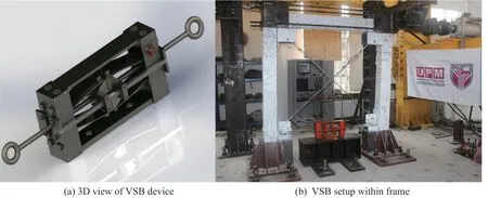
Fig. 1 Details of variable stiffness bracing device (Patent No.: US2015/0361657A1)
The VSB device performance (device force) depends on the nonlinear action of the leaf spring, which is a function of following three parameters (Fatehet al., 2015):
Le: Length of the leaf spring (mm)
W: Width of the leaf (mm)
t: Thickness of the leaf (mm)
(ii) Rubber wall damper (RWD) device
The rubber wall damper (Patent No.: US20190323254A1) is a device made of high damping rubber that is bounded with a steel plate as shown in Fig. 2. It is able to diminish structural response in terms of structural movement and plastic hinges occurred in the structural members during earthquake loading. This type of wall damper can be installed within frame structures, and can be used in both new and existing structures. The force and action of rubber wall damper is function of:

Fig. 2 Details of rubber wall damper device (Patent No.: US20190323254A1)
Cd: Damping coefficient (N.s/mm)
Ks: Shear stiffness (N/mm)
However, the damping coefficient and shear stiffness depend on the device dimensions (area of wall and rubber thickness), hardness and shear module of the rubber material, which has a wide range of values. In this study, only the damping coefficient is considered during the optimization process since both the damping and stiffness of the rubber wall damper are a function of hardness and shear module of rubber material.
(iii) Nonlinear conical spring bracing (NCSB) device
The nonlinear conical spring bracing (NCSB) system (Patent No.: PI2015703892), shown in Fig. 3, can be used as a nonlinear lateral resistance component in framed structures. The NCSB device consists of two solid telescopic conical springs attached to steel wire ropes. The application of the NCSB in framed structures, particularly in a moment-resisting steel frame (MRSF), improves the seismic response of the frame due to its nonlinear action.

Fig. 3 Components and body of nonlinear conical stiffness bracing device (Patent No.: PI2015703892)
The force of the NCSB is a function of the device parameters described as follows (Fatehet al., 2016):
LeNCSB: Length of the spring (mm)
Dia: Largest diameter of the spring (mm)
dia: Smallest diameter of the spring (mm)
nD: Diameter of conical spring (mm)
CN: Numbers of coils
(iv) Multi-action stiffener (MAS) device
The multi-action stiffener (MAS) device, shown in Fig. 4, consists of a combination of three springs of different lengths placed in parallel to demonstrate three levels of stiffness depending on the applied displacement. Therefore, the vibration is effectively reduced by the increase of displacement. In other words, due to the small stiffness of the system at the first stage, the device does not function with a full capacity, which leads to the structure having enough ductility.

Fig. 4 Schematic body of MAS
However, by increasing the displacement, the performance of the device is increases and it generates more stiffness, which reduces the effect of vibration in the structure. Two steel shafts (solid and hollow) are placed in the middle of the device. The hollow shaft can move with the spring movement to provide the stiffness, but the solid shaft is utilized as the center of the springs during earthquake loading.
The following parameters are the main characteristics that affect to performance of the MAS device (device force).
WDsp1: Wire diameter for Spring 1 (mm)
ODsp1: Outer diameter for Spring 1 (mm)
CNsp1: Number of coils for Spring 1
WDsp2: Wire diameter for Spring 2 (mm)
CNsp2: Number of coils for Spring 2
WDsp3: wire diameter for Spring 3 (mm)
CNsp3: Number of coils for Spring 3
The wire diameter of Spring 1 is larger than the wire diameter for Spring 2 and Spring 3. In addition, the wire diameter for Spring 2 is larger than Spring 3 since all three springs are nested in parallel. Spring 1 is the outer spring, Spring 2 is in middle and Spring 3 is positioned in the core shown in Fig. 4. Based on the design of the MAS device, each spring starts the function in a specific displacement stage as illustrated in the following:
Dsp1: Displacement functioning stage for Spring 1 (mm)
Dsp2: Displacement functioning stage for Spring 2 (mm)
Dsp3: Displacement functioning stage for Spring 3 (mm)
Therefore, the force of the device is consistent with the action of each of the springs, which function in parallel.
Then, all the parameters described above are considered as the main characteristics of the MAS device during the optimization process.
3 Development of PSO-GSA multi-objective optimization method
In this study, a multi-objective optimization algorithm is developed for a structure furnished with any of the four vibration dissipation devices described in the previous section.
The optimization procedure is applied in two steps; the first is to find the optimum parameters for the vibration dissipation devices and reduce the weight of the building (section sizes), and the second is to find the optimum location of the device in the structure frame.
Therefore, the main aim of this study is to develop a multi-objective optimization method by hybridization of the PSO-GSA to optimize structures equipped with vibration dissipation devices to minimize their seismic load effects.
Linking the MATLAB software to the ARCS3D (the structural analysis program) program is necessary to read the input file provided by the ARCS3D program and edit the file. Furthermore, after executing the optimization process, the file is again resent to the ARCS3D program and this process is repeated throughout the entire optimization process for hundreds to thousands of times to achieve the optimum set.
Since the input file is composed of many overlapping matrixes, writing and reading the input file is a challenging issue. To overcome this problem, at the first step, the input file is searched and opened and the content is interpreted as matrix characters. Moreover, a number is assigned to each data line in the input file for reading, writing and collecting the data.
The second step separates each part of the matrix and gives each part a title to recognize it. Each part is coded to change it from a character matrix to a number matrix, so that it will be editable and the optimization process can then be executed.
The third step is to collect all the data (result of optimization) after the optimization process such as the fitness function, parameter of the devices for each iteration, plastic hinges and displacement, etc.
The step-by-step procedure for three-dimensional (3D) analysis of buildings with a supplementary vibration damper device is outlined as follows:
Step 1:Select the appropriate vibrational damper devices (various damper types) to be implemented in the structure and define the damper characteristics to be optimized for the selected damper devices as shown in Section 2 (i, ii, iii, iv).
Step 2:Define a range of limits (lower and upper limit) for each of the parameters to obtain the parameters within the defined range during the optimization process. All the variables in each generation should be within the defined limit. The upper and lower limits are defined as vectors as shown in Section 3.4.
Step 3:Develop the initial finite element model of the considered structure in the ARCS3D program and link (connect) the finite element program to the optimization computation platform (MATLAB Software) through the API documentation of ARCS3D as shown in Sections 3 and 3.1.
Step 4:Determine the objective function and penalty function and apply constraints to the objective function as shown in Sections 3.2 and 3.3.
Step 5:Conduct the optimization process for the considered structure with the selected damper devices and perform a time history analysis by implementing the appropriate earthquake record as shown in Section 4.
Step 6:Obtain the optimum design for the structure furnished with the best damper devices by minimizing the objective function, which consists of the weight of the structure and its seismic response (nodal displacement and plastic hinges occurrence in structural members).
3.1 PSO-GSA optimization algorithm
The computational description of the proposed particle swarm optimization and gravitational search algorithm (PSO-GSA) is outlined in a flowchart illustrated in Fig. 6 and outlined below.

Fig. 5 Integrated synchronized computation system to connect MATLAB to ARCS3D
First, the initial population is generated for all agents, which consists of:
(a) Parameters of the structure:
The dimension of the column and beams, the number of reinforcement and diameter of the reinforcement, and the location of the devices are randomly initialized.
(b) Parameters of the damper devices:
(i) VSB device: The length of the leaf spring (Le), width of the leaf (w) and thickness of the leaf (t)
(ii) RWD device: Damping coefficient
(iii) NCSB device: The length of the spring (LeNCSB), the largest diameter of the spring (Dia), the smallest diameter of the spring (dia), the diameter of conical spring (nD) and the number of coils (CN)
(iv) MAS device: Wire diameters, outer diameters, number of coils and displacement functioning stage for all Spring 1, Spring 2 and Spring 3.
Each agent is considered as a candidate solution. Thus, for each parameter, a random variable is assumed to be in the upper and lower limit that was already set.
Secondly, after the initialization, resultant forces among agents, the gravitational force and constant are calculated using the following equation:

whereG0is the initial gravitational constant,αis the descending coefficient, iter is the current iteration, andmaxiteris the maximum number of iterations.
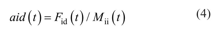
Thirdly, in a problem space with the dimensiond, the total force that acts on agentiis calculated using the following equation:

whereFijdthe gravitational forces and randjis a random number in the interval [0,1]. The accelerations of particles are defined as
wheretindicates a specific time,dspecifies the dimension of the problem, andMiindicates the mass of objecti. It is important to note that in each iteration, the best solution outcome (gbest) for each repetition should be updated.
Next, subsequent to calculating the accelerations and updating the best solution so far, the velocities of all agents is calculated using the following equation:

whereVi(t) is the velocity of agentiat iterationt;cjis an acceleration coefficient,wis a weighting function, rand is a random number between 0 and 1,aci(t) is the acceleration of agentiat iterationt, andgbestis the best solution so far. Finally, the positions of the agents are updated by:

The process of updating velocities and positions is stopped by meeting the end criterion. The considered parameters of PSO-GSA have proven to be very efficient in reaching the optimum solution based on prior work by Mirjaliliet al. (2012), where it was applied to train feed forward neural networks. Also, Razmjooy and Ramezani (2016) applied these parameters for system identification. Therefore, in the present study, a few parameters are tried; however, the analysis results indicated that the parameters that were proposed in prior studies led to better optimization results. These parameters are as follows:
Population size=30,c1=1,c2=1,w=random number in [0,1],G0=1,α=20, maximum iteration=1000, and stopping criteria=maximum iteration.
3.2 PSO-GSA optimization objective function
The objective function (fobj), for the developed PSOGSA optimization process is defined as a function of all three-dimensional movements of the structure for three points plus the sum area of the columns and beams (ΔX, ΔY, ΔZ,AC,AB).
Inelastic time history analyses are performed to evaluate the response of the structure during earthquake excitation. To assess the critical condition, peak displacements (positive and negative) are used to determine the objective functions. For simplicity, the positive peak displacement is called the maximum displacement, and the negative peak displacement is called the minimum displacement.
This study considers a three-dimensional structural model with multidirectional support excitation. To consider the effect of the weight of the structure and the effects of displacements in all directions in the optimization process, the following equations are proposed:
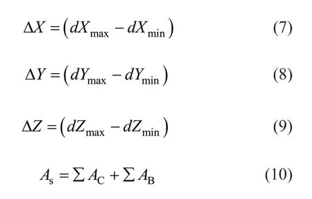
wheredmaxanddminare the peak minimum and peak maximum of the time history displacements in theX,Y, andZdirections. Also, ΔX, ΔY, and ΔZare the net displacement in theX,Y, andZdirections, respectively.
ACis the area of the columns andABis the area of the beams, andAsis the total area of the structure. These values are determined for each point in each story level.
The displacements in each direction are in a different range and independently affect the optimization process, therefore to scale the displacements, the moderation coefficients ofØx,ØyandØzare used to multiply the displacements in each direction so that they are all scaled within the same range.
Similarly, a moderation coefficient ofØAsis multiplied to the sum area of the beams and columns to scale the value and then both the displacements and area values have an equal impact on the objective function.
Thus, the objective function is proposed as follow:

Equation (11) is proposed to find the optimum weight of the building and optimum parameters for the damper′s devices and Eq. (12) is proposed to find the optimum location for the devices as:

3.3 PSO-GSA optimization design constraints
The design constraints are used to restrict the damage (plastic hinge formation) in the structural members since the hybrid optimization is based on unconstrained functions.
Therefore, research considered the total number of plastic hinges occurring during the loading and unloading of the structure members during earthquake excitation as optimization constraints. Thus, the penalty function is defined as

wherepis the penalty function, andPHirepresents the design constraints, which are the total number of plastic hinges that occur in structural members. In this equation,CPHirepresents the adjusting coefficient for constraints, and it has a large value to avoid the occurrence of plastic hinges.
The penalty function restrains the genetic algorithm in terms of the plastic hinge occurrences and the ineligible displacements simultaneously. The supplemental function is obtained by adding the penalty function to the objective function as follows:

whereФis the competency function or the equivalent free function.
Therefore, during the optimization process, the hybrid optimization tries to avoid plastic hinge occurrences in the structural members as an optimization constraint and minimize structure movements in three directions for all stories as the main objective of the optimization.
3.4 PSO-GSA optimization design parameters
The governing equation of motion for a structure furnished with vibration dissipation devices is:

where:
M: Mass of the structure
C: Inherent damping of the structure
K: Stiffness of the structure
Fe(t): Earthquake force as the external force
Fdevice: Force of the vibration dissipation device
X,X,X: Acceleration, velocity and displacement, respectively
Depending on the device type, the force can be a function of either velocity or displacement or both:
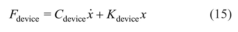
Therefore, all device parameters that have an effect on the force of the vibration dissipation dampers are considered as the optimization design parameters to find the most effective force of the device to minimize the seismic response of the structure. Moreover, for beams and columns, a predefined amount of 20 sections has been considered and each section was defined in the optimization as a natural number However, the diameter and number of reinforcements are defined initially, and all are changed depending on the outlined objective function. Furthermore, for the damper devices, the upper and lower limits are defined based on the available range of the device and its characteristics with some constraints for some dampers, since some of the values should not exceeds the others. Then, during the optimization process, these values are selected randomly and based on the objective function in each iteration, the search changes within the predefined range to explore all the possibilities to find the optimum set.
The range of the limit for each parameter must be defined to select a value within this range during the optimization process. Therefore, all the generated variables in each generation should be within this limit. The input of the upper and lower limit is defined as a vector:
Upper-limit = [U1,U2, …,Un]
Lower-limit = [L1,L2, …,Ln]
Tables 1 to 5 list the upper and lower limits of the parameters for the structure as well as for each of the four considered devices:
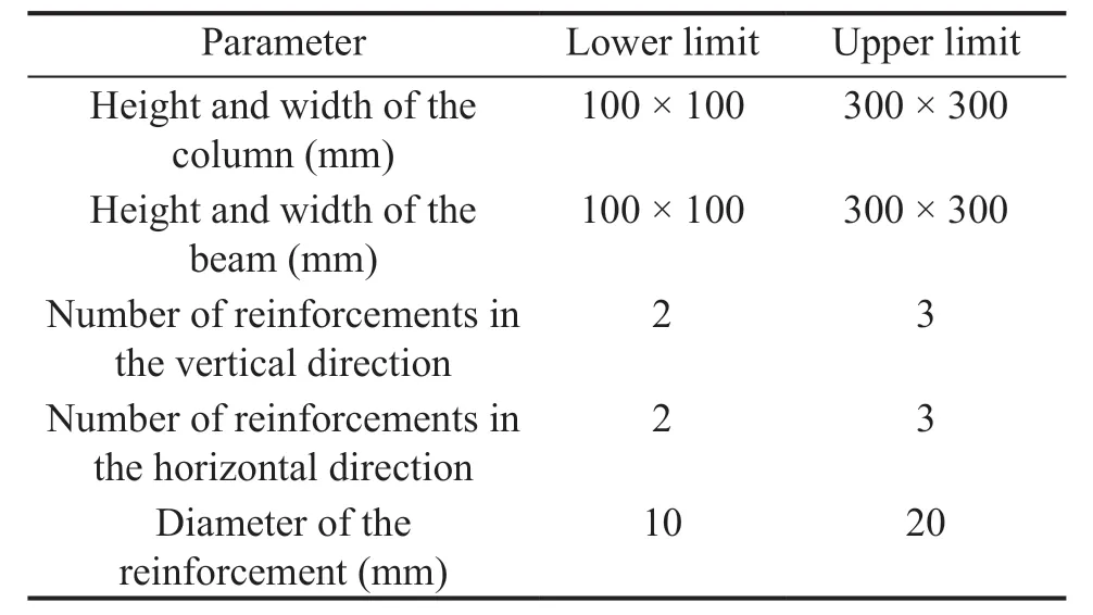
Table 1 Upper and lower limit for the characteristics of the structure

Table 2 Upper and lower limit for the VSB device

Table 3 Upper and lower limit for the rubber wall damper device

Table 4 Upper and lower limit for the NCSB device
4 Application of PSO-GSA optimization to three-story reinforced concrete frame- building
The proposed optimization algorithm is applied to a three-story reinforced frame studied and tested by Luet al. (2008) using a shaking table. The geometrical and mechanical properties of the frame are given in Fig. 8 and Table 6, respectively. however, the beams located along theZaxis (see Fig. 7) where the devices are installed, have different sizes (Fig. 8(c)), furthermore, the same for columns as the columns connected to the devices have different section properties from the corner columns as shown in Figs. 8(a) and 8(d). The rebar in the middle columns are (4ϕ14 for the corner, 2ϕ12 in the middle), 4ϕ14 for the corner columns , 4ϕ14 for the beam section and 4ϕ12 for the beam section connected to the devices, and the concrete cover is 20 mm. Figure 9 illustrates the El-Centro earthquake excitation (1940).

Table 6 Mechanical properties of concrete and steel
5 Validation
To verify the proposed finite element model, time history analysis was conducted for the considered three-story RC structure and the maximum horizontal displacements were attained and compared with the experimental test results for the same three-story RC structure using the shaking table, as reported by Luet al. (2008).
Figure 11(a) shows the peak displacements obtained from the experimental results by Luet al. (2008) and Fig. 11(b) shows the horizontal displacement from the numerical analysis made via the present work.
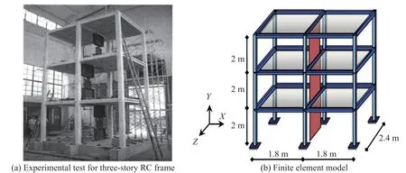
Fig. 7 Three-story RC frame (Lu et al., 2008)
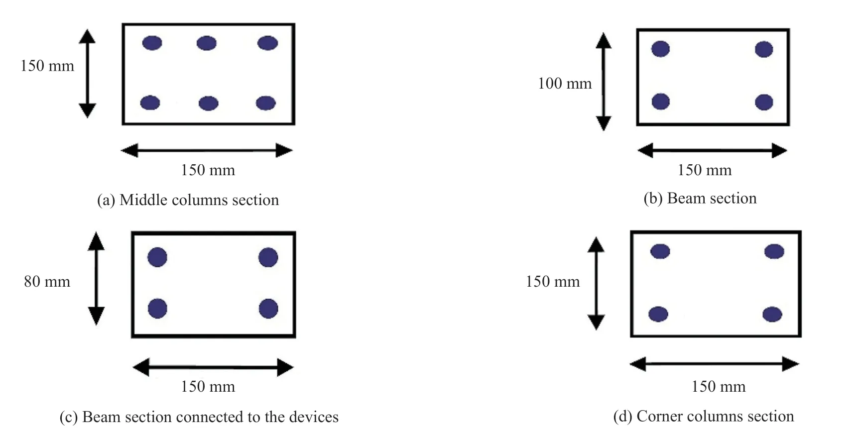
Fig. 8 Structural cross-section; (a) middle columns section; (b) beam section; (c) beam section connected to the devices; (d) corner columns section
The maximum displacement for the second and third floor that resulted from time history analysis by ACRS3D was 9.26 mm and 12.1 mm, respectively, and the peak displacement measured by Lu during experimental testing on shaking table was 10.06 mm and 12.6 mm for the same corresponding points. Therefore, comparison of the values and graphs indicates that the result of the analysis using the analytical model developed for this study is in very close agreement with results of the experimental study by Lu. Thus, the analytical model developed through the ARCS3D finite element program is demonstrated and proven reliable.
6 Results and discussion
The result of the optimization process for a structure furnished with any of four devices are discussed in this section. The seismic response of the structure is assessed, and the total numbers of plastic hinges at each floor level are rerecorded during the optimization process. The discussion focuses on the optimization of the structure and the device parameters, followed by the optimization of the location of the devices in a three-story reinforced structure.
6.1 Optimization of seismic effect on structure and structure weight
The total number of plastic hinges that occurred throughout the unloading and loading of the structural members due to vibration during the optimization process is shown in Fig. 12. The total amount of plastic hinges developed in the structure is reduced from 41, 13, 12, and 46 in the first iteration to 0 at 664, 860, 720, and 550 iterations of the optimization process for the VSB device, rubber wall damper, NCSB device and MAS device, respectively. This shows a 100% decrease in the total number of plastic hinges in the structural members and indicates that the developed PSO-GSA algorithm was successfully able to optimize the structure and damper device details to prevent any damage to the structural members and protect the building against imposed seismic excitation.
Furthermore, the minimization of the objective function is shown in Fig. 13. The overall section area of the columns and beams of the structure is reduced from 0.66 m2in structure furnished with any of the four devices to 0.468 m2at the final iteration. This is a 29.1% deduction in the total section areas, which led to a reduction in the total weight of the structure from 3.275 t to 2.57 t. Therefore, implementing the vibration dissipation device in the considered three-story structure resulted in reducing the total weight of structure by 21.53%, which significantly decreases the cost of materials and construction.
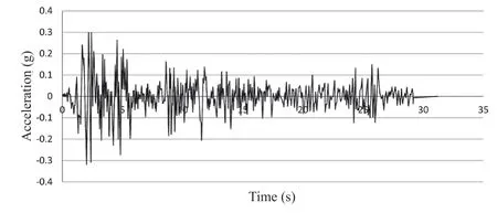
Fig. 9 Earthquake record of the north-south component of the El Centro earthquake (USA, 1940)
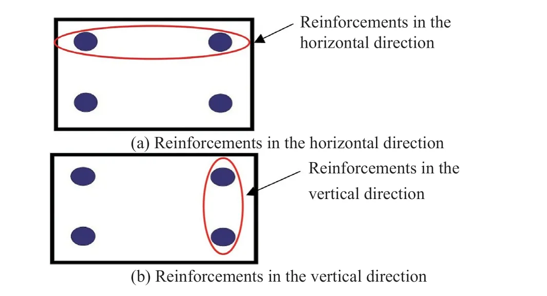
Fig. 10 Reinforcement layout in the vertical (3-3 axis) and horizontal (2-2 axis) directions
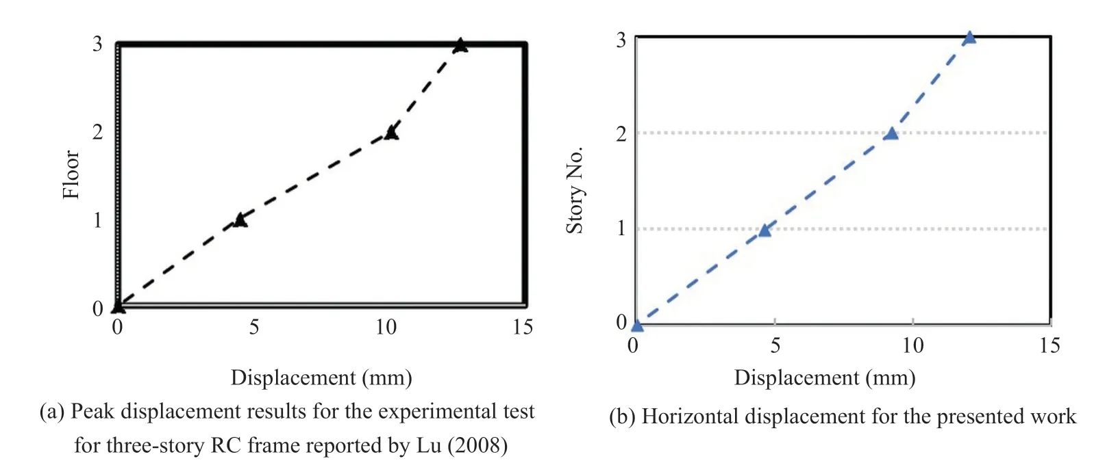
Fig. 11 Validation result of the horizontal displacement
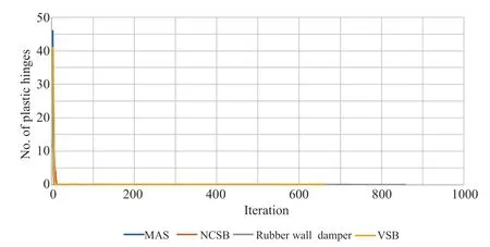
Fig. 12 Comparison of number of plastic hinges between the devices

Fig. 13 Comparison of objective function between the devices

Fig. 14 Position of VSB device in the three-story RC frame structure

Fig. 15 Position of RWD device in the three-story RC frame structure
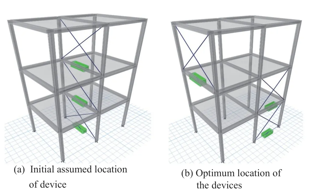
Fig. 16 Position of NCSB device in the three-story RC frame structure
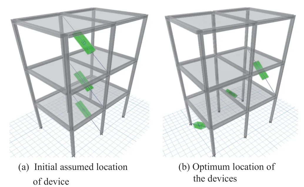
Fig. 17 Position of MAS device in the three-story RC frame structure
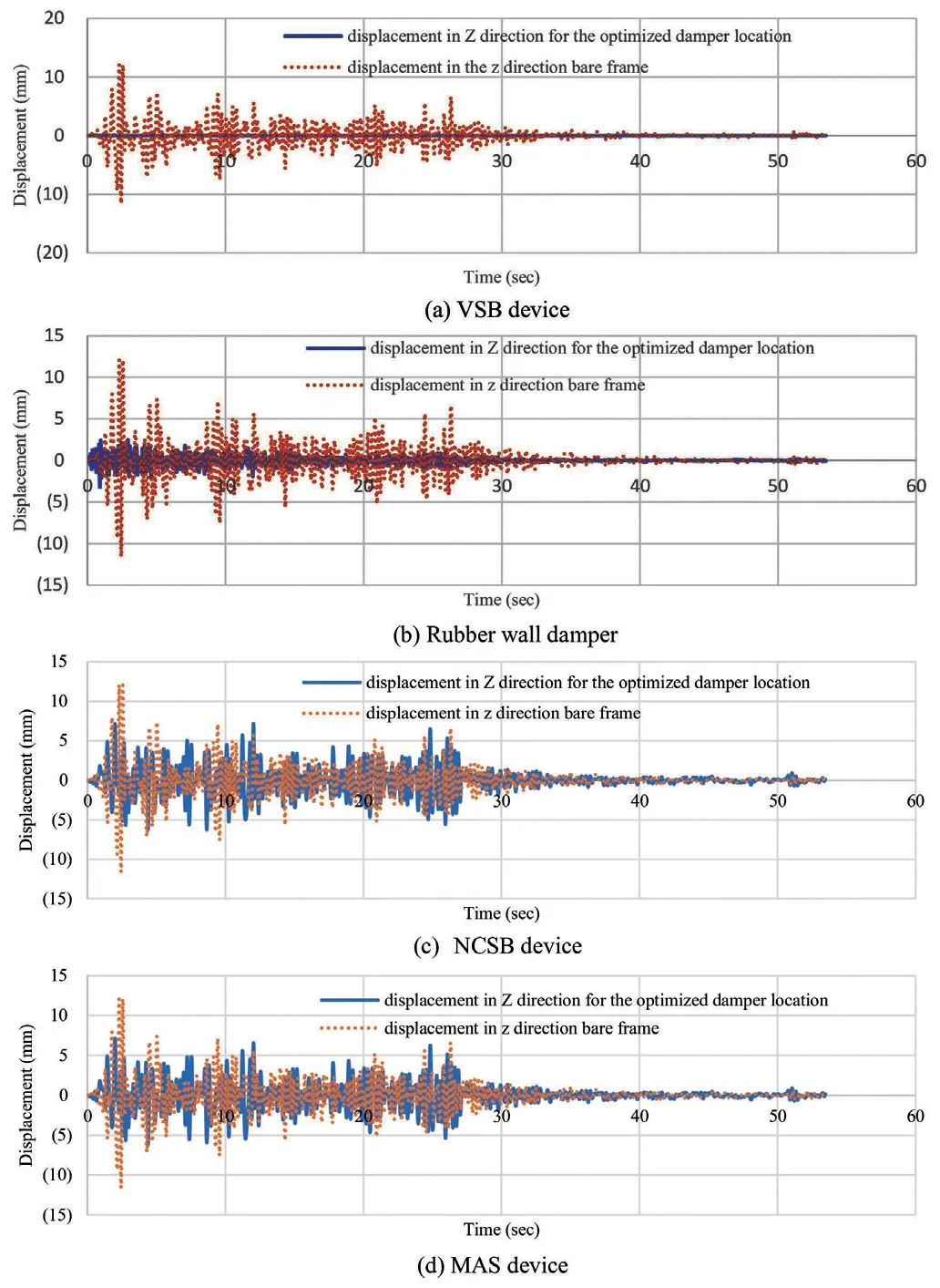
Fig. 18 Time history displacement in the z-direction for bare frame and frame furnished with device

Fig. 19 Time history displacement in the x-direction for bare frame and frame furnished with device

Fig. 20 Objective function of the location
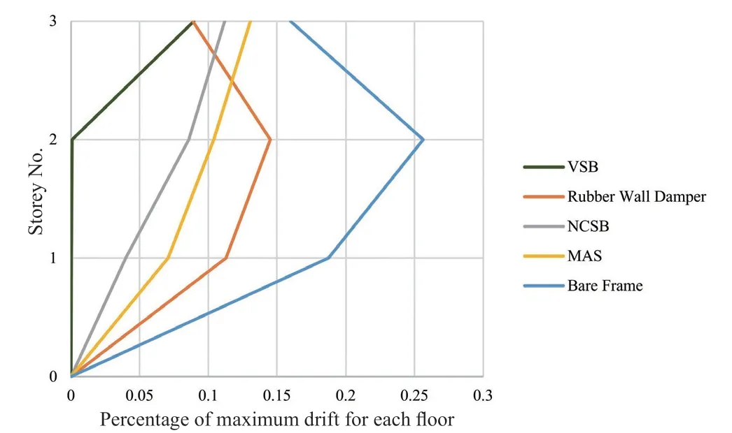
Fig. 21 Percentage of maximum drift for each floor (%)
Furthermore, it can be observed that the VSB device and MAS device has a greater effect on the functionality of the devices as the stiffness changes dramatically with the variation of the parameter. Thus, the number of plastic hinges is higher when compared with the rubber wall damper and NCSB device.
6.2 Optimization of device location based on time history analysis
The initial considered position of the device in the frame and optimized location of the devices in the frame were determined using the proposed PSO-GSA algorithm are shown in Figs.14–17 for the VSB device, rubber wall damper, NCSB device, and MAS device, respectively.
As can be seen in the figures, there is no similar pattern of positioning of the device within the frame for any of the considered devices. This may be due to different performance and action of each device for dissipating vibration.
The VSB and NCSB devices are connected to the two opposite beam - column joints in a frame using steel wire; however, the MAS device is implemented in one joint only to diminish horizontal movement. The RWD is installed within the frame and connected to beams in the upper and lower floors to diminish inter-story movement. Therefore, each of the devices has different characteristics and actions which cause a different load transfer mechanism in the structure. Therefore, it is not surprising that the optimum positions of each device are different.
The horizontal time history displacement responses in thezandxdirections for the upper floor are shown in Figs.18 and 19, respectively, for the optimized location of each device.
The peak displacements resulting from the time history analysis of the structure with the considered damper devices are depicted in Tables 8 and 9. As can be seen throughout the results, implementing the optimum device in the determined positions by the optimization algorithm effectively reduces structure nodal movement during the applied earthquake excitation.
As listed in Table 8, the reductions for the peak maximum displacement in thez-direction is in range of 99.9%, 77.54%, 40.43% and 40.51% for the structure equipped with VSB, RWD, NCSB and MAS device respectively. Also, deduction of the minimum displacement in thez-direction is found in the range of 99.9%, 71.67%, 46.97% and 48.35% for the VSB, RWD,NCSB and MAS devices in the structure, respectively.

Table 7 Optimized cross sections of the structural members

Table 8 Reduction of the maximum displacement during the optimization process in the z-direction
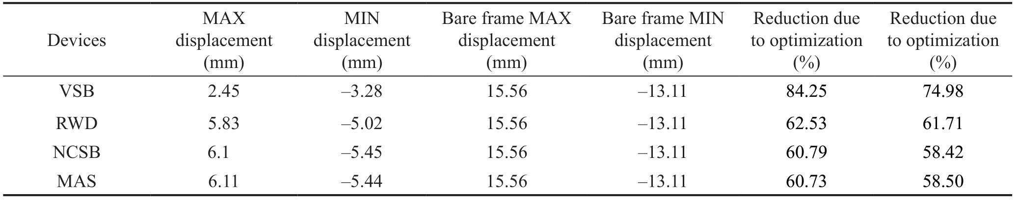
Table 9 Reduction of the maximum displacement during the optimization process in the x-direction
As can be seen in the results, the VSB device with an optimized design is able to perform the best action when compared with the other devices with a percentage of reduction around 99.9% and 84.25% for thezandxdirections, respectively. This means that the developed PSO-GSA optimization algorithm can successfully optimize the design of the vibration dissipation device to diminish nearly all the vibration effect on the structure.
The same conclusion can be drawn from the displacement results in thexdirection as shown in Table 9.
7 Performance comparison of the optimized dampers
As previously discussed, the optimization procedure for the considered three-story structure has been carried out in two steps as: (i) optimization of the structural seismic response and weight of the structure, and (ii) optimization position of the device within the frame.
The computation time for the first step of optimization for the considered three-story structure was about 12, 24, 20 and 16 hours for the VSB device, rubber wall damper, NCSB device, and MAS device, respectively.
Meanwhile, the optimizing process for the properties of the devices and the weight of the building were achieved through 390, 860, 720, and 550 iterations for the VSB device, rubber wall damper, NCSB device, and MAS device, respectively.
The second step of computation process took about 8, 9, 9 and 12 hours through 150, 200, 200 and 365 iterations for the VSB device, rubber wall damper, NCSB device, and MAS device, respectively, for optimizing the location of the devices within the frame.
The computation time depends on the number of variables for each device and the possible options of pentameters alteration. The number of iterations is also dependent on the efficiency of the developed PSO-GSA optimization algorithm to reach o the optimum results.
Figure 21 and Table 10 show the comparison between the different types of devices in terms of the percentage of maximum drift ratio in each floor. Figure 18 shows that the VSB device performed the best with 0.089, 0.00096 and 0.00036 percentage of maximum drift ratio for the third, second and first floor, respectively. Furthermore, all the devices managed to sustain a performance lower than 0.2%, which according to ASCE 7-10 Section 12.12.1 means that the building had no structural damage. The effects of the vibration dissipation device installed in the frame on the column forces, including axial force, shear forces, and bending moments during seismic excitation have been studied. The corner and middle columns (which the damper device is connected to its joint) at the ground floor (first floor) are considered to investigate the force variations during the seismic disturbance and the results are presented in Tables 11 and 12.
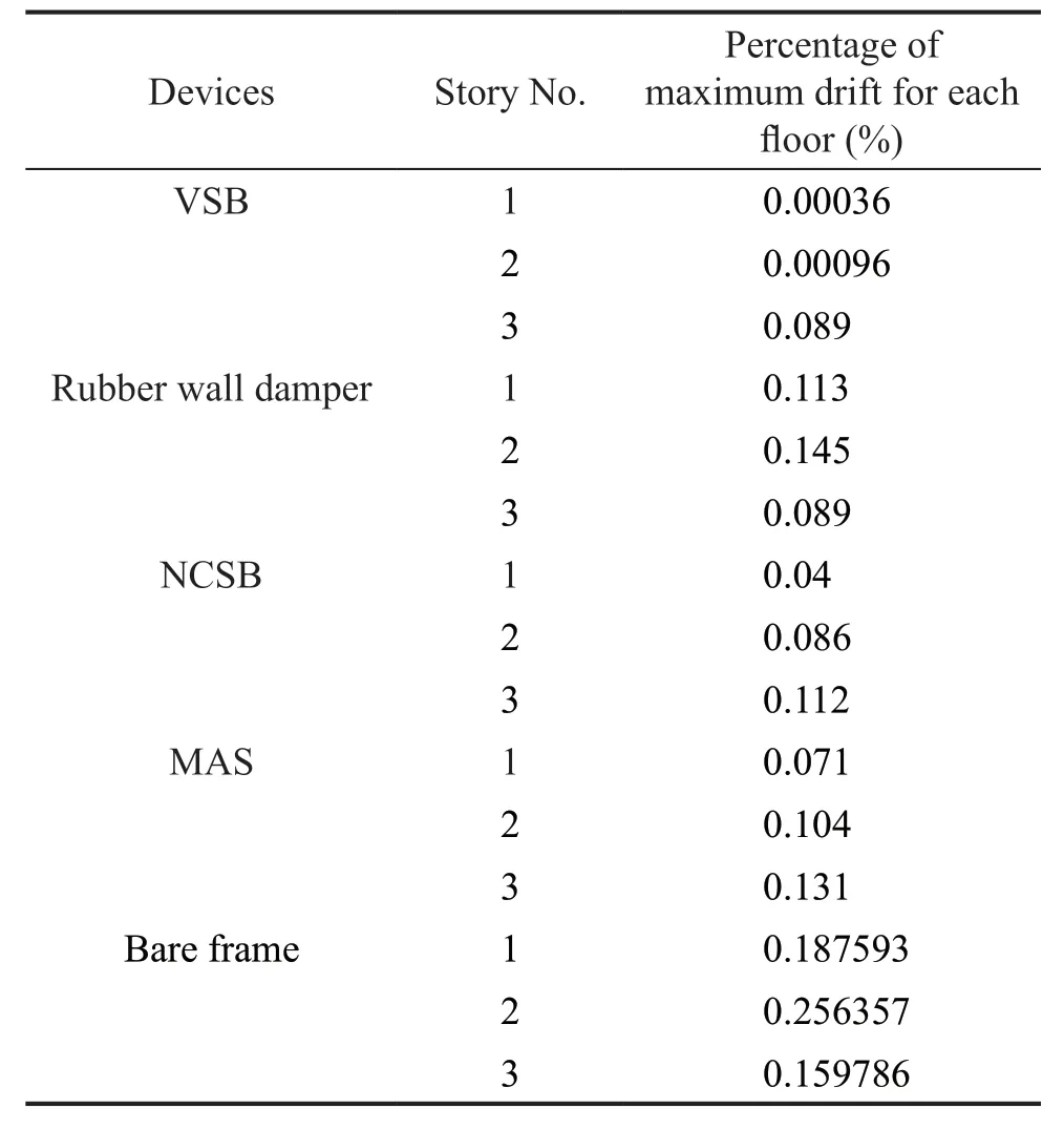
Table 10 Percentage of maximum drift for each floor (%)

Table 11 Maximum forces for each device in the column connected to the devices
To investigate the most critical structural member, the corner column is selected since it is subjected to axial force, base shear force and bending moment due to oscillation of structure. The middle column is considered, since the damper is connected to the bottom of the column and transfers shear force during vibration of the structure. It is obvious from results that the overall forces of both the middle and corner columns are decreased when the structure is equipped with the dampers. On the other hand, the forces for the braced frame decreases for the corner column when compared with the bare frame. Figures 22(a), 22(b), and 22(c) shows the peak axial force, shear force, and moment of the middle column in the frame structure for different dampers.
Figure 22(a) illustrates that the dampers have a significant effect on the axial force of the middle column. This corresponded to about an 89.71%, 37.18%, 36.29% and 48.48% decrease for the VSB device, rubber wall damper, NCSB device and MAS device, respectively. However, Fig. 22(b) shows that the overall shear force in the braced damper is less when compared with the bare frame by about 40.7%–97.5%. Furthermore, Fig. 22(c) shows that the overall moment force in the braced damper is lower when compared with the bare frame by about 55.9%–99.1 %.
Figures 23(a), 23(b), and 23(c) show the peak axial force, shear force, and moment of the corner column in the frame structure for different dampers in the corner column. Figure 23(a) shows that the dampers have an intermediate effect on the axial force of the corner column. The range of the decrease in the axial force fluctuates as seen in Fig. 23(a) and corresponds to about a 35.95%, 34.76%, 34.27% and 39.55% decrease for the VSB device, Rubber wall damper, NCSB device, and MAS device, respectively.
Moreover, Fig. 23(b) shows that the overall shear force in the braced damper is lower when compared with the bare frame by about 48.57%–72.84%. Additionally, Fig. 23(c) shows that the overall moment force in the braced damper is less when compared with the bare frame in the range of 58.86%–76.35%.
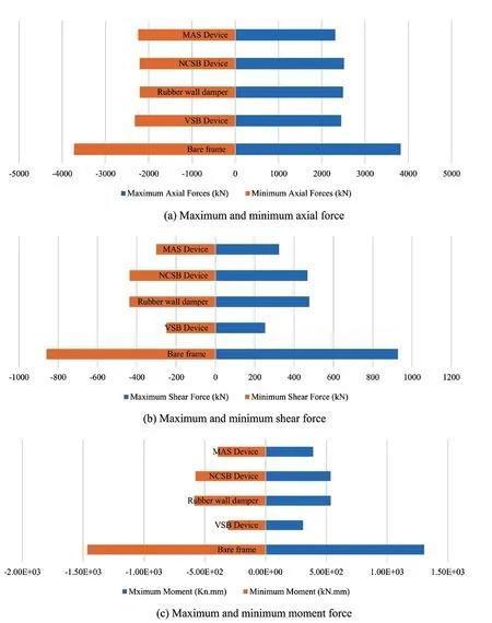
Fig. 23 Forces in the corner column
As shown in the results, the VSB device performs the best in decreasing the overall forces in the column when compared to the other devices as it corresponds to about a 89.7%, 97.46% and 99.11% decrease in the axial force, shear and moment, respectively. The huge reduction in the overall forces is due to inelastic actions of the nonlinear leaf springs in the VSB system, which exhibit more energy dissipation characteristics and provide more ductility for moment-resisting frames and created better dissipation energy when compared with the other proposed devices.
The proposed device employs four curved springs with nonlinear elastic deformations, and stiffness of the system can be changed by altering displacement, velocity and acceleration. Moreover, the braces will reduce the ductility of the frame. Therefore, the VSB technique allow the dissipation of energy via ductile action in the initial stage. The RWD device generates the dissipation force and damping force, which is lower than the damping force corresponding to the yielding force of the steel leaf spring. Similarly, the performance of the NCSB and MAS devices are based on elastic action of conical spring and coil spring, respectively, which act in an elastic stage and the damping force is lower than the yielding force of the VSB. Therefore, for these setups, the VSB shows better performance when compared to the other types of damper devices. However, the higher performance of VSB is highly dependent on the thickness of the leaf springs and the lower thickness may lead to the lower damping force but more ductility. Therefore, overall results for optimization depend on the geometry and characteristics of the structure. Moreover, depending on the demand of the structure for higher damping force or higher ductility, one of damper devices with optimum characteristics may be chosen through the optimization process to satisfy all earthquake design criteria for the structure.
8 Conclusions
The development of a hybrid optimization algorithm using a particle swarm optimization method and gravitational search algorithm (PSO-GSA) for structures equipped with supplementary vibrational damper devices is proposed to optimize the seismic damper types and characteristics simultaneously with optimizing the weight of the structure (beam and column section and steel rebar size). Four types of damper devices are considered in this study, including the variable stiffness bracing (VSB) device, rubber wall damper (RWD), nonlinear conical spring bracing (NCSB) device and multi-action stiffener (MAS) device. The main findings of this study are listed as follows:
(1) The optimization procedure for a structure with a damper device is made in two steps: (i) The first step optimizes the types and properties of the damper devices and the weight of the structure, which is calculated by beam-column sections size and steel rebar diameter. (ii) The second step optimizes the location of the damper devices in the structure frame.
(2) The first part of the optimization is completed through 390, 860, 720 and 550 iterations for VSB, RWD, NCSB and MAS devices, respectively, which took about 12, 24, 20 and 16 hours, respectively. The second step of the optimization was completed in 11 hours for each device for optimum location of the damper devices through 150, 200, 200 and 365 iterations for the VSB, RWD, NCSB and MAS devices, respectively.
(3) The outcome of this study regarding application of the developed optimization process on three-story RC frame proved that the reduction of plastic hinge occurrence in the structure with optimum devices during earthquake motion is 100%. It can be concluded that by using the selected optimum devices in a threestory structure, structural damage could be reduced by 100% which describes a fully resilient structure when compared to a frame designed using conventional methods. The result also indicates the weight of the structure was reduced in terms of the area of the column section, the area of the beam section, number of steel bars and the diameter of the bars, while also considering minimizing the displacement response of the frame during earthquake excitation.
(4) The analysis results show that the PSO-GSA successfully minimized the displacement in thez-direction in the range of 99.9%, 77.54%, 40.43% and 40.51% for VSB, RWD, NCSB and MAS devices, respectively. The total decrease in seismic response of the structure regarding the formation of plastic hinges in structural members in the building is approximately 99.63%, 60.5%, 79.13% and 57.42% for the VSB device, rubber wall damper, NCSB device, and MAS device, respectively. Additionally, the VSB device had the best action with 0.089%, 0.00096% and 0.00036% maximum drift ratio for the third, second and first floor, respectively. Furthermore, all the devices managed to sustain the performance of the structure in terms of keeping the story drift lower than 0.2%, which according to ASCE 7-10 Section 12.12.1, describes the building without any structural damage.
(5) Overall, the results of this study show that earthquake energy dissipation systems have been successfully optimized using the developed PSO-GSA optimization method and are able to mitigate the effects of lateral load on building structures. Therefore, safety of the building is improved, and its stability is significantly increased to endure the magnitude of vibratory motions during earthquake events.
(6) The performance of NCSB and MAS devices are based on elastic action of conical spring and coil spring, respectively, which act in an elastic stage and the damping force is lower than the yielding force of the VSB. Therefore, for these setups, the VSB shows better performance when compared to the other types of damper devices. However, the higher performance of VSB is highly dependent on the thickness of the leaf springs and the lower thickness may lead to lower damping force but more ductility. Therefore, the overall results for optimization depend on the geometry and characteristics of the structure.
杂志排行

Earthquake Engineering and Engineering Vibration的其它文章
- Dynamic shear modulus and damping ratio characteristics of undisturbed marine soils in the Bohai Sea, China
- Geotechnical engineering blasting: a new modal aliasing cancellation methodology of vibration signal de-noising
- Response prediction using the PC-NARX model for SDOF systems with degradation and parametric uncertainties
- Probability-based analytical model for predicting the post-earthquake residual deformation of SDOF systems
- Seismic behavior of multiple reinforcement, high-strength concrete columns: experimental and theoretical analysis
- Numerical study of a multiple post-tensioned rocking wall-frame system for seismic resilient precast concrete buildings