Mu-based trajectory tracking control for a quad-rotor UAV
2022-02-11AbdallahHossamAymanElBadawy
Abdallah Hossam·Ayman El-Badawy
Received:15 March 2022/Revised:7 June 2022/Accepted:13 July 2022/Published online:18 October 2022
©The Author(s),under exclusive licence to South China University of Technology and Academy of Mathematics and Systems Science,Chinese Academy of Sciences 2022
Abstract In this paper, the design and application of a robust mu-synthesis-based controller for quad-rotor trajectory tracking are presented. The proposed design approach guarantees robust performance over a weakly nonlinear range of operation of the quad-rotor, which is a practical range that suits various applications. The controller considers different structured and unstructured uncertainties, such as unmodeled dynamics and perturbation in the parameters. The controller also provides robustness against external disturbances such as wind gusts and wind turbulence.The proposed controller is fixed and linear;therefore,it has a very low computational cost.Moreover,the controller meets all design specifications without tuning.To validate this control strategy,the proposed approach is compared to a linear quadratic regulator(LQR)controller using a highfidelity quad-rotor simulation environment.In addition,the experimental results presented show the validity of the proposed control strategy.
Keywords Mu-synthesis·Robust control·H-infinity·Trajectory tracking
1 Introduction
The high maneuverability and ability of quad-rotors to access confined areas have led to their use in a wide range of indoor and outdoor applications.These applications include surveillance [1], inspection [2], search and rescue [3], agriculture[4],wildlife monitoring[5],firefighting[6],and exploration[7].However,it is challenging to design a controller for this system due to the highly nonlinear system dynamics, the communication and processing time delays,and the lack of exact knowledge of parameter values.Accordingly,a robust controller should be designed for safe operation of this system.
Many different control techniques were used to control the quad-rotor systems [8,9] including linear control techniques,suchasproportional-integral-derivative(PID)control[10],which has simple implementation and provides acceptable performance in the presence of minor uncertainties,and linear quadratic regulator (LQR) control, which is optimal with respect to a quadratic cost function[11].However,these methods require linearization of the system model around an operation point,which limits the range of operation of these controllers.In addition,these methods may require some tuning,if the system parameters are not exactly known.
In contrast, nonlinear control techniques typically cover a wide range of operation for multirotors.These techniques have been applied extensively on quad-rotors.They include backstepping control[12],which is a method used to derive a control law and the corresponding Lyapunov function recursively, to stabilize the system. In [13], a backstepping controller is designed for a quad-rotor system,and the controller is combined with a disturbance observer to improve the controller’s performance in the presence of disturbances.
Another nonlinear control technique is sliding mode control, which involves the alteration of the dynamic behavior of the system,such that it follows a selected sliding surface.A sliding mode controller was designed in[14]for a quadrotor.While in[15],a sliding mode controller that utilizes a nonlinear sliding surface was designed.From the presented results,both controllers showed acceptable performance.
The discussed nonlinear control techniques may result in reasonable performance over a wide range of operation.However,they do not have any form of optimization and usually require the tuning of some gains. In addition, in terms of implementation,the large number of nonlinear functions that need to be evaluated each time-step can result in high computational costs.
One widely used control technique is the model predictive control(MPC).This control technique uses a receding horizon over which it predicts the system behavior and calculates the optimal control action.In[16],a trajectory tracking MPC controller was developed for a quad-rotor. While in [17],another quaternion-based MPC controller was developed.According to the results,this technique can achieve acceptable performance. In addition, it can consider constraints in the optimal control problem. However, this technique requires solving the optimal control problem every time-step,which means that this method has high computational cost.This is a critical issue for systems with fast dynamics such as a quad-rotor.
Another optimal control technique is H∞control,which involves solving an optimal control problem by minimizing the H∞-norm of selected output signals over frequency.This results in an optimal linear controller that can achieve reasonable performance with low computational cost,since it is linear.Additionally,among the different control techniques,H∞-norm-based controllers can deal with uncertainties more naturally [18,19]. More specifically, H∞-norm-based techniques excel compared to other techniques, if there are unmodeled and neglected dynamics,which can be classified as non-parametric uncertainties.
Theμ-synthesis technique, which is based on H∞-synthesis,can achieve the specified performance criteria for a defined set of plants.This technique has been applied successfully in the literature on different systems, such as a nano-satellite system[20],where a comparison between H∞andμ-synthesis controllers is performed.The results showed thatμ-synthesis has higher robustness margins compared to H∞-synthesis. Aμ-synthesis controller is developed for a wind turbine system in [21], where parametric uncertainties are considered in the system model. A piezo-electric actuator-based active vibration control is developed using theμ-synthesis technique [22]. The controller considered hysteresis in the piezo-electric element. In [23], aμ-synthesis controller is developed for an inductive power transfer system. This controller considers inaccuracy in the mutual inductance parameters as uncertainty.
As for the quad-rotor system, different methodologies have been used to develop H∞-based controllers.Chen and Huzmezan[24]have developed a 2-degree of freedom(DOF)H∞controller for the attitude and altitude sub-systems of a quad-rotor, combined with MPC forxandy-axes tracking.However,the H∞controller proposed here is based on a simple linearized model, which limits the range of operation where performance is guaranteed. Another approach presented in[25],applied feedback linearization to the system,then designed the H∞controller based on the linearized system.However,in this work,H∞control was only used to improve robustness against disturbances and noise signals,while no uncertainties were considered.
Another work covered the development of an H∞-based controller for robust stabilization of a quad-rotor system[26]. The controller used Glover–McFarlane loop shaping procedure to achieve robust stabilization. This controller,however, does not guarantee robust performance. In addition, the controller considered communication time delays;however,neglected dynamics were not quantified.
In the literature, H∞optimal controllers for quad-rotors weremainlydesignedtoshapecertainsignalsoverfrequency,such as the error and the control effort signals. However,no work considered time delays,unmodelled and neglected dynamics, and parametric uncertainty in the design of aμsynthesis controller.These factors are important to consider,since they can affect the performance of any practical quadrotor system.
This paper presents the design of aμ-synthesis-based controller for quad-rotor unmanned aerial vehicle (UAV)trajectory tracking. The main contribution of this paper is that it presents the design methodology of a linearμ-based controller, which is synthesized based on a weakly nonlinear model that considers up to quadratic nonlinearities.This extends the operation range of the controller beyond that of linear models.In addition,the controller is robust to unmodelled dynamics and parametric uncertainties. Unlike MPC,which requires solving an optimization problem online,for example. The proposed controller is linear and fixed, so it requires low computational time.Simulations show that the proposed approach performance is excellent compared to an optimal fixed LQR control law. In addition, experimental results verify the practicality of the proposed approach.
The paper is organized in the following order.In Sect.2,the quad-rotor’s nonlinear model and linearized model are derived.Then,the attitude controller design and analysis are presented.Similarly,in Sect.3,the position controller design and analysis are presented. Afterwards, in Sect.4, the simulation and experimental results are discussed. Finally, the conclusion is provided in Sect.5.
2 Attitude control
In this section,the quad-rotor model is presented.Then,the attitude model is reformulated in a form suitable for theμsynthesis framework. Finally, the controller is synthesized via DK-iterations.
2.1 Full system model
The development of a model for the quad-rotor system is covered to a great extent in the literature[27,28].Therefore,only a brief overview of the model is provided in this section.Then,the perturbed model used in theμ-synthesis controller design is presented. Two coordinate frames are used in the model of the quad-rotor, the inertial frame that follows the north-east-down (NED) convention, where thex,y, andzaxes points towards the north, east, and downwards directions,respectively,andthebody-fixedframe.Bothcoordinate frames are shown in Fig.1,whereTidenotes the thrust of theith propeller, whileMx,My, andMzrepresent the torques about the body-fixed frame’sx,y,andzaxes,respectively.In addition,the vectormg represents the weight of the quadrotor.Accordingly,the state-space model is given as follows[28]:
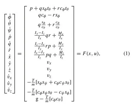
where the first six equations represent the rotational dynamics, while the last six equations represent the translation dynamics. The symbolsp,q, andrrepresent the angular velocity about the body-fixed frame’sx,y, andz-axes,respectively;the statesx,y,andzrepresent the position of the quad-rotor;vx,vy, andvzrepresent the velocity of the quad-rotor in the inertial frame.Moreover,Ix,Iy,andIzare the moments of inertia around the body-fixed frame’sx,y,andzaxes,respectively,whileTdenotes the summation of all thrust forces from the four propellers.Note thatcx,sx,andtxdenote cosx,sinx,and tanx,respectively.However,the model representation derived in this subsection is not suitable for theμ-synthesis framework. Therefore, in the next subsection,the attitude model is placed in a form suitable for the linearμ-synthesis framework.
2.2 Perturbed attitude model formulation
This subsection covers the derivation of the perturbed attitude model to be used in controller design. It should be noted that according to the model described in (1), the attitude sub-system,given by the first six equations,is independent of the position sub-system. Accordingly, only the attitude sub-system is considered in the design of the attitude controller. This results in this new set of statesx=[φ θ ψ p q r]T.Additionally,the inputs of this sub-system areu=[Mx My Mz]T,while the measured outputs for the attitude sub-system are the Euler angles,which are given by the output vectory=[φ θ ψ]T.
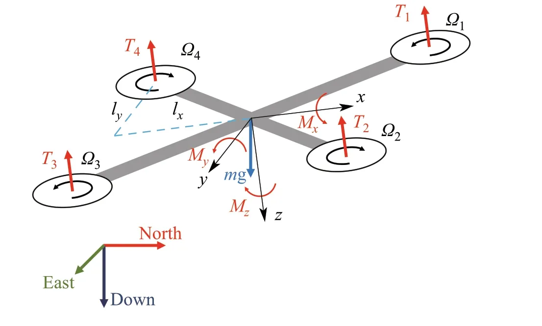
Fig.1 Quad-rotor forces and moments
It is proposed to consider a weakly nonlinear range of operation for the attitude angles of the quad-rotor to extend the robust performance beyond the linear range of operation and to achieve a range of operation suitable for many applications.To consider the weakly nonlinear range of operation,it is proposed to linearize the model over a region in the statespace rather than a single point of operation.To this end,the linearization point values are represented in terms of parameters that can have any value within a specified range as shown in(2)wherec0isthenominalvalue,wisaweightwhichdetermines the magnitude of variation, andδis a normalized variable,suchthat‖δ‖<1.This representationis identical tothat used for representing parametric uncertainty within the model as well.

The linearized state-space modelAandBmatrices are provided in (3) and (4). Note that theAmatrix (3) contains trigonometric functions in terms of the linearization point variables ¯φand ¯θ,which are not suitable for the linearμ-synthesis framework.Therefore,it is proposed to replace these trigonometric functions with polynomials that can be used in theμ-synthesis framework via repeated uncertain variables through linear fractional transformation(LFT)[29]
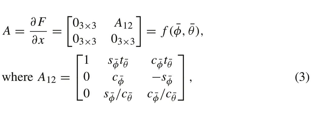
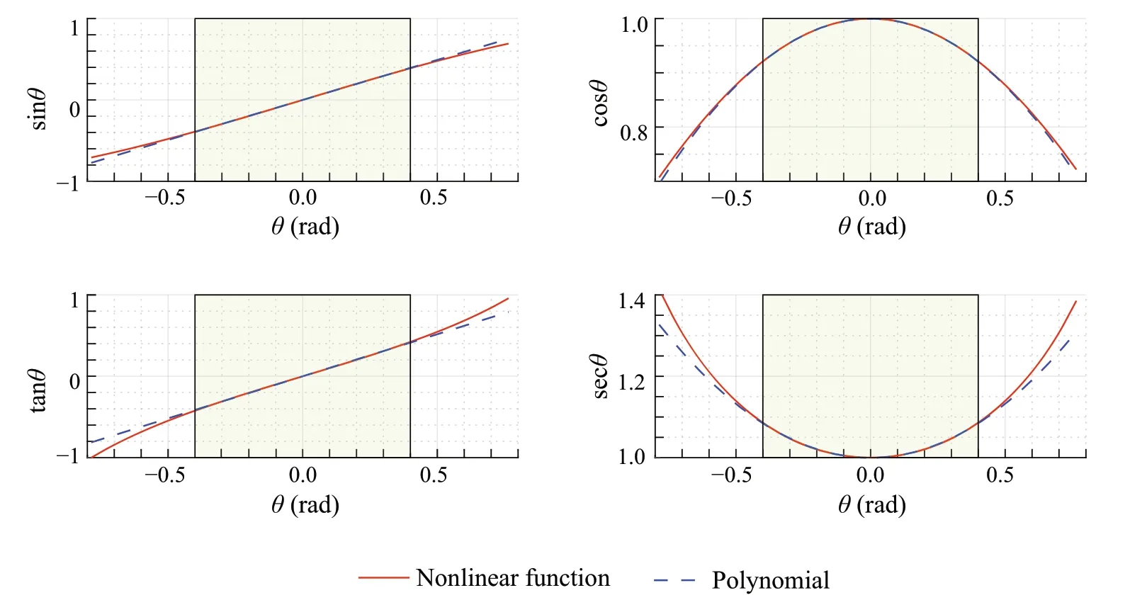
Fig.2 Curve fitting polynomial graphs

The proposed weakly nonlinear range of operation is set to±0.4rad for the roll and pitch angles as it allows up to half of the thrust force to be projected into the horizontal plane.The polynomials are curve fit to match the corresponding trigonometric functions. Results of the curve fitting are shown in Fig.2.
As can be seen, the curve fitting is accurate within the specified range of linearization shaded in the figure. Note that the maximum polynomial degree is set to 2. However,thecurvefittinghasacceptableaccuracyaccordingtoTable1.In addition,the moment of inertia and the mass are assumed to have a value within a specified range,to ensure robustness against variation in these parameters.The full list parameters are given in Table 2.
To make the attitude model state-space matrices, shown in (3) and (4), suitable for theμ-synthesis framework, all trigonometric functions are replaced with the corresponding polynomial functions;afterwards,all variables which are found in Table 1 are replaced with the parametric uncertainty representation of the form shown in(2).This results in an attitude model which contains 18 occurrences of uncertain parameters in its representation.As demonstration,the equivalent representation of theA12sub-matrix is provided as follows:such thatδφandδθrepresent the normalized uncertainty representation regarding the roll and pitch linearization points,respectively. While theBmatrix contains three uncertain parametersIx,Iy, andIz, respectively. This representation allows theμ-synthesis to consider a set ofAandBmatrices that represent the set of different possible plants when synthesizing the controller.With this model,the generalized plant can be derived, and accordingly, theμ-synthesis controller can be synthesized.
2.3 Attitude generalized plant derivation
The perturbed model developed in Sect.2.2 is utilized in the general control problem formulation to consider the weakly nonlinear range and uncertainty in the values of the mass moment of inertia,as mentioned previously.In this subsection,several technical problems in the model formulation are resolved and theμ-synthesis problem is fully defined. The first thing to note about the perturbed attitude sub-system is that it contains double integrators, which are equivalent to two poles at the origin,since this is a dynamic system.This results in the H∞-synthesis problem being ill-conditioned,preventing the synthesis of a stabilizing controller [30].Therefore,it is proposed to pull these imaginary-axis poles into the left-half plane using a lead compensator.The inner loop is shown in Fig. 3,whereKLis the lead compensator,whileG pis the perturbed plant.


Table 1 Curve fitting polynomials for trigonometric functions
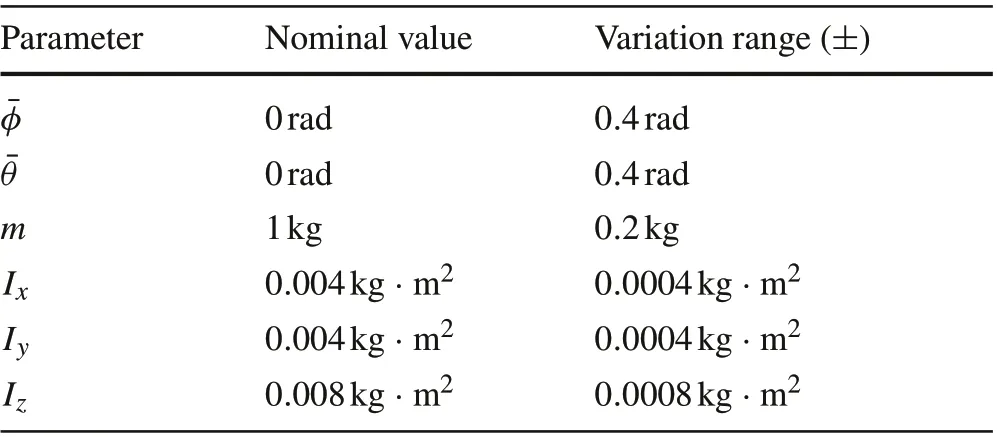
Table 2 System model parameters
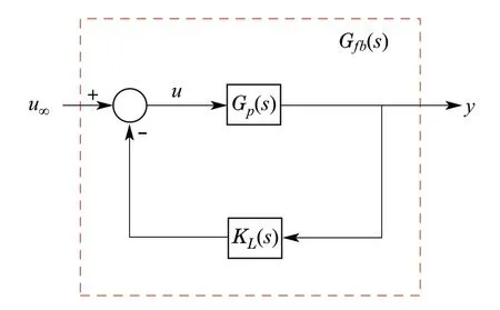
Fig. 3 Inner control loop to pull imaginary-axis poles into left-half plane
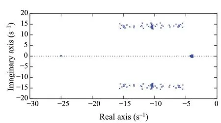
Fig.4 Pole-zero map for samples of the closed-loop perturbed plant
By applying the inner loop controllerKL,the new equivalent systemG f b(s) does not contain any imaginary-axis poles anymore.As can be seen from Fig.4,all poles of the equivalent system are in the left-half plane.
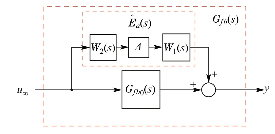
Fig.5 Additive uncertainty representation form
According to the perturbed model, there are 18 occurrences of uncertain parameters, and these parameters are considered as real perturbations in the model.As a result,this introduces numerical difficulties in theμ-synthesis algorithm[18].Accordingly,it is proposed to lump all these uncertainties into a single complex unstructured uncertainty block.This results in a simple system representation,in addition,it reduces the total number of uncertain elements in the system.The equivalent system representation is set into the additive uncertainty form shown in Fig.5.
The additive uncertainty representation consists of a nominal model,denotedG f b0(s),and an uncertainty termEa(s).These two transfer matrices are added to represent the total uncertain modelG f b(s). The nominal model,G f b0(s), is defined by replacing the plantG p(s)in Fig.3,with the nominal plant.While the uncertainty blockEa(s)is defined as

Accordingly,the uncertainty upper bound can be defined by

whereΠis the set of plants defined by Table 2. Note thatG f b(s)is defined in terms ofG p(s).Finally,the uncertainty upper bound is represented in the form

whereW1(s) andW2(s) are transfer matrix weights that define the magnitude of uncertainty in each input–output channel andΔ(s) is a diagonal matrix defined, such that||Δ||∞<1.To determine the transfer matrixW1(s),worstcase gain analysis is performed to define an upper bound on the magnitude of the uncertainty.Afterwards,low-order transfer functions are curve fit to these upper bounds for each input–outputchannel,asshowninFig.6.Notethat,according to the model,the inputMxis not coupled to the pitch and yaw channels.Accordingly,there is no uncertainty in the transfer functions fromMxtoθandψ. Based on this uncertainty representation,only seven complex uncertainty elements are required inΔ(s).Finally,the matrixW2(s)is selected to be a selector matrix that consists of identity matrices,such that(9)is satisfied.
With the uncertain model fully defined, the generalized plant can be formulated.A signal-based approach is adopted for the problem definition, where the focus is on the magnitude of selected signals over frequency. The exogenous output signalszto be shaped over frequency are selected to be the error signals and the control effort signals.Note that the control effort signal consists of two parts,the output of the lead compensator and the output of theμ-synthesis controller.Accordingly,z2is defined as in(11)and the signalszare defined as follows:

whereWpandWuare transfer matrix weights that set an upper bound on the magnitude of the error and control effort signals respectively.While the signalsr,y,ymandu∞are the reference, the true output, the measured output, and theμsynthesis controller output, respectively. Note that the true output is a theoretical signal only used in the definition of the error; however, the measured output is the signal used by the controller.Moreover,the exogenous inputs applied to the system are the reference signalr,the disturbance signald, and the noise signaln. ThePKΔform of the system is shown in Fig.7, wherePis the generalized plant,Kis theμ-synthesis controller,andΔis the normalized uncertainty block.Note thatKis a two-DOF controller that takes as an input the reference signalrand the measured output signalym.The system model shown in Fig.5 is the one used in thePKΔform.However,theW1(s)Δ(s)W2(s)term is placed in a reversed order to match the general control problem form.In addition,uis the total control effort signal;therefore,the term −KL(s)ymis included to take into consideration the control effort of the lead compensator introduced in the inner control loop,as shown in thePKΔform.
Beforeμ-synthesis can be performed, it is required to define the weight transfer matrices shown in Fig.7. First,note that the disturbance ˜d,reference ˜rand noise ˜nare scaled by weighing matricesDd,R, andDn(s), respectively. The matrixDdis selected to consider an external disturbance with a magnitude of 1%of the maximum control effort,whileRis set to an identity matrix,where

where error,reference,and control effort signals are normalized using scaling matricesDe,Dr, andDu, respectively.
The matrices are defined as follows:

The noise signal ˜nis scaled using a transfer matrix weightDn(s),which has the form

wherewn(s)is a weight transfer function which determines the frequency content of the noise signal.It is assumed that noise is a high-frequency phenomenon;as a result,the weightwnis selected to be a high-pass filter given by

such that the magnitude of noise at high frequencies is set to 5%of the maximum expected measurement signal.Moreover,the error weight is selected,such that the error has small value for a defined low-frequency region,while the error signal is bounded in the high-frequency region. The weights used inWp(s)are selected for the roll and pitch channels to be first-order transfer function weights[18]given by

with a bandwidth value of 6.1rad/s, a low-frequency error upper bound of 0.1%and a high-frequency error upper bound of 2.While for the yaw channel error,weight is selected to be a second-order transfer function weight given by

where the bandwidth is set to 0.5rad/s. Accordingly, the transfer matrixWp(s)is defined as a diagonal matrix

Finally,the control effort signal is shaped using the weighing matrixWu(s),such that at low frequencies,there are no constrains on the control effort signal,ensuring integral control behavior, while at high frequencies, the control effort magnitude is bounded.The transfer matrix is selected as follows:

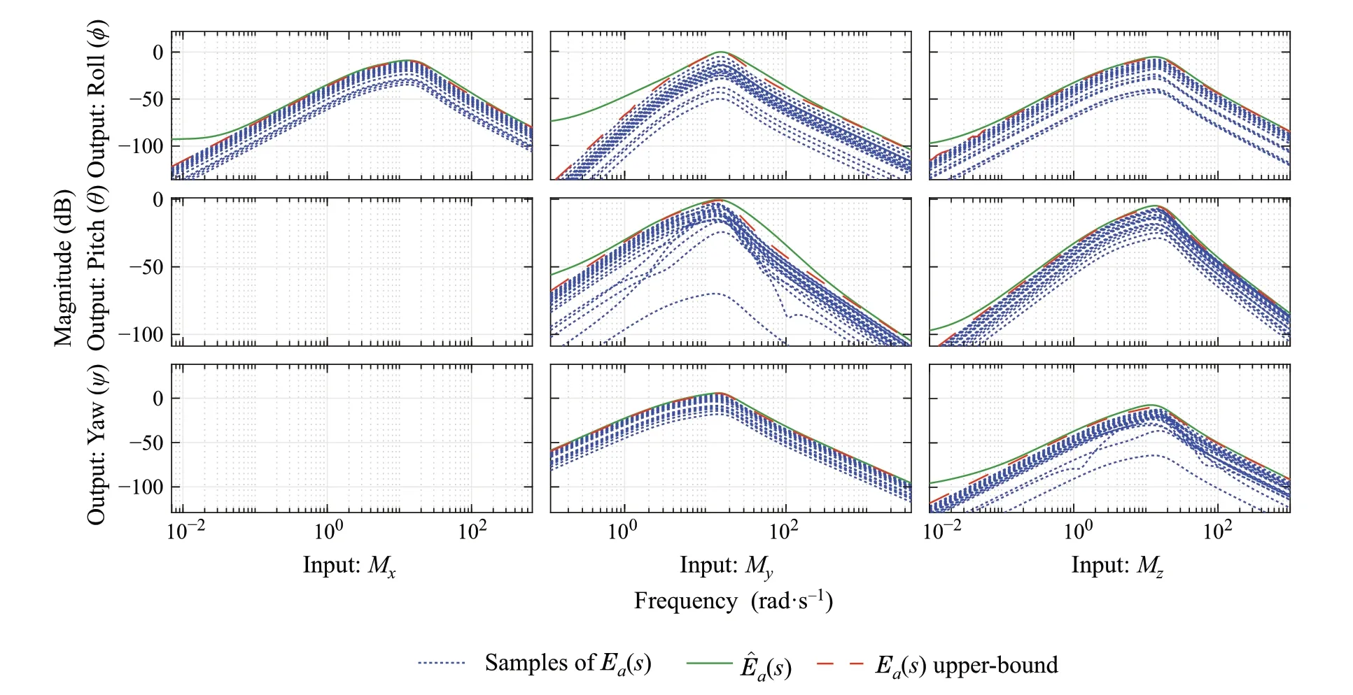
Fig.6 Worst-case analysis for Ea(s)and its upper bound(s)
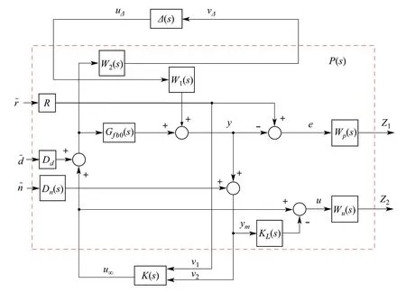
Fig.7 PKΔ form of the orientation sub-system
wherewu(s)is given by

Finally, with the generalized model fully derived, DKiterations can be used to synthesize the controllers as in the next section.
2.4 DK-iterations
Theμ-synthesis problem is still not fully solved; however,a practical approximation of this problem can be solved through an iterative algorithm known as DK-iterations[31].The main concept of this technique is that an upper bound on the structured singular valuesμcan be defined as


Table 3 DK-iterations summary for attitude controller
whereNis defined as the LFT ofP(s)andK(s)[18],andDis a scaling transfer matrix selected optimally to find the least upper bound ofμ,such that instead of minimizing the structured singular values, the scaled infinity norm can be minimized.Accordingly,the DK-iterations algorithm can be defined by the following steps[32]:
1. Set an initial scaling matrixD.
2. Synthesize an optimal H∞controller for the scaled systemDN D−1.
3. Find the scaling matrixD(jω)which minimizes the upper bound in(23)over all frequencies.
4. Curve fit a stable low-order transfer functionD(s) toD(jω).
5. Return to step 2 for the next iteration.These iterations are performed until either theμ-upper bound is less than 1, which means that robust performance is achieved, or the upper bound does not decrease anymore.The iteration summary for the attitude controller is shown in Table 3. As can be seen from the table, theμ-upper bound decreased from a value of 1.14 to 1 in the second iteration,which means that robust performance is achieved.Therefore,the controller from the second iteration is used.However,this controller has an order of 84,which means that this controller requires high computational effort.
Therefore,toreducetherequiredcomputationaleffort,itis proposed to reduce the controller order via the balanced truncation model reduction technique [33]. The reduced order controllerKr(s)has an order of 25 with a maximum absolute error valueEless than −40dB.The maximum error is defined by

whereωis the frequency variable, ¯σis the maximum singular value,K(jω) is the full order controller, andKr(jω)is the reduced order controller. The full order and reduced order controllers’ singular values are shown in Fig.8. Note that since the controller size is 3 × 6, the controller has three singular values. As can be seen from the figure, the singular values for both controllers almost overlap over frequency, which means that the reduced order controller is a good approximation of the full order controller.
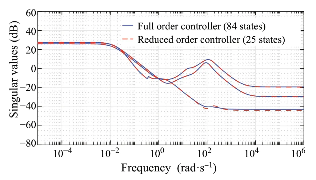
Fig.8 Full and reduced order controllers’singular values’plot
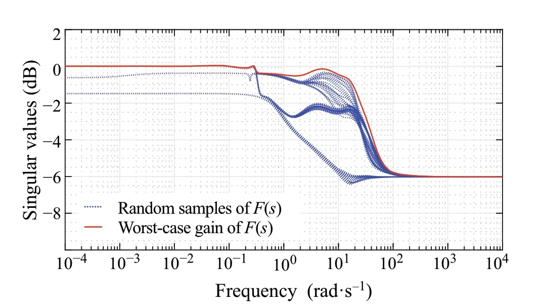
Fig.9 Worst-case gain analysis for closed-loop system with reduced order controller
Finally, it is important to check that the reduced order controller still achieves robust performance,this is done via worst-case gain analysis to check that the infinity norm of the closed-loop system does not exceed unity for the defined uncertainty set. The maximum singular value is shown in Fig.9. According to the graph, the infinity norm achieved by the reduced order controller is still unity, which means that robust performance is achieved by this reduced order controller.
3 Position control
The quad-rotor system is an under-actuated system with four actuators and six DOFs. Accordingly, only four DOFs are tracked simultaneously. Therefore, it is proposed to apply the position control in cascade,such that thex,y,andzposition are controlled through the roll and pitch angles and the thrust force.A schematic diagram that describes the control architecture is shown in Fig.10.
3.1 Model representation
The position sub-system consists of the last six stateequations described in (1). To facilitate controller design,a transformation is used to simplify the position sub-system

Fig.10 Cascade control architecture for trajectory tracking
model.The model is described by
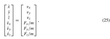
whereFx,Fy, andFzare forces in thex,y, andz-axes,respectively,which are given by

First, note that the force due to the quad-rotor’s weight is canceled by applying a constant force value in thez-axis equal to the quad-rotor’s nominal weight, while the rest of the weight due to uncertainty in the mass is considered as an external disturbance.Accordingly,the controller is designed in terms of these forces based on(25).Afterwards,given the current yaw angleψ,the forces required by the controller are mapped into a reference thrust force (T) and reference roll(φ)and pitch(θ)angles.
The relation for these references is derived by solving Eqs.(26)–(28)for the roll,pitch,and thrust variables in terms of the forcesFx,Fy, andFz. The first relation is derived according to Pythagoras theorem in three-dimensional space as follows:

To derive the second two relations for the pitch and roll references,θis separated in(27)

whereφdandθdare the reference roll and pitch angles,respectively. By substituting (30) into (26), an expression forφdis obtained

After obtainingφd, the reference pitch angleθdcan be obtained by substitution into(30)

However,expression(32)is singular forψ=nπ,wherenis an integer.Therefore,another expression can be derived forθdfrom(26)as follows:

Finally,given the forces required by the controller in thex,y, andzdirections, the reference roll and pitch angles and thrust force are calculated according to(29)and(31)–(33).This simplifies the position sub-system model and makes it suitable for the derivation of the generalized plant as discussed in the next section.
3.2 Position model uncertainty formulation
As can be seen from the model described in (25), the only uncertain parameter is the massm. It is assumed that the mass has a nominal value of 1kg and an uncertainty range of ±0.2kg. The state-space representation of the model is given by
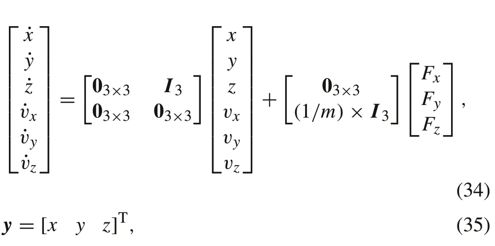
wheremis an uncertain parameter. With reference to the experimental setup, position measurements are obtained from a vision-based tracking system;therefore,the measurements received are expected to be delayed due to processing and communication.Accordingly,to ensure the reliability of the controller, it is proposed to include a time delay in the model.The model described in(34)and(35)is transformed from the state-space representation into a transfer matrix.In addition,the time delay is applied to the system as a multiplicative term


whereθis the time delay in seconds.It is important to note that the time delay function(37)is of infinite dimension;as a result, it is proposed to use a delay-free nominal model and represent the delay as output multiplicative uncertainty.Accordingly, only an upper bound onf(s) is required to be derived,which can be defined using a low-order transfer function.The output multiplicative uncertainty form is

whereΔ(s)is the normalized uncertainty block,whileWo(s)sets an upper bound on the magnitude of uncertainty due to time delay.The uncertainty is assumed to be diagonal,since there is no coupling between the output channels due to the time delay.Accordingly,the weightWo(s)is selected to be

wherewo(s) is a weight that sets an upper bound on the uncertainty[18],which is given by

whereθmaxis the maximum expected delay value in seconds,such that|wo(jω)|≥|1−e−jωθmax|for all frequenciesω.The delay value to be considered isθmax= 10 ms. The magnitude plot for both quantities is shown in Fig.11. As can be observed from the plot,the weightwo(s)sets a tight upper bound on the magnitude of uncertainty.
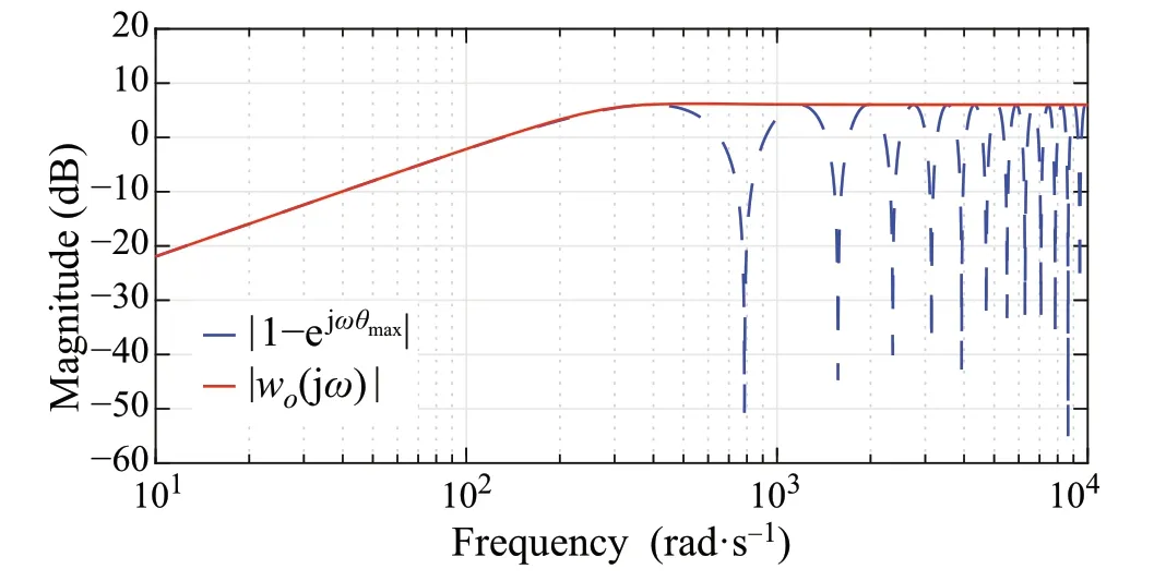
Fig.11 Delay and multiplicative uncertainty weight comparison
With this perturbed plant definition,the generalized plantPcan now be defined.The problem definition is similar to that of the attitude control, with the main difference being that the controller used for position control is a single DOF controller.ThePKform of the position sub-system is shown inFig.12.Theblockdiagramonlyshows thePandKblocks;however, it is important to note thatG p2(s) contains the uncertain parametermand the uncertainty representation of the time delay as described by(38)–(40)
Similar to the attitude model, the signals are normalized using weight matrices as in(12)–(15).The weights are defined as follows:

whereDe2is the position error scaling matrix,Dr2is the reference scaling matrix,andDu2is the control effort scaling matrix. In addition, the noise signal weightDn2(s) has the form

where

The error performance weight is given by

wherewp2(s)is a second-order weight given by

such that the error signal bandwidth is set to 1rad/s.Moreover,the control effort signal weight is given by

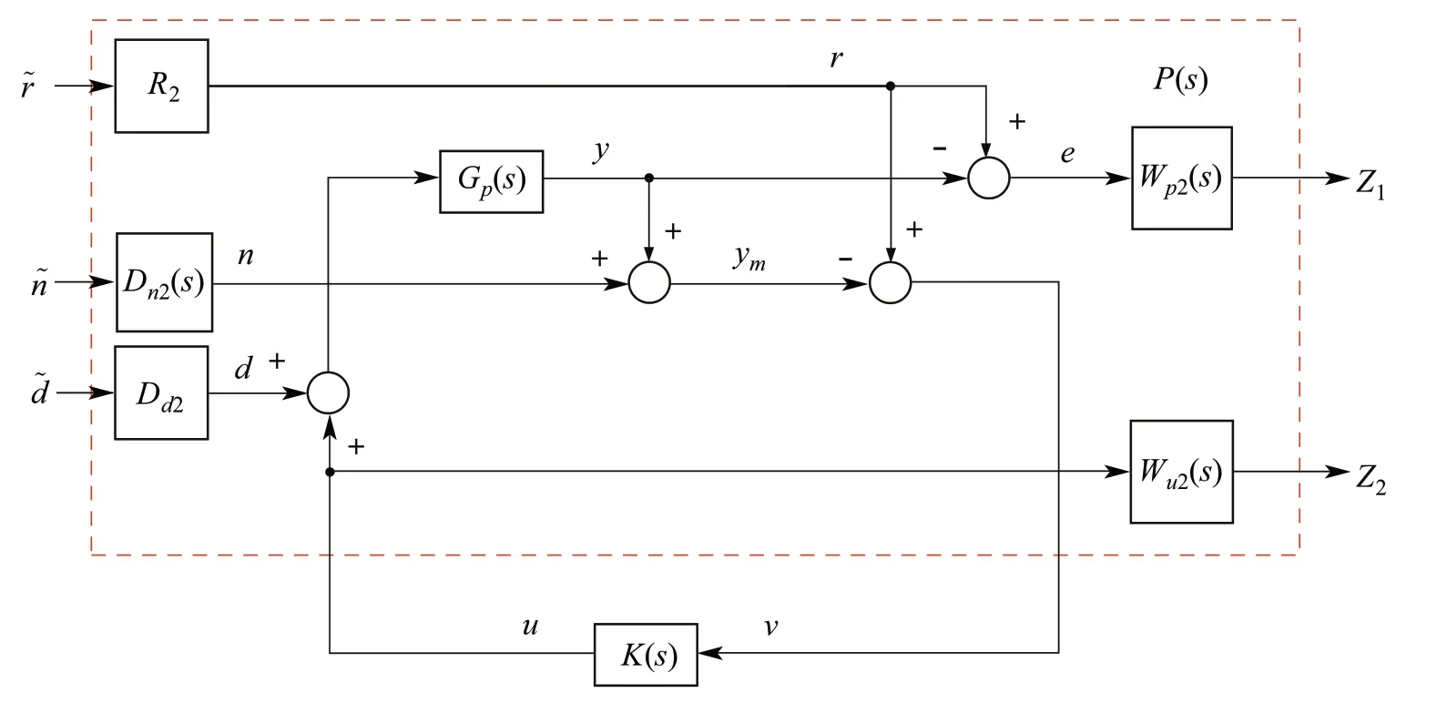
Fig.12 Position controller PK formulation block diagram

Table 4 DK-iterations summary for position controller
where

such that the control effort is bounded for frequencies greater than 10rad/s. This frequency is selected, since the control effort signal produced by the position controller is used in cascade with the attitude controller. Accordingly, the output of the position control should have limited bandwidth.Finally,similar to the attitude controller,aμ-synthesis controller is synthesized usingDK-iterations.Before applying the DK-iterations,a bilinear transformation is applied on the system to avoid problems due to imaginary-axis poles[30]

wheresistheLaplacetransformvariable,˜sisthetransformed variable,andαis a small real positive number.The iterations summary is shown in Table 4.
Note that the controller from the third iteration has aμupper bound of 1.02.Before using this controller,the system must be transformed from the ˜s-domain to thes-domain via the inverse bilinear transformation as defined by(50).Afterwards,μ-analysis is performed and theμ-upper bound in thes-domain was found to be 1, which means that robust performance is achieved.Note that to reduce the computational effort required,the controller order is reduced from 48 to 15 via the balance truncation model reduction technique.
4 Simulation and experimental results
In this section, the proposed controller is validated using a realistic simulation environment.The environment is developed in MATLAB Simulink and includes a realistic wind model as a source of disturbance. This section includes a description of the simulation environment, the simulation scenarios, and evaluation metrics. Afterwards, presentation and discussion of the results are provided.Finally,the experimental setup is presented,and the experimental results are discussed.
4.1 Simulation environment
The simulation environment includes a nonlinear six DOF model of the quad-rotor system as described by (1). In addition, Dryden wind turbulence model is included in the environment to provide a realistic disturbance model [34].The implemented wind velocity model consists of two components,the wind gust and the turbulence wind.Throughout this subsection,subscriptjdenotes any of the three inertial frame axesx,yorz.
The discrete wind gust model is used to represent changes in the mean velocity of the wind. The wind component in each axis is given as follows:

wind velocity wave forms[35]
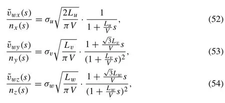

wherev jis the quad-rotor’s velocity with respect to the inertial frame’sj-axis andvwjis the total wind velocity in the inertial frame’sj-axis,such that

The termsσu,σv, andσware the turbulence intensities. At low altitudes,they are calculated as follows:

whereW20is the wind speed at 6m altitude andzis the height of the quad-rotor.The termsLu,Lv,andLware the turbulence scale length which are given by

The generated wind velocity is used to calculate the drag forces on the quad-rotor according to the following expression:

whered jis the aerodynamic drag force,ρis the air density,Cdis the drag coefficient,andA jis the area of projection.All terms are represented in the inertial frame’sj-axis.The drag coefficient is obtained based on the assumption that the quadrotor’s body has a cubic shape[36].A typical value for the coefficient of drag of a cube having an arbitrary orientation relative to wind is 0.9. Therefore, this value is selected for the simulation.Moreover,the projection area in the inertial frame is related to the projection area in the body-fixed frame by the following equation:

whereAi= [Ax,Ay,Az]Tis the projection area vector in the inertial frame,Ab= [Abx,Aby,Abz]Tis the projection area vector in the body-fixed frame,and ¯Ris given as follows:

4.2 Baseline LQR controller design
To assess the performance of the proposed controller, it is compared to a baseline LQR,since it is an optimal fixed linear controller.The same architecture used for theμ-synthesis controller is also used for LQR.The LQR is an optimal state feedback controller[37],which solves an optimization problem that minimizes the performance index

wherex(t)isthesystemstates,u(t)isthecontroleffort,Qisa positive-definite or positive semi-definite weight matrix that specifies the importance of minimizing the error in each state,andRis a positive-definite weight matrix that identifies the importance of minimizing each of the control effort variables.The weight matricesQandRin(62)are selected according to Byrson’s rule[38],which states that we can selectQandRto be diagonal matrices with theith diagonal elementdirepresented as follows:

whereδmaxiis the maximum allowable value for the correspondingith element’s state error or control effort for theQandRmatrices, respectively. For the attitude sub-system,the maximum allowable values for the error and control effort signals are the same values used for theμ-synthesis controller scaling matrices defined by (12)–(15), which are given byQ= diag{[1/0.32,1/0.32,1/0.32,1,1,1]} andR= diag{[1/0.52,1/0.52,1/0.32]} for the attitude subsystem. Similarly, for the position sub-system, the weights are defined asQ= diag{[1/0.32,1/0.32, 1/0.32,1,1,1]}andR= diag{[1/62,1/62,1/62]},which are similar to the matrices given by(41)–(43).This ensures that error signals are within similar bounds and that control effort signals of boththeLQRandμ-synthesiscontrollersshouldhavesimilar magnitudes.
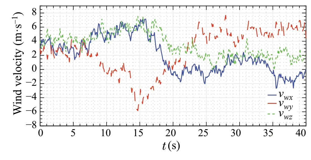
Fig.13 Wind velocity applied on quad-rotor during test scenario
4.3 Simulation scenario and metrics
The simulation scenario includes tracking of a spiral trajectory,which consists of continuous climbing in thez-axis direction,while performing circular motion in thexy-plane.In addition,the quad-rotor is subject to different types of disturbances as discussed below. The simulation is performed for both the proposed approach and the baseline LQR controller for comparison.The initial position of the quad-rotor is[−1 0 1]Tm to test the controllers given large initial error.The position reference trajectory is given by

while it is required to maintain the yaw angleψat 0rad.The wind disturbance applied to the quad-rotor starts with a mean velocityvm= [3 3 4]Tm/s represented in the inertial frame. Afterwards, a wind gust of mean velocityvm= [2 −6 2]Tm/s starts att= 5s with a gust duration ofT= 10s. Then, att= 15s, a wind gust starts that generates wind velocity ofvm= [−4 8 −4]Tm/s, withT= 10s.The turbulent wind velocity waveform generated during the simulation is shown in Fig.13. In addition, the wind disturbance force on the quad-rotor is shown in Fig.14.
In addition to wind disturbance, an eccentric load is attached to the quad-rotor, which results in a disturbance torque of −0.02Nm in thex-axis. Moreover, to test the control strategy under the effect of time delay, a delay ofτ=20ms is applied to the position measurement signals.
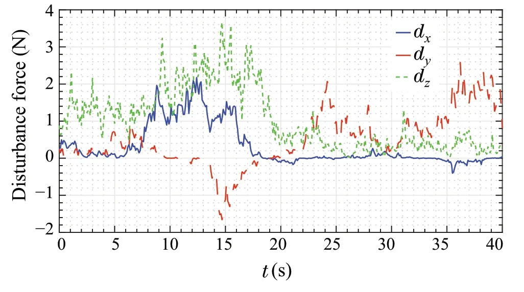
Fig.14 Disturbance force due to wind applied on the quad-rotor
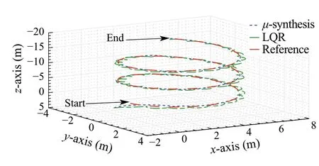
Fig.15 Trajectory tracking position three-dimensional plot
The simulation scenario is performed twice. Once with nominal model parameters,and another time with the worstcase H∞gain parameters,which should result in the worstμsynthesis controller performance to assess the performance against parametric variation.
The controller performance is evaluated based on the rootmean-square error (RMSE) for the Euclidean distance and the attitude angles.In addition,the control effort is evaluated based on the maximum absolute value.Which should remain less than 20N for the thrust force,while it should remain less than 0.5 N m for the body-fixed framexandy-axes,and less than 0.3 N m for thez-axis.
4.4 Nominal model simulation results
The position tracking plot is shown in Fig.15.As can be seen from the plots,the LQR controller trajectory deviates significantly from the reference,while theμ-synthesis controller trajectory remains close to the reference trajectory.The LQR controller resulted in an RMSE value of 0.27 m, while the proposed approach achieved an RMSE value of 0.2 m.The error is calculated in terms of the Euclidean distance between the reference and actual positions.
The position error for each axis is plotted in Fig.16.It is important to note how the LQR controller resulted in large error values compared to the proposed approach, particularly in thexandyaxes. This is mainly due to the LQR being unable to deal with the time delay and the different types of disturbances effectively.Accordingly,this validates that the proposed approach has better disturbance rejection capabilities compared to the LQR controller.In addition,theμ-synthesis controller is capable of handling time delays in measurements without deterioration of performance.
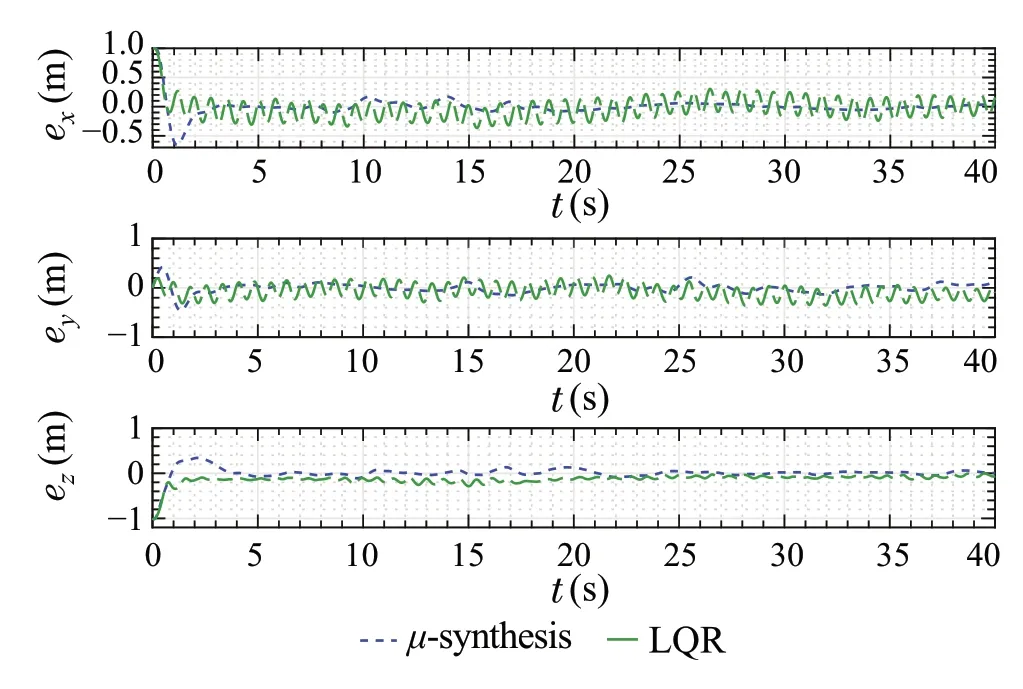
Fig.16 Position tracking error signals
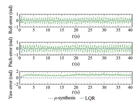
Fig.17 Attitude tracking error signals
The attitude tracking error plots for both the LQR controller and the proposed controller are shown in Fig.17.As can be observed from the plots, the error value of the proposed controller is much lower than the values of the LQR controller. Note how the LQR error signals are oscillatory due to overcompensation, which is happening due to time delay in measurements. The RMSE values obtained by the LQR controller are 0.28rad,0.31rad and 0.88rad for the roll,pitch,andyawchannels,respectively,whiletheRMSEvalues obtained by the proposed controller are 0.042rad,0.056rad,and 0.006rad for the roll, pitch, and yaw channels, respectively.Due to the coupling between the angles in the attitude model,the LQR controller fails to eliminate the steady state error in the yaw axis.
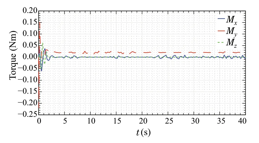
Fig.18 Torque signals of μ-synthesis controller
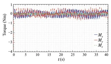
Fig.19 Torque signals of LQR controller
The torques produced by theμ-synthesis controller about thex,y,andz-axes are shown in Fig.18.As can be observed,the peak torque value achieved byμ-synthesis is about 0.2Nm, while the maximum torque value achieved by the LQR controller reaches a peak value of 3Nm, as shown in Fig.19. This is due to the large initial position error value.In addition,the LQR controller produces large control effort values of about 0.5Nm,due to its inability to overcome the effect of time delay in measurement signals.This also indicates that theμ-synthesis controller generates a more feasible control effort signal.
In addition, the thrust force produced by the proposed approach and the LQR controller are shown in Fig.20. It is important to note that the thrust force achieved by both controllers are within the feasible range.Moreover,by comparing the LQR andμ-synthesis control effort signals, it should be noted that theμ-synthesis controller produces more feasible thrust signal compared to LQR.
The results shown in this subsection are for a quad-rotor with the nominal inertial parameters. To test the controller against parametric uncertainty, another simulation is performed,as shown in the next subsection.
4.5 Worst-case gain model simulation results
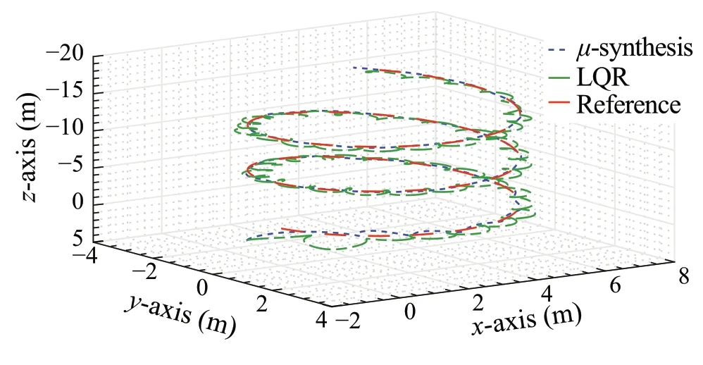
Fig.21 Trajectory tracking position three-dimensional plot with worstcase gain parameters
For this simulation scenario, the same trajectory and conditions are maintained. However, the quad-rotor’s inertial model parameters are modified to the parameters that lead to the worst-case H∞gain, which should result in the worstμ-synthesis performance. The parameters are given bym= 0.7kg,Ix=0.0044kg·m2,Iy= 0.0036kg·m2,Iz= 0.0088 kg·m2.Note that the mass variable has been modified to be less by 30% than the nominal value, which is out of the design range to test the proposed approach’s robustness against parameter variation.
Since all other conditions, except for the parameters,are kept the same. The trajectory tracking results can be compared to the simulation results of Sect.4.4. The threedimensional trajectory tracking is shown in Fig.21. As can be seen from the results,both theμ-synthesis controller and the LQR start the trajectory with oscillatory response.However, theμ-synthesis converges to the reference trajectory rapidly compared to LQR.The Euclidean distance RMSE of theμ-synthesis controller is 0.2m, which is similar to the value achieved for the nominal parameters model.While for the LQR controller,the Euclidean distance RMSE increased significantly after parameter variation with a value of 0.39m.
According to the position tracking error plots shown in Fig.22, theμ-synthesis shows more robust performance,as the response after parameter variation is similar to the response with nominal parameters.However,the LQR controller is affected negatively by changing the parameters.
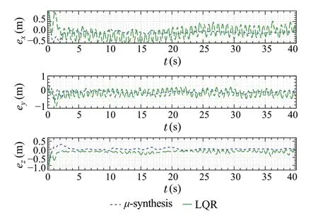
Fig.22 Position tracking error signals with worst-case gain parameters
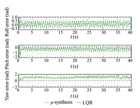
Fig.23 Attitude tracking error signals with worst-case gain parameters
As for the attitude tracking error shown in Fig.23,it can be observed that theμ-synthesis starts with oscillatory response at the beginning of the simulation. However, it converges rapidly.While the LQR performance is not acceptable.The RMSE for the roll, pitch, and yaw angles when using theμ-synthesis controller are 0.09rad,0.075rad,and 0.013rad.While the RMSE for the roll, pitch, and yaw angles when using the LQR controller are 0.3rad, 0.33rad, and 1.1rad.This shows that the LQR fails to handle the parameters’variation and time delays,which are handled effectively by theμ-synthesis controller.
For this test scenario, the torques produced by theμsynthesis controller about thex,y, andz-axes are shown in Fig.24. As can be observed from the figure, the peak magnitude is similar to that of the first experiment, while the maximum torque value achieved by the LQR controller reaches a peak value of 1Nm, as shown in Fig.25. Also note that theμ-synthesis starts with more oscillatory torques.However,it converges rapidly to small values.Similar to the first test case,the LQR torque value is large compared to theμ-synthesis(Figs.24,25).
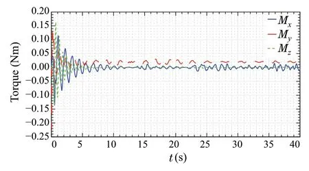
Fig. 24 Torque signals of μ-synthesis controller with worst-case parameters
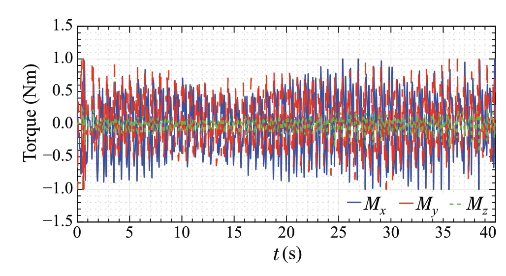
Fig.25 Torque signals of LQR controller with worst-case gain parameters
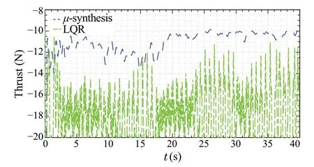
Fig.26 Thrust signals of both controllers with worst-case parameters
In addition, the thrust force produced by the proposed approach and the LQR controller are shown in Fig.26.The thrust force produced by LQR is higher as it is not capable of dealing with the uncertainties in the model and time delays.Moreover, by comparing the LQR andμ-synthesis control effort signals, it should be noted that theμ-synthesis controller produces a more feasible thrust signal compared to LQR.
4.6 Experimental setup
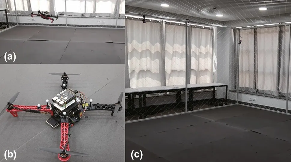
Fig.27 a The quad-rotor during the experiment.b Image of the quadrotor setup.c The CDS lab test area
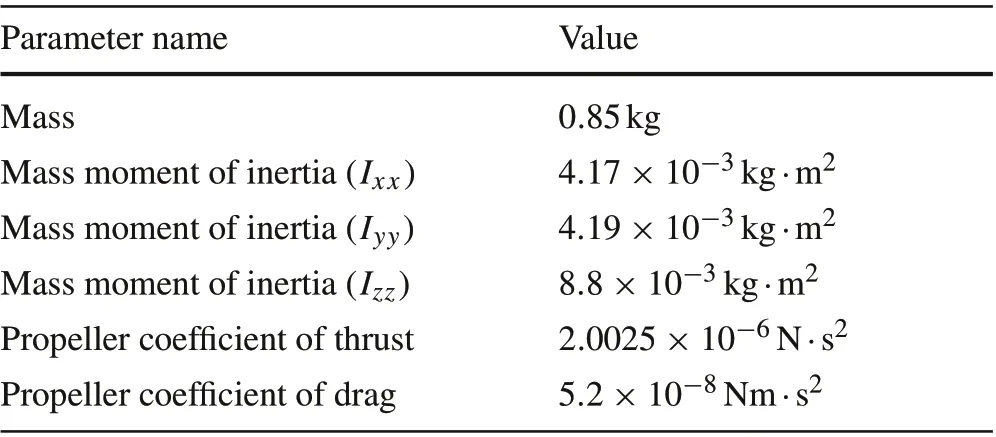
Table 5 Parameters of quad-rotor setup
To verify the practicality of the proposedμ-synthesis control approach, an experiment is performed on a real quad-rotor system, developed in the Control and Dynamical Systems(CDS)Lab at the German University in Cairo(GUC).Different images of the experimental setup are shown in Fig.27.The lab is equipped with an Optitrack motion capture system [39], which is used to provide the quad-rotor with the required attitude and position measurements over network.
The quad-rotor uses an onboard Raspberry Pi 3 computer combined with a Navio 2 hat for control law implementation.The controller is implemented using the C++programming language.The control law is calculated with a sampling frequency off= 200Hz. The average computational time of the proposed controller is 240µs, which represents only about 5% of the total available computational time. The parameters of the quad-rotor are given in Table 5.The data presented in the table is the result of multiple experiments including weight measurement, moment of inertia estimation [40], and thrust vs propeller RPM measurement by an electronic scale and a laser tachometer.
4.7 Experiment scenario
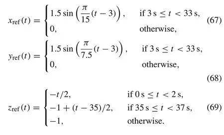
The experiment to be carried by the experimental setup consists of taking off to a height of 1 m, then performing an infinity shaped trajectory in thexy-plane, starting from the center of the infinity shape. After performing the infinity shaped trajectory, the quad-rotor lands where it took off in the first place.Thex,y,andzreferences during the infinity
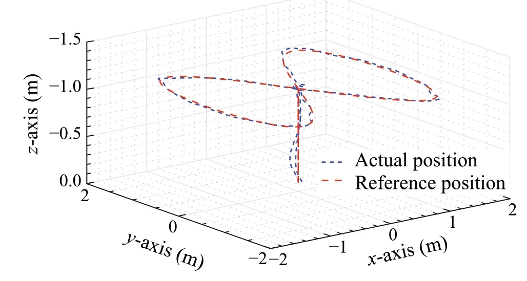
Fig.28 Three-dimensional position plot
trajectory experiment are given as follows:
4.8 Experimental results
The results of the experiment described previously are presented in this section. The three- and two-dimensional position trajectory tracking plots are shown in Figs.28 and 29,respectively.From the three-dimensional plot,it can be seen that the actual position almost overlaps the reference position with a small error.
From the two-dimensional tracking plot shown in Fig.29,itcanbeobservedthatthequad-rotorcanmaintainitsposition very close to the reference position throughout the trajectory.This validates the trajectory tracking capability of the proposed controller.
To further validate the quad-rotor’s tracking performance,the error in each axis is plotted against time, as shown in Fig.30. As can be seen from the plots, the maximum error is less than 0.2m in all the axes. It can be observed that the peak error values occur during the start and end of the infinity shaped trajectory for thexandyaxes att=3s andt= 33s,while for thez-axis,the maximum error occurred during takeoff. In addition, the RMSE is calculated to be 0.029m, 0.0445m, and 0.038m for thex,y, andzaxes,respectively.
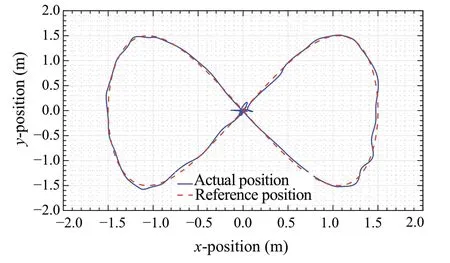
Fig.29 xy-Plane position plot
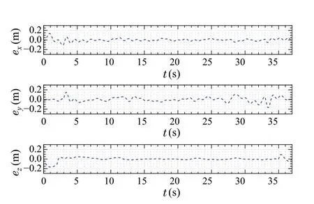
Fig.30 Error plots for the position axes
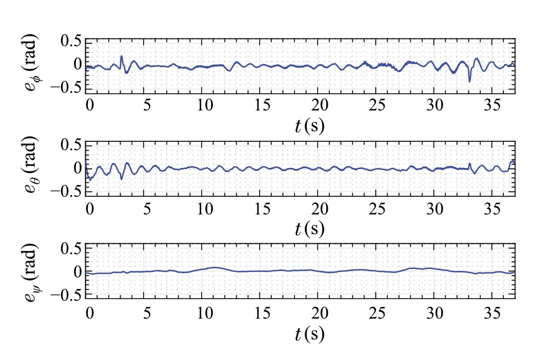
Fig.31 Error plots for the attitude angles
The error plots for the attitude angles are shown in Fig.31.The RMSE is calculated to be 0.054rad, 0.051rad, and 0.03rad for the roll,pitch,and yaw angles,respectively.Similar to the position error graphs,the peak error values in the roll and pitch attitude tracking occurred during the start and end of the infinity shaped trajectory att= 3s andt= 33s.This is mainly due to the sudden change in the reference trajectory speed at these points.
5 Conclusion
This paper presents aμ-synthesis-based approach to the design of a trajectory tracking controller,which is applied on the quad-rotor system.The robust controller can reject different types of disturbances and is able to deal with uncertainties of even infinite dimension,such as time delays,effectively.The proposed approach covers a weakly nonlinear range of operation,which is reasonable for many applications,while maintaining low computational cost, since the controller is linear and fixed.The controller was tested via a realistic simulation environment and compared to an LQR controller.According to the simulations, the proposed controller has superior performance, even in the presence of time delays and disturbances. In addition, the proposed controller was tested on an experimental setup to verify its practicality.Both simulations and experiments confirm the validity of the proposedμ-synthesis-based controller for trajectory tracking while handling different types of disturbances and uncertainties.
杂志排行
Control Theory and Technology的其它文章
- Retrospect and prospect on integration of gain and phase for feedback stability analysis
- A new path planning method for bevel-tip flexible needle insertion in 3D space with multiple targets and obstacles
- Discrete-time sliding mode control with power rate exponential reaching law of a pneumatic artificial muscle system
- Bipartite consensus for nonlinear time-delay multiagent systems via time-varying gain control method
- Cooperative distributed state estimation:resilient topologies against smart spoofers
- Strong observability as a sufficient condition for non-singularity and lossless convexification in optimal control with mixed constraints
