Analysis of Magnetic Positioning for Liquid Oxygen Under Microgravity Condition
2022-02-10,*,
,*,
1. School of Civil Engineering and Geomatics, Southwest Petroleum University, Chengdu 610500, P. R. China;
2. Chair of Thermal Process Engineering, Otto von Guericke University, Magdeburg P.O. 4120, 39106, Germany
Abstract: Due to the paramagnetic property of liquid oxygen, the Kelvin force can be induced in liquid oxygen under non-uniform magnetic field. Based on the volume of fluid(VOF) model, the positioning effect of the force in liquid oxygen tanks is analyzed under various Bond numbers (Bo) and magnetic Bond numbers (Bom). The results show that the magnetic field has the effect of repositioning the liquid oxygen in the tank when the gravity field is not enough or absent. Additionally, the gas-liquid interface has a periodic fluctuation during the process due to the inhomogeneous Kelvin force distribution, and more effective suppression of fluctuation can be achieved under the condition of a larger Bom. The new method of controlling gas-liquid interface of liquid oxygen tank under micro gravity condition is hoped to be developed in the future.
Key words:magnetic field; microgravity environment; liquid oxygen; gas-liquid interface
0 Introduction
The step of outer space exploration has never been stopped or even slowed down. Nowadays scientists and society pay great attention to the research and development of interplanetary exploration and travel. Previous lunar missions were fueled by propellants including cryogenic liquid hydrogen (LH2) and cryogenic liquid oxygen (LOX). If the spacecraft carries these cryogenic fuels in the future, fundamental issues associated with storage and transfer of cryogenic propellants must be addressed first before any of these missions become fully realizable[1].
The spacecraft has to experience a changed gravity environment on any mission between earth ground and outer space. Gravity affects many processes, such as the controlling of vapor-liquid interface within a propellant tank. In general, the location of interface of liquid and vapor is governed by the lowest achievable potential energy state within the tank. In the earth’s gravity field, density difference determines heavy phase sinking and light one floating. However, the surface tension becomes controlling mechanism for the separation of two phases with different density because liquid tends to wet walls in the microgravity conditions[2]. If the vaporliquid mixture covers the tank outlet and is sent to the engine, it may cause combustion instabilities, or even engine failure.
Up to now, various methods such as analytical, experimental, and computational studies have been performed in order to seek reliable and efficient technologies for the management of cryogenic propellants in reduced gravity environment[3-5]. Liquid acquisition devices (LAD)[6-7], which aim to increase the total surface tension force by setting specific geometries inside the tank, are used extensively. However, the method may result in the increasing of the system in weight and complexity. Others try to control liquid location by settling external thrusters out of the tank may also reduce system reliability due to the additional thrusters[4,8]. More efficient method is hoped to be developed if magnetic field is considered to be used as liquid positioning.
As LOX is a typical paramagnetic material, the Kelvin force[9]can be involved if the liquid is located in the gradient magnetic field. Bashtovoi et al.[10]found that the external magnetic field has a stabilizing effect on the jet of magnetically susceptible fluid. And Bashtovoi et al.[11]demonstrated that the free surface of paramagnetic fluid is subjected to magnetic field intensity and gradient if both gravitational and capillary forces are neglected. Rakoczy et al.[12]has successfully used the rotating magnetic field to reinforce the oxygen mass transfer. Bao’s work[13]showed that free interface of liquid oxygen can be efficiently controlled by employing external inhomogeneous magnetic field, and this non-contacting method may provide great potential for enhancing the operating efficiency of cryogenic air separation. Song et al.[14]analyzed the effects of magnet position and strength on the thermomagnetic convection of gaseous oxygen in a square enclosure under combined magnetic and gravity field. As the development of numerical calculation, the simulation research on high-intensity magnetic field may not be as expensive as experimental research. Marchetta et al.[15]gave a computational simulation of magnetic positive positioning effect on cryogenic propellant reorientation in reduced gravity environment. And Marchetta et al.[16]incorporated incompressible flow model and electromagnetic field model to predict fluid reorientation in realistic magnetic field.
Based on the volume of fluid(VOF) method, the 2-D numerical simulation of LOX free interface evolution under magnetic field was achieved. It evaluated the ability of magnetic positioning LOX under microgravity condition, and this work should be meaningful for the development of controlling free interface of LOX in the propellant tank.
1 Numerical Model Setup
The 2-D numerical calculation domain is shown in Fig.1, where the tank partially filled with LOX is placed above the permanent magnet,Wis the width of magnetic field calculation domain,His the height of magnetic field calculation domain,Wmis the width of magnet,Hmis the height of magnet,Hgis the height of tank, andDis the diameter of tank. The VOF model[17-19]is adopted to simulate the gasliquid interface evolution with and without magnetic field influence. Two phases share the same mass conservation and momentum equations, each phase is identified by the volume fraction (αi) as shown below
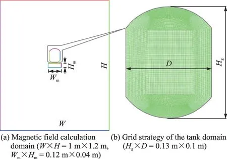
Fig.1 Geometric model and grid strategy used in this work
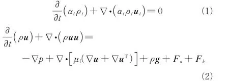
whereρis the mixture density;pthe pressure;μfthe dynamic viscosity;gthe acceleration of gravity;FσandFkare the surface tension force and the Kelvin force, respectively.
The surface tension force(Fσ) at gas-liquid interface is expressed as the form of volume force following the continuum surface force (CSF) model proposed by Brackbill et al.[20], shown as

whereσis the surface tension;αlthe liquid fraction;αgthe void fraction;ρlandρgare the liquid density and gas density, respectively; andκlandκgthe liquid phase curvature and gas phase curvature, respectively.κis the curvature computed from the divergence of unit surface normal vectorn0, shown as

The surface normal vectornis defined as the gradient ofαi, whereαiis the volume fraction ofith phase.

The Kelvin force is defined as

whereμ0is the permeability of vacuum (4π×10-7N/A2), magnetic susceptibilityχ=μr-1,μris the relative magnetic permeability. The induced magnetic field generated by liquid oxygen is small enough to be ignored. Therefore, only the magnetic field around a permanent magnet is involved. The magnetic flux densityBcan be calculated according to Maxwell equation, shown as

whereμ=μ0μrand the relevant parameters are shown in Table 1[21-22].
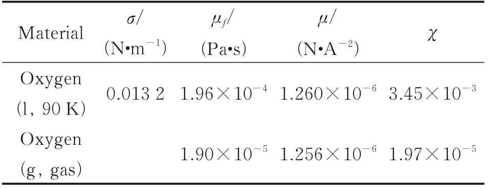
Table 1 Physical parameters of oxygen[21-22]
The Reynolds numberReis defined by

whereumis the characteristic velocity;dathe characteristic length;νthe kinematic viscosity. It is estimated that the Reynolds number is between 0 and 1 050 in this work, so the laminar flow model is selected for the calculation. The geometric reconstruction scheme is used to track the dynamics of gas-liquid interface in Fluent®. The equations above are solved implicitly, and the standard finite difference interpolation method is used to calculate the volume integral value in current time step. In addition, under the convergent condition, the second-order upwind scheme is used for momentum equation in order to improve calculation accuracy. The PRESTO method is used for discrete pressure, and the flow field is solved by mean of the SIMPLC method which is pressure-velocity coupled. The residual errors are controlled below 10-5in each iteration calculation of the controlled equations.
2 Results and Discussion
As shown in Fig.2, the grid independence test is given based on the cases with cells number of 9 629, 17 411, 27 070 and 39 839, respectively. In the test, LOX is used as working fluid in microgravity environment, the initial LOX is 0.085 m in the tank, the surface tension force between liquid and gas phase is set to 0.013 2 N/m, and the contact angle is 10°. Considering grid-independent solution and calculation capability, the case with 27 070 cells is better to be adopted in this simulation.
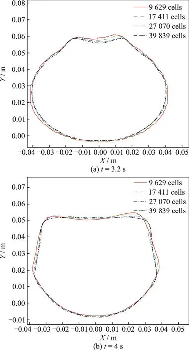
Fig.2 Grid test of the LOX free surface shape
If the gravity is absent, the contact angle, i.e., the wall wettability, determines the behavior of the liquid oxygen and the evolution process of the free interface. In the case of hydrophilic wall, the liquid has the trend of expanding along the surface. The surface tension force inY-axis direction drags fluid nearby the wall along the surface upwards. Due to fluid continuity, the force transmission in liquid phase results in the changing of free interface. If no other means is timely adopted to control the trend, the liquid phase may cover all the wall and gas oxygen is squeezed into the central zone, as shown in Fig.3. The numerical simulation of interface evolution is consistent with the result in Ref.[23]. Furthermore, the simulation prediction of FC-72 free surface evolution has been compared with the same microgravity experiment results[24], as shown in Fig.4, where the height of free interface edgeHiis defined as the distance from free interface top to the bottom of tank.
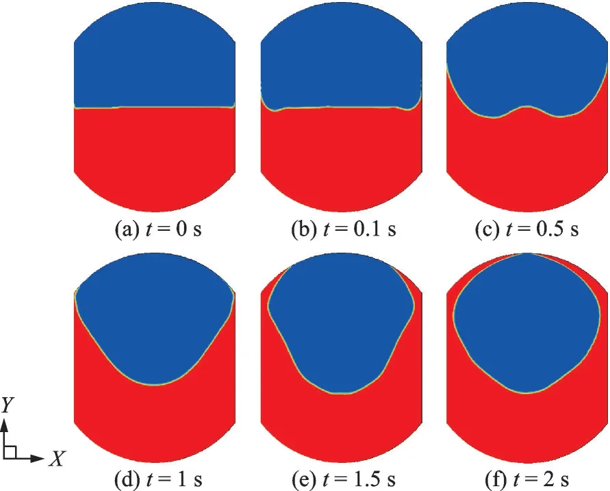
Fig.3 Free interface evolution of liquid oxygen without magnetic field and gravity
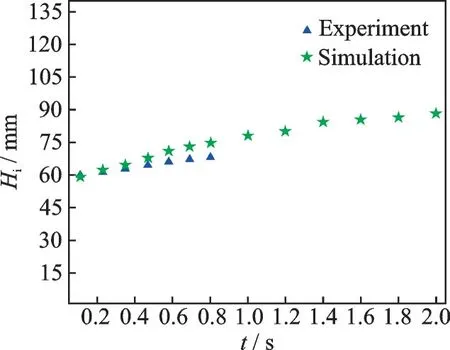
Fig.4 Model validation with experimental results[24]
If there is an external force field, such as the gravity or the Kelvin force, it may completely change the interface evolution process and the final distribution of two phases in the tank. In this work, the magnet magnetized along theY-axis direction is placed below the propellant tank. As shown in Fig.5, the magnetic potential and magnetic flux density in space are calculated respectively when magnetic flux density is set to 0.6 T at the top and bottom surfaces. At the same time, the square of magnetic flux density within the tank can be obtained as shown in Fig.6. It is assumed that no magnetic flux passes through the calculation boundary. The magnetic field within the tank is symmetrically distributed along the center line, and it is greater at the bottom than the upper space. The Kelvin force is involved where the magnetic field is non homogeneous, but the magnitude in the two phases varies greatly due to the obvious difference of magnetic susceptibility in gas and liquid oxygen. As shown in Figs.7(a, b), the force below the liquid is significantly greater than that above the interface. The force reaches to maximum nearby the bottom where gradient of magnetic field is the largest. Here the magnetic Bond number (Bom) is defined as
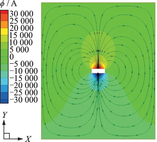
Fig.5 Magnetic potential (φ,contour) and magnetic flux density (B, arrow lines) around permanent magnet

Fig.6 Square of magnetic flux density in the tank (|B|2, contours), and magnetic flux orientation (B, arrow lines)

The calculated Bomalong the interface is shown in Fig.7(c).

Fig.7 Magnitude of Kelvin force in tank and the magnetic Bond number at the interface
Initially, the tank is partially filled with liquid oxygen,hLOX=0.085 m (y=0.02 m), and the interface is motionless. If the magnetic field gradient (∇B2) is homogeneous, in other words, the Kelvin force within the liquid oxygen phase is uniform, the interface evolution is the same with the case of gravity. As shown in Fig.8, the interface has not been found any form of fluctuation and stays motionless all the way. Obviously, the repositioning of magnetic field for liquid oxygen is effective, and the liquid is held at the lower half of the tank. Although the surface tension works at the wall all the time, it will never drag the liquid along the wall far away.
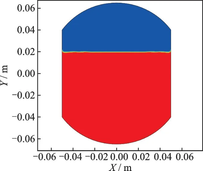
Fig.8 Form of the interface evolution at last under the case of ∇B2=10 T2/m
If the magnet is placed below the tank, the gradient magnet field is introduced within the domain, and the Kelvin force is involved. The force distribution is non-equilibrium within the tank as shown in Fig.7. The free interface is not motionless any more, and it shows periodic fluctuation as shown in Fig.9. The velocity of the points at the position ofx=0 m andy=0.02 m is recorded as the time flow.
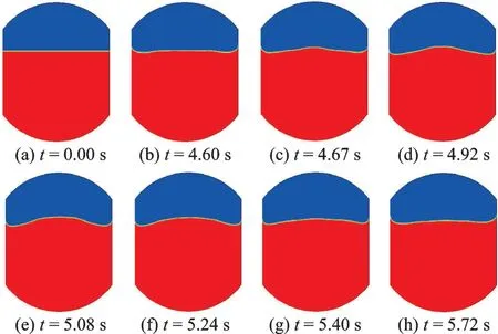
Fig.9 Periodic fluctuation of the gas-liquid interface under gradient magnetic field
The change of liquid contact angle at the wall determines the magnitude of the surface tension force inY-axis direction. If the liquid contact angle is below 90°, the surface tension force at the wall plays the role of stretching the liquid creep along the wall upwards. Although the surface tension along the wall is changed in various contact angles, its magnitude is much smaller than the Kelvin force, and the mean Bomis about 1 851 at the gas-liquid interface. The change of angle by no means alters the fluctuation of interface in the case of 1.2 T field, as shown in Figs.10 and 11. The fluctuation period and maximum amplitude have not been changed obviously.
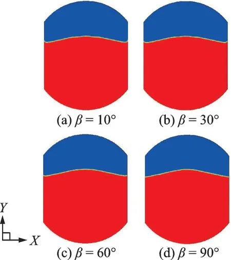
Fig.10 Transient form of the interface with various contact angles from 10° to 90° at the time point of 1.88 s
From the results shown in Fig.12, it is found that a larger magnetic Bond number leads to smaller period of velocity fluctuation at the monitored site. The obvious change of the maximum velocity is not found, so it can be concluded that the corresponding amplitude has been decreased. As shown in Fig.13, as the magnetic field increases, the wave has been put down slightly.
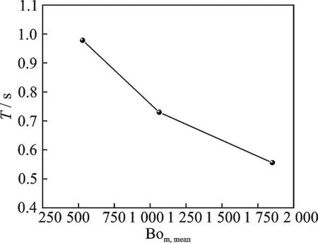
Fig.12 Period of velocity fluctuation at the monitored point (x=0 m, y=0.02 m) vs. Bom,mean (g=0, contact angle is set to be 10°)
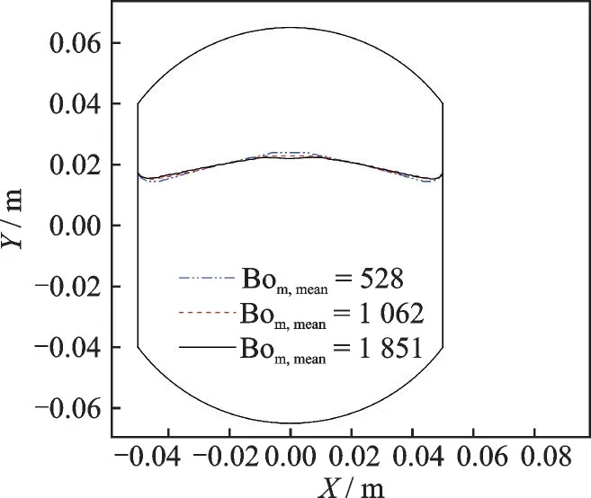
Fig.13 Maximum amplitudes of interface fluctuation with various Bom,mean
As shown in Fig.14, as Bond number increases, the fluctuation period becomes shorter, and the maximum velocity is about 0.02 m/s which has not been obvious changed. The periodic fluctuation is the result of the non-homogeneous force distribution, and the force refers to the Kelvin force, gravity force and the surface tension force. As Bo increases, the gravity force is dominated, the unevenness of the force filed involved by the Kelvin force within the tank is weaken, and the positioning effect of the force fields become more obvious. Therefore, the fluctuation decreases as Bo increases, as shown in Fig.15, the relationship can be expressed as
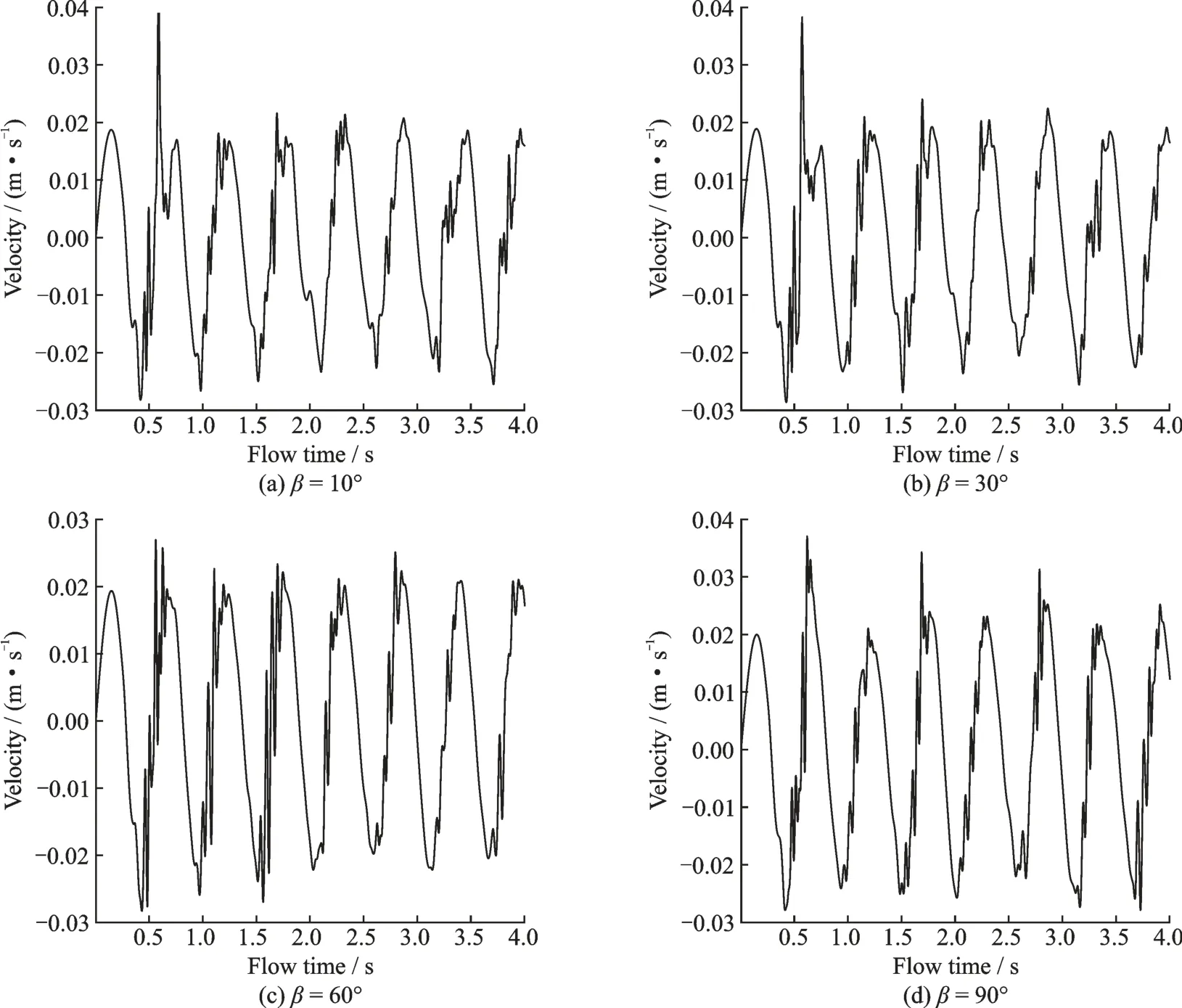
Fig.11 Velocity fluctuation of the monitored point (x=0 m, y=0.02 m) with various contact angles
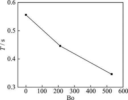
Fig.14 Period of the velocity fluctuation at the monitored point (x=0 m, y=0.02 m) vs. Bo under 1.2 T magnetic field

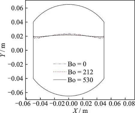
Fig.15 Maximum amplitudes of interface fluctuation under various Bond numbers
where Bom,maxis the maximum Bomat a certain time in the tank; Bom,minthe minimum Bomat a certain time in the tank; and Bom,meanthe mean Bomat a certain time in the tank. The mechanism of magnetic field affecting the free interface fluctuation is interesting. As shown in Fig.16, the Kelvin force inXaxis direction is left-right opposite, which leads to the interface bend towards the upside, it seems like the bow is bent. But the bulge will not keep going up, as the interface is curved, a larger amount of liquid within the domain of bulge, which subjects to a greater Kelvin force inY-axis direction, gives rise to the increasing potential energy. The fluctuation will fall back after it reaches to the highest point. It is obvious that larger magnetic field induces greater Kelvin force in bothXandYdirections at the same time. The greater force causes the liquid to swell at a faster speed until it reaches the highest point, and the force inY-axis direction makes the potential energy accumulated more rapidly at the same time. So as the magnetic Bond number increases, the fluctuation period becomes smaller and the maximum amplitude turns to be decreased. Likewise, under the same magnetic field, as the Bond number increases, the force inY-axis direction becomes greater all the time, i.e. sum of the Kelvin and gravity forces, but the force inX-axis direction is not changed, so the amplitude turns to be smaller as well.
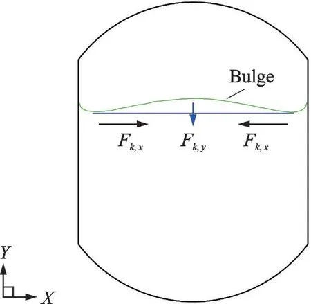
Fig.16 Mechanism of Kelvin force influence on free interface fluctuation
If the velocity is monitored over a longer time span, it is found that the fluctuation is gradually weakening, the velocity at the monitored point tends to be zero in the end, and the upwelling interface is formed at last, as shown in Figs.17 and 18.
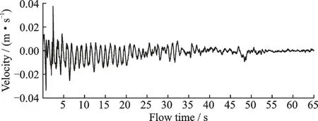
Fig.17 Velocity fluctuation of the monitored point (x=0 m, y=0.02 m) over a time span of 65 s

Fig.18 Final motionless interface under magnetic field
3 Conclusions
Based on the above simulation and analysis, it is shown that the magnetic field has the effect of repositioning and controlling the LOX under microgravity conditions. The liquid interface undergoes a process of periodic fluctuation, but the fluctuation will gradually attenuate and finally form a convex liquid surface. The fluctuation is subject to the magnetic Bond number Bomand the Bond number Bo. Larger Bomand Bo are more effective in repositioning liquid oxygen and restraining interface fluctuation.
杂志排行
Transactions of Nanjing University of Aeronautics and Astronautics的其它文章
- Effects of Lobe Peak-to-Trough Width Ratio on Mixing and Combustion Performance in ATR Combustors
- Numerical Investigation of an Active Jet Control Method for Hypersonic Inlet Restart
- Flow and Leakage Characteristics in Sealing Chamber of a Variable Geometry Hypersonic Inlet
- Path Planning for Lunar Surface Robots Based on Improved Ant Colony Algorithm
- Iterative Identification of Robot Dynamic Parameters Based on Logistic Function
- Adaptive Tracking Control for Diffractive Film Based on Nonlinear Sliding Mode
