Numerical Investigation of an Active Jet Control Method for Hypersonic Inlet Restart
2022-02-10,
,
1. Institute of Applied Physics and Computational Mathematics, Beijing 100094, P.R. China; 2. Key Laboratory of High-Temperature Gas Dynamics, Institute of Mechanics, Chinese Academy of Sciences, Beijing 100190, P.R. China;3. School of Engineering Science, University of Chinese Academy of Sciences, Beijing 100049, P.R. China
Abstract: A flow control method based on an active jet is developed to restart hypersonic inlets. The dynamic restarting process is numerically reproduced by unsteady Reynolds averaged Navier-Stokes(RANS) modeling to verify the effectiveness and reveal the influence of jet conditions. The active jet improves the inlet unstart status by drawing the high-pressure separation bubble from the internal compression duct and performing a full expansion to alleviate the adverse pressure gradient. Moreover, the favorable pressure gradient in the inlet caused by jet expansion allows for a successful restart after turning off the jet. The influence of the jet momentum ratio is then analyzed to guide the design of the active jet control method and choose the proper momentum ratios. A low jet momentum does not eliminate the high-pressure separation bubble, whereas an excessive jet momentum causes severe momentum loss due to the induced shock. The general rule in restarting the inlet using an active jet is to allow a full jet expansion downstream of the jet slot while avoiding excessive momentum loss upstream and preventing the thick low-speed layer.
Key words:hypersonic inlet; unstart; restart; active jet; flow control
0 Introduction
Hypersonic inlets are vital components for scramjet engines in high-speed air-breathing vehicles. In the unstart hypersonic inlet, the interaction caused by the strong shock wave/boundary layer leads to a considerable decrease in the compression efficiency and flow-capture capability, as well as a higher aerodynamic drag[1], which seriously reduces the flight quality of the aircraft and even leads to flight failure. Thus, good starting capabilities are crucial for the stable and efficient operation of hypersonic vehicles.
Over the past decades, numerous studies have been conducted on the start performance of hypersonic inlets, including the unstart mechanism[2-3], unstart detection[4-5], and flow control[6-9]. For better flight performance, various control methods have been developed to prevent or delay its unstart, e.g., bleeding[10], vortex generators[11-12], boundary layer blowing[13], and energy addition[14]. The general idea behind these methods is to either remove low momentum flow away from the wall or increase the boundary layer’s momentum.
In addition to suppressing unstart, improving the restart capability of hypersonic inlets is also an important issue. The self-start performance of fixedgeometry inlets can be characterized by the self-start limit theories[15-16]. For the inlet with a weak selfstart ability, variable geometry and suction devices are commonly used to assist in restarting. Falempin et al.[17]adapted the translating cowl to vary the contraction ratio in the Mach number ranging from 2 to 8. Dalle et al.[18]used both moving and rotating cowl to adjust the contraction ratio and found that the variable-geometry inlet performs better in the wide Mach range. Teng and Yuan[19]implemented a variable-geometry cowl sidewall and effectively restarted the inlet from an unstart status. Liu et al.[20]dynamically simulated the rotating process of an inlet cowl and also successfully restarted the inlet. The variable geometry method is effective by adapting the contraction ratio with the operating condition, but it significantly increases the structure weight and control complexity and brings sealing problems[21]. An alternative method to assist the inlet restart is gas bleeding through a porthole on the inlet sidewall. Häberle and Gülhan[22]effectively controlled the lip-shock-induced separation in hypersonic inlets at Mach 6 with a mass discharge ratio of 5.5%. Yuan and Liang[23]decreased the self-starting Mach number from 4.2 to 3.4, while investigating the influence of suction position. Similar inlet restart applications of the bleeding method also have been conducted by Chang et al[24]. However, the main drawback of the bleeding method is that it may cause a significant portion of mass loss.
Active jet is a vital control technology in subsonic and supersonic flow. It has been universally used to reduce drag[25], control flow separation[26], improve flow distortion[27-29], and suppress shock oscillations[30]. The method directs the flow by introducing mass and energy into the mainstream. However, due to the existing separation region and severe adverse pressure gradient within the inlet, there have been more significant challenges for the active jet to restart the inlet, and the reports on this issue are sparse. When imposing an active jet, Van Wie et al.[31]experimentally studied the influences of steady fluid injection on unstart and restart in the supersonic inlet and described the potential mechanism. However, whether the inlet start can be sustained after turning off the active jet was not investigated. Subsequently, You[32]experimentally achieved the restart in the supersonic inlet using the active jet. He also numerically conducted detailed assessments, pointing out that alleviating the throat choking in virtue of the flow spillage caused by the jet is the key to restarting the inlet. Till now, the effectiveness of the active jet method has been validated in supersonic inlets with relatively low Mach numbers, providing the theoretical support for the auxiliary application of restarting high-speed inlets. Nevertheless, as internal contraction ratios increase, the flow separation inside the internal compression duct of the hypersonic inlet worsens, resulting in a more significant blockage to the incoming flow and, accordingly, a more difficult inlet restart. To the authors’ best knowledge, rare studies have been reported to successfully apply the active jet method to restart the hypersonic inlet.
Based on these contents, this study explores the effectiveness and feasibility of the active jet method in restarting hypersonic inlets. Firstly, the dynamic restarting process when imposing an active jet was wholly reproduced by unsteady Reynolds averaged Navier-Stokes (RANS) modeling, revealing the key mechanisms in hypersonic inlet restart using an active jet. The impact of the jet momentum ratio was then examined further in this study. Finally, the general rule was summarized to provide guidelines for the design of the active jet method for restarting hypersonic inlets.
1 Physical Models and Numerical Methods
1.1 Governing equations
The three-dimensional compressible Navier-Stokes equations (NSEs) are solved for a set of conservative variables
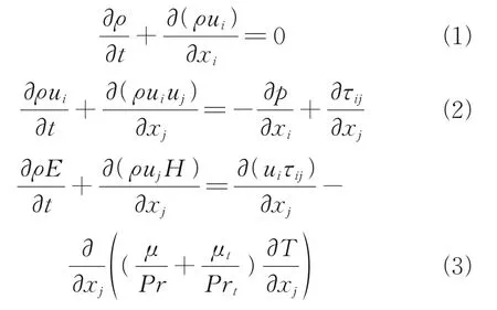
wheretdenotes the time,xithe Cartesian coordinate in the directioni,ρthe density,Tthe temperature,uithe velocity component inxidirection (spatial dimensioni= 1, 2, 3),pthe pressure, andτijthe viscous stress tensor;E=e(p,T)+0.5u2iandH=h(p,T)+0.5u2iare the total internal energy and absolute enthalpy, respectively. The laminar and turbulent Prandtl numbers are assumed to be 0.72 and 0.9. The laminar dynamics viscosity coefficientμis calculated by Sutherland law, and the turbulent viscosity coefficient is computed using the turbulence model.
1.2 Turbulence model
The main purpose of this paper is to explore the effectiveness of the active jet on the inlet restart, rather than the elaborate simulation of complex flows. Therefore, the more computationally-efficient RANS approach is applied in the present study. The two-equation shear stress transport (SST) turbulence model, developed by Menter[33]is adopted in the present paper to solve the turbulent fluctuations. The two transport equations ofk-ωSST model are described below
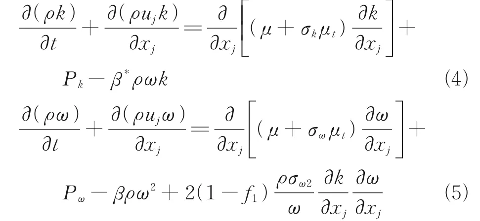
wherePkandPωare the production terms ofkandωequations, written as
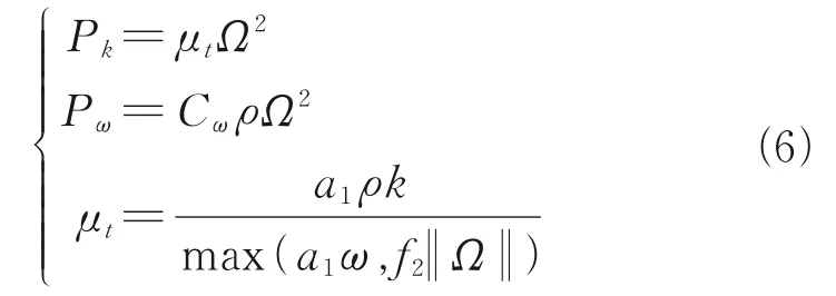
whereΩis the magnitude of vorticity. A detailed description of the other model parameters can be found in Ref.[33].
1.3 Solver and numerical method
The governing equations are solved by a n inhouse developed finite-volume compressible RANS solver, which is extended from the open-source CFD package SU2[34]. In the present simulations, the nonlinear inviscid convective fluxes are evaluated using the Roe flux-difference scheme[35]. A second-order spatial accuracy in reconstructing primitive convective fluxes at faces is achieved by the monotone upstream-centered schemes for the conservation laws (MUSCL) method[36]with the minmod limiter. Temporal integration is advanced by the implicit lower-upper symmetric Gauss-Seidel (LU-SGS) scheme[37]. Dual time step method[38]with LU-SGS scheme is employed in unsteady modelings. For the second-order temporal accuracy, the maximum density residual decreases about three orders of magnitude in the inner loop. A fixed physical time-step of 1.6×10⁻⁷s is employed in the timemarching process.
1.4 Experimental case
Fig.1 shows the examined two-dimensional hypersonic inlet configured with two compression ramps, with the inclination angles of 9° and 14° to the freestream flow direction, respectively. An isolator is immediately behind the throat with a constant cross-section of 10 mm in height and 115 mm in length. Fig.2 schematically illustrates the computational grid and boundary conditions, which are set up by referring to Ref.[9]. The computational domain is extended by an additional expansion channel. A multi-block structured grid is utilized to mesh the whole domain. The mesh is clustered in the second ramp, internal compression duct and isolator to better capture the flow structures, while the coarser mesh is used in the far field to reduce the computational cost. To take into account the three-dimensioanl turbulence effect, the span-wise length is set to 10 mm, with the periodic boundary conditions applied on the two lateral sides.
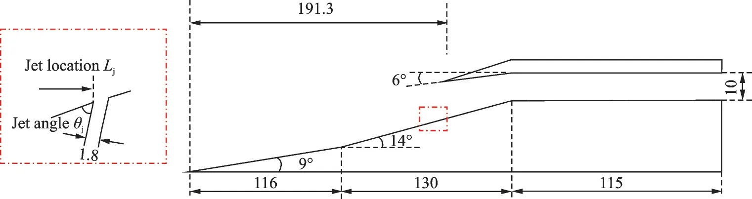
Fig.1 Two-dimensional hypersonic inlet configuration
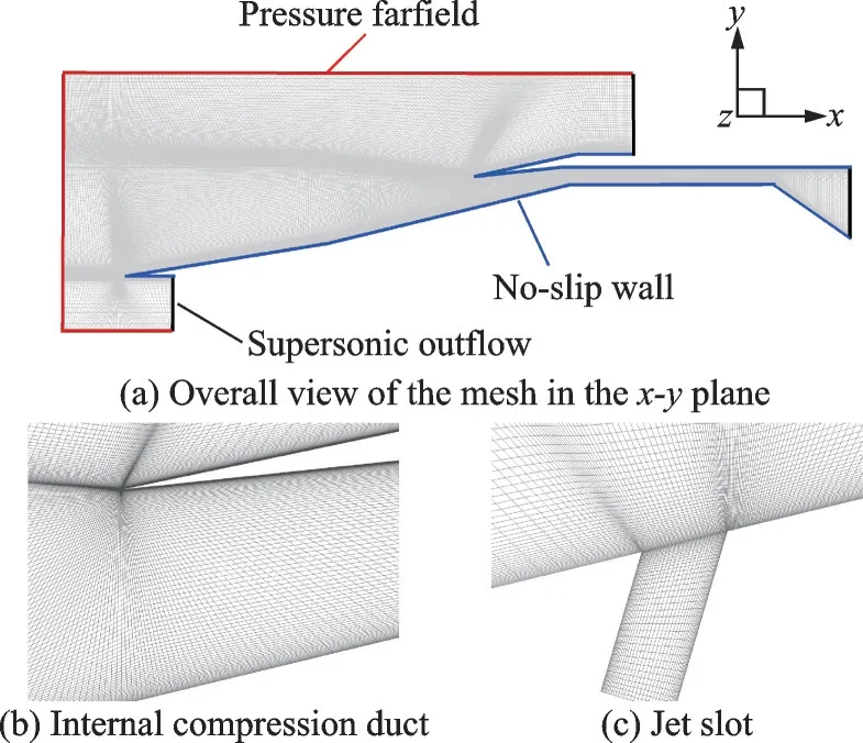
Fig.2 Schematics of the computational domain and boundary conditions
2 Correlations and Validations
2.1 Validation
The numerical framework is validated against the benchmark experiment of Häberle and Gülhan[39]. The model inlet was tested in a hypersonic tunnel with the flow conditions in Table 1.
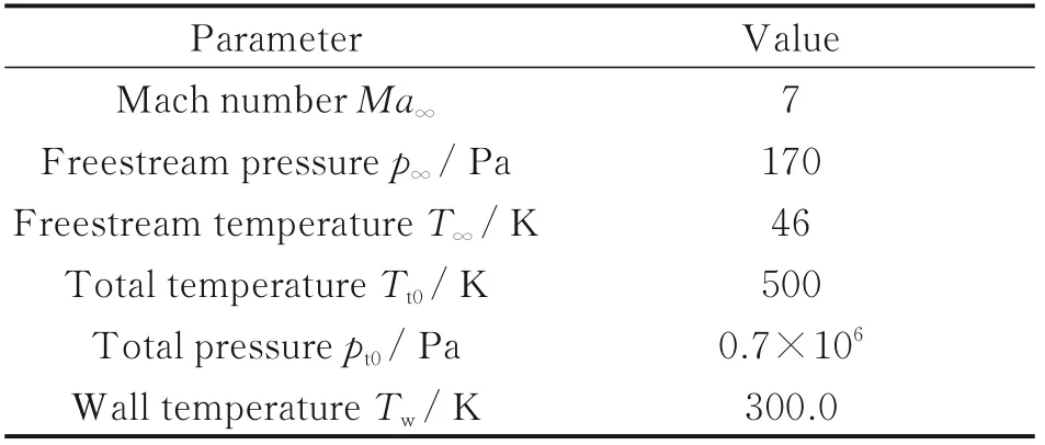
Table 1 Flow conditions for the validation case
From Fig.3, the flow structures, such as the separation bubble, separation-induced shock, and reflected shock waves inside the isolator, are well captured and agree with the experimental results[39]. Fig.4 compares the pressure coefficientCpdistributions along the upper and lower surfaces of the inlet, where overall good agreements have been obtained.
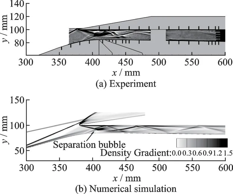
Fig.3 Schlieren images of the hypersonic inlet flow

Fig.4 Simulated and measured pressure on the upper and lower walls
2.2 Grid convergence analysis
Three meshes listed in Table 2, whereNx,Ny,Nzare the grid numbers in thex,y,zdirections andΔminis the height of the first layer grid, are used to verify the grid convergence for the model in Fig.1. The freestream has a Mach number of 3.5, a static pressure of 5 529.31 Pa, and a static temperature of 216.65 K. The main flow structures in the inlet were all predicted accurately by the three meshes. As compared in Fig.5, the slight difference of less than 0.5% between the three predictions indicates that the grid convergence has been achieved. In the subsequent modelings, the medium mesh will be used.
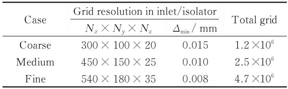
Table 2 Summary of the mesh configurations

Fig.5 Wall pressure in a start status predicted by different mesh resolutions
3 Results and Discussion
Fig.6 shows the mass flow ratioΦand total pressure recovery coefficientσpvarying with the freestream Mach number, and the performance parameters at the inlet throat are computed as
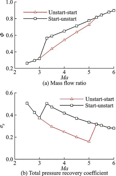
Fig.6 Throat parameters in hysteresis loops

whereis the total mass flow rate,Vthe velocity,Athe area element, andthe mass-weighted averaged variable, e.g., the Mach numberMa, static pressurep, or total pressurept.Φis calculated by/[(ρV)∞A0] , with (ρV)∞denoting the freestream mass flux andA0the inlet windward area.σpis defiend aspt/pt0, withpt0denoting the total pressure of freestream flow.
A noticeable hysteresis phenomenon, or flow memory effect[1], was observed. As the freestream Mach number increases from 2.5 to 6, the hypersonic inlet transits from unstart to start status. However, when conversely decreasing the Mach number, the transition from start to unstart status does not follow exactly the same route. The dual routes between 3.3 and 5.3 form a well-known hysteresis loop.
Fig.7 shows the start and unstart Mach contours under the freestream Mach number ofMa∞=3.5. The performance parameters at the throat are compared in Table 3. In an off-design condition, the external shock waves fall ahead of the inlet entrance. When the inlet starts, the reflected shock waves of the cowl shock form a shock train in the isolator to balance the upstream and downstream pressure. Under the unstart status, the separationinduced shock leads to flow spillage and momentum loss. Behind the aerodynamic throat, the incoming air is further receded to subsonic.
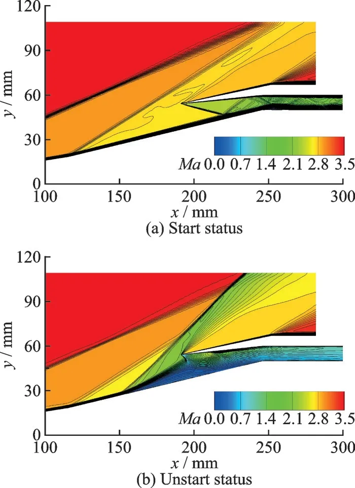
Fig.7 Mach contours under start and unstart status
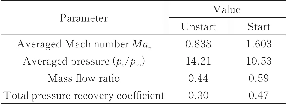
Table 3 Throat parameters at Ma∞=3.5
As shown in Fig.8, the separation-induced and lip shock combination produces a sizeable adverse pressure gradient, which is crucial to maintaining unstart status. To dispel the separation bubble, a higher flow velocity is usually needed to overcome the adverse pressure. However, it would lead to a relatively high self-starting Mach number. For better starting capabilities, it is desired to restart the inlet without the demanding requirement for freestream conditions, e.g., using the active jet method as introduced below.

Fig.8 Flow structures of unstart status
3.1 Analysis for restart process
In this section, the effect of the active jet on restarting the inlet from an unstart status is examined. The freestream and jet parameters are summarized in Table 4. And the jet momentum ratio (J=ρju2j/ρ∞u2∞, with subscript jdenoting the jet exit conditions and ∞ the freestream conditions) is set to 7.37. The main flow structures are briefly illustrated in Fig.9 for a successful restarting case when bearing an active jet.
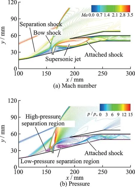
Fig.9 Flow structures with active jet

Table 4 Summary of freestream and jet parameters
The jet issued from a slot bends into the internal compression duct and then quickly expands to be supersonic flow. Due to insufficient space and residence time, the expansion is not fully expanded. However, compared with the case without an active jet, the high-pressure separation bubble almost vanishes downstream of the jet, and the adverse pressure is remarkably alleviated. After turning off the active jet, the inlet successfully restarts and maintains a started status.
To gain a deep insight into the key flow dynamics, the transient restarting process when applying an active jet is numerically reproduced in Fig.10. At Δt= 0.08 ms, the high-speed jet acts as an aerodynamic obstacle on the lower wall, blocking the freestream air. A high-pressure separation bubble and its induced shock emerge upstream of the jet. Meanwhile, the bow shock induced by the jet results in a strong flow spillage and a significant reduction in the flow velocity. At Δt= 0.26 ms, the jet strengthens the separations in both the upstream and the downstream of the slot. The high-pressure separation bubble extends further to a far upstream of the jet. The pressure in the isolator significantly reduces, and the jet penetration depth increases. The separation bubble grows continuously and nearly entirely blocks the inlet at Δt= 0.60 ms. The pressure behind the jet decreases further. At Δt=1.12 ms, the jet is bent by the high-momentum freestream towards the inlet and expands in the internal compression duct, which narrows the separation bubble and alleviates the adverse pressure gradient. At Δt=1.79 ms, the low-pressure separation bubble downstream of the jet shrinks considerably, and most of the jet flow enters the inlet. A large lowpressure region is formed behind the jet when reaching steady due to the entrainment effect. The adverse pressure gradient within the inlet has been effectively alleviated and replaced by a high-pressure separation region upstream.
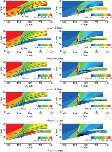
Fig.10 Evolution of Mach and pressure contours bearing an active jet
The flow evolution after turning off the active jet is shown in Fig.11. The separation bubble shrinks to the jet root and will vanish gradually, and a bow shock moves to the entrance of the internal compression duct, as seen in Fig.11(a). However, from Fig.11(b), the blocking of the high-pressure separation bubble results in a thicker low-momentum boundary layer, which lasts for a long time before its disappearance and is unfavorable for restart. During the restart process, the shock/boundary interaction produces a local high-pressure region and may even induce new separation, as shown in Fig.11(c). With the swallowing of the shock train by the internal compression duct, the supersonic incoming flow fully enters the inlet and inhibits the growth of the separation bubble. The final stable flow in Fig.11(d) indicates a start status. Thus, the start status can sustain even after the removal of the active jet. As seen, the general principle of the active jet method is to draw the high-pressure separation bubble from the internal compression duct and then inhibit the reformulation of large separation region.

Fig.11 Evolution of Mach contours after turning off the active jet
3.2 Influence of jet momentum ratio
In this section, jet momentum ratios ranging from 3.61 to 12.64 were numerically tested. Fig.12 shows the averaged Mach number and pressure at the throat under different jet momentum ratios when the flow reaches stable. The jet momentum ratios of 5.97, 7.37, and 8.91 all successfully restarted the inlet from an unstart status. The pressure at the throat decreases monotonously from the unstart state with the increased jet momentum ratio. The averaged Mach number first increases untilJ=8.91, then decreases monotonously. Except the case withJ= 3.61, all the other cases reach supersonic at the throat.
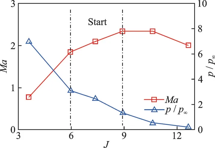
Fig.12 Throat parameters under different jet momentum ratios
Fig.13 compares the Mach contours under different jet momentum ratios. As the jet momentum ratio increases, a more remarkable increase in the jet penetration depth can be observed. AtJ= 3.61, the active jet enlarges the separation bubble and aggravates the unstart. When the jet momentum ratio reaches 4.72, the inlet flow oscillates between the start and unstart statuses. Between the jet momentum ratio of 5.97 and 8.91, the jet fully blocks the incoming flow, and the jet flow nearly entirely enters the inlet, where the expansion of the jet wake effectively alleviates the adverse pressure gradient in the internal compression duct and results in a successful inlet restart after removing the jet. With the further increase of the jet momentum ratio to 10.61, the too higher jet penetration depth causes flow spillage, and it also induces giant separation bubbles close to the jet root and considerably strengthens the induced shock. In consequence, the hypersonic inlet fails to restart after the jet is turned off, as shown in Fig.14.
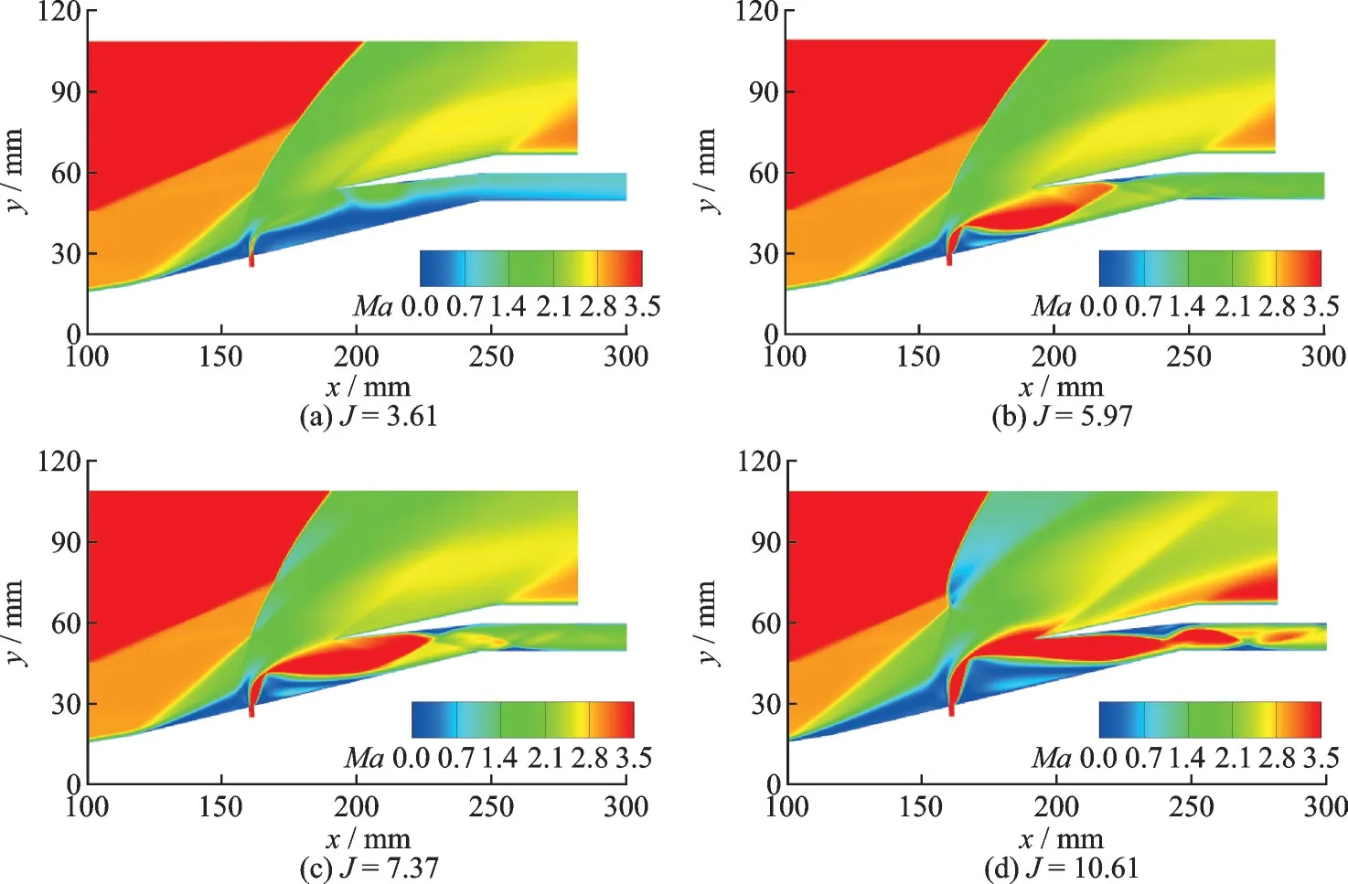
Fig.13 Mach contours under different jet momentum ratios
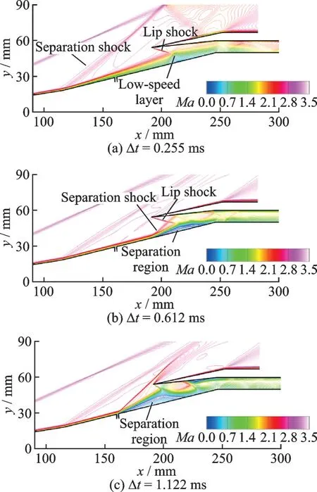
Fig.14 Evolution of flow structures at J=10.61 after turning off the jet
After turning off the jet, the separation bubble on the lower wall thickens the boundary layer and reduces the effective flow-through area, while the induced shock wave reduces the incoming flow momentum. The growth of the new separation bubble retrogresses the inlet to the unstart status. The above analysis indicates that the key to restarting the inlet is to reduce the adverse pressure gradient and prevent severely thickening the boundary layer.
4 Conclusions
This study presented an active flow control method based on a high-pressure jet to restart the hypersonic inlet. The dynamic restarting process was numerically reproduced to elaborate the restarting mechanism. The inlet restarting capability of the proposed active jet control method was thoroughly validated, and the restarting principle was revealed. The inlet unstart is usually caused by the strong adverse pressure gradient and the reduction in the effective flow-through area by the boundary-layer blockage effect. The high-momentum jet wake flow blocks the incoming flow and alleviates the congestion downstream. And a full expansion within the internal compression duct not only overcomes the adverse pressure gradient but also eliminates the highpressure separation bubble. The dynamic flow evolution of a successful restart follows two main steps: Firstly, the high-pressure separation bubble is transferred upstream, then the adverse pressure gradient in the internal compression duct is alleviated by the jet expansion; secondly, the freestream enters after turning off the jet and reestablishes the start flow field from a favorable pressure gradient.
The influence of the jet momentum ratio was analyzed to guide the design of the active jet control method. The inlet can be restarted at a moderate jet momentum ratio between 5.97 and 8.91; the lower jet momentum can not effectively eliminate the adverse pressure gradient, while a higher jet momentum causes severe spillage and loss of flow momentum. When restarting the inlet with an active jet, the general rule is to allow a full jet expansion within the inlet, which provides flushing and sealing effects while avoiding excessive momentum loss upstream and preventing the thick low-speed layer after turning off the active jet. This rule should be followed when optimizing jet configurations.
杂志排行

Transactions of Nanjing University of Aeronautics and Astronautics的其它文章
- Analysis of Magnetic Positioning for Liquid Oxygen Under Microgravity Condition
- Mechanical Analysis and Numerical Simulation for New Type of Dynamic Control Devices
- Structural Dynamic Optimization for Flexible Beam of Helicopter Rotor Based on GA
- Aircraft Optimal Separation Allocation Based on Global Optimization Algorithm
- Adaptive Tracking Control for Diffractive Film Based on Nonlinear Sliding Mode
- Iterative Identification of Robot Dynamic Parameters Based on Logistic Function