Some aspects affecting the response of RC compartment structures subjected to internal blast loads
2022-01-21OsmanRamadanGalalElSherbinyandAhmedKhalil
Osman M. O. Ramadan, M. Galal El Sherbiny and Ahmed M. Khalil
1. Faculty of Engineering, Cairo University, Cairo 12411, Egypt
2. Higher Technological Institute (HTI) at 10th of Ramadan City, Sharqia 13658, Egypt
3. Structural Engineering and Construction Management Department, Faculty of Engineering & Technology, Future University in Egypt - FUE, Cairo 16383, Egypt
Abstract: Protective compartments are typically used to protect some specific structures from internal explosions, such as industrial buildings that contain devices that may explode in certain circumstances. This research investigates how the response of reinforced concrete (RC) compartment structures subjected to internal blast loads are affected by the following aspects: introduction of material nonlinearity in the analysis, reinforcement ratio, and aspect ratio of the compartment. To achieve this goal, a calibrated and sophisticated FE numerical model is introduced, and a parametric study for the intended aspects is carried out. A discussion of the results and conclusions are offered, which show the role of each aspect in the dynamic performance of the compartment structures. The main conclusions are as follows: introduction of material nonlinearity in this type of analysis and for these structures is very important and significant in obtaining accurate outputs that are similar to actual behavior; the reinforcement ratio has a significant effect on the response and its effect varies depending on the thickness of the compartment; in general, increasing the reinforcement ratio enhances the behavior and reduces the stresses in the compartment; and the aspect ratio of the compartment does not show a clear pattern on the response of such structures under internal blast loads.
Keywords: blast loads; protective structures; nonlinear analysis; explicit dynamic analysis
1 Introduction
In recent years, the threat s of blast loads have increased throughout the world. Blast loads result from explosions, which can be intentional such as in a terrorist attack, or accidental such as an explosion of a device due to an error or mistake in operation. The explosion can be an internal explosion confined by the structure or an external explosion that occurs outside the structure;the response of the structure is different in each case.The response of an RC slab subjected to blast load was investigated experimentally and numerically by Kristoffersenet al. (2018). The response of RC slabs repaired with CFRP was studied (Konget al., 2018).Experimental testing for various configurations of RC slab has been carried out by many researchers (Foglar and Kovar, 2013; Tabatabaeiet al., 2013; Pantelideset al., 2014; Thiagarajanet al., 2015). The performance of ultra-high performance reinforced concrete was studied experimentally and analytically under the effect of blast load (Wuet al., 2009; Astarlioglu and Krauthammer,2014; Aoudeet al., 2016; Maoet al., 2015).
One of the most interesting features observed when concrete structures were subjected to blast load was the strain rate effect. This occurred when the RC structure was subjected to rapid dynamic load such as a blast load where the load increases rapidly to its peak in a very short time, then starts to fall in the negative phase also in a short period, and then vanishes. This type of dynamic load causes the strain of the material to change rapidly over time and consequently, significantly increases the material strength as in the case of quasi static loads,depending on the strain change rate. This phenomena is called the strain rate effect and has been studied by many researchers (Bischoff and Perry, 1991; Groteet al., 2001;Li and Meng, 2003; Cotsovos and Pavlović, 2008; Lu and Li, 2011; Chenet al., 2015). It has been taken into consideration in the nonlinear material model presented herein.
Some researchers have focused on the study of building columns and bridge piers subjected to blast loads with the aim to prevent their progressive collapse. The experimental and numerical response of concrete rectangular columns with different aspect ratios under contact explosion from different explosive charges was studied and the residual axial capacity of the damaged specimens was calculated by Duaet al.(2019). The behavior of circular RC columns subjected to an underwater explosion by considering the effect of the charge weight, standoff distance, and detonation depth was studied by Zhuanget al. (2019). The effect of the column cross section (square and circular) on its response under contact and close range explosions in air and underwater was numerically studied by Yanget al. (2019). In addition, they investigated methods to increase blast performance, such as longitudinal,transferal reinforcement, and concrete compression strengthening.
The response of steel columns with similar mechanical properties subjected to blast loads generated from two different charge weights at different standoffdistances by evaluating the damage, residual axial capacity, and displacement was investigated by Momeniet al. (2019). The performance of RC beams and columns subjected to blast loads from various charge weights and standoff distances was experimentally and numerically investigated by Liuet al. (2018). The performance of RC columns subjected to close range explosions induced by a double end initiation explosive cylinder was numerically and experimentally assessed by Huet al. (2018). In addition, the study focused on the influence of charge shape, diameter to length ratio,scaled distance, and detonation point. The effect of transverse reinforcement spacing on the response of reinforced columns subjected to far blast loading was studied by Kyei and Braimah (2017). They relied on experiential tests and various numerical simulations to determine the effect of charge weights, standoff distance,and axial load ratio. The residual axial capacity and damage of ultrahigh performance concrete columns subjected to different quantities of explosive charges at the same standoff distance was experimentally assessed by Liet al. (2017). An experimental full-scale and numerical simulation of RC members under near field explosion was studied by Codinaet al. (2016). In recent years, most existing research has primarily concentrated on the experimental or numerical behavior of concrete filled steel tube columns under contact and close range explosion. The experimental response of ultrahigh performance cementitious composite filled steel tube columns in a circular shape under contact explosion with different TNT charge weights was studied and the residual axial capacity of the damaged columns was calculated by Wanget al. (2020). The damage mechanisms and energy absorption capacity of concrete filled double steel tube (CFDST) columns in a circular shape were experimentally and numerically studied under close range explosion considering the effect of applied axial load on the columns by Liet al. (2019). However, Liet al. (2018) did not consider the effect of applied axial load in their investigation of the damage mechanism and energy absorption capacity of CFDST bridge columns under contact explosion. Liet al. (2020) considered the effect of applied axial load in ab experimental and numerical investigation of the post blast performance and residual axial capacity of CFDST under contact explosion and derived an empirical formula to predict the residual axial capacity.
Zhanget al. (2016a) studied the response of a square CFDST columns filled with ultrahigh performance concrete under close range explosion through experimental and numerical investigation of the mid span deflection of the column. They carried out detailed parametric numerical studies to determine the effect of the axial load ratio, hollow section ratio, concrete strength, inner tube thickness, outer tube thickness,and cross section geometry through the use of several combinations of square and circular shapes. Zhanget al.(2016b) conducted an experimental study to compare the response of square and circular CFDST columns under close range explosion by considering the effect of the column axial load and charge weight, axial load, and hollow core.
Wang (2017) carried out an experimental study on the blast resistance of a large size CFST column under close range explosion by considering the axial load of the column, and the effect of the charge weight, steel tube thickness, and cross section geometry (squarecircular), and also experimentally calculated the residual axial load capacity of the damaged specimens. Zhanget al. (2015a) experimentally investigated the residual axial capacity of damaged specimens of CFDST columns filled with ultrahigh performance concrete under close range explosion. They considered the axial load of the column and discussed the effect of the charge weight,hollow core, and axial load. Zhanget al. (2015b) carried out a numerical simulation to determine the behavior of a CFST column with a square and circular shape under close range explosion taking into consideration the axial load of the column and calibration of results by comparing them with experimental tests. Ngoet al.(2014) investigated numerically and experimentally the behavior of hollow and concrete filled square tubular columns under close range explosion with different standoff distances. Ritchieet al. (2015) discussed the response of square and circular CFST columns under air blast loading based on experimental and numerical investigations.
Thaiet al. (2019) assessed the damage of square reinforced concrete columns retrofitted by steel jacket plates under different scale distance explosions. Omran and Mollaci (2017) studied six different patterns of strengthened shapes using angles, channels, and plates for square columns subjected to close range explosion.Codinaet al.(2016) discussed several alternative solutions to preventing progressive collapse of reinforced concrete columns subjected to near field blast loading,one of which used steel jacket plates around a square column.
Yuanet al. (2019) studied the fracture mechanism in deep rock subjected to shock wave interactions between two adjacent blast holes that exploded within milliseconds delay time. Luet al. (2014) investigated the effect of a strong underwater shock wave that resulted from an underwater explosion on a concrete dam, to improve hammer impact methods in model tests. Liuet al. (2020) carried out test on buried pipe which is subjected to multi-millisecond blast load to simulate the effect of artificial earthquake.
Several strengthening techniques for the retrofitting of RC structural elements have been addressed and evaluated in the literature (Rodrigueset al., 2015a;2015b; 2017).
Recent research in the field of metamaterials aims at developing structures that have new properties and unique features to improve their behavior under the effect of blast loads (El Sherbiny and Placidi, 2018). One such new material called metaconcrete (Mitchellet al.,2013; Kettenbeil and Ravichandran, 2018; Briccolaet al., 2017) has been shown to mitigate the effects of blast on structures.
This research investigates the response of reinforced concrete (RC) compartment structures subjected to internal blast loads and how they are impacted by the following aspects: introduction of material nonlinearity in the analysis, reinforcement ratio, and the aspect ratio of the compartment. To achieve this goal, a calibrated and sophisticated FE numerical model is introduced in Section 2. The proposed material properties, geometry,and dimensions of the model and a model verification and calibration of the parameters are also presented in Section 2. A parametric study of the intended aspects which shows the role each played in the dynamic performance of the compartment structures are presented and a discussion of the results and conclusions are offered in Sections 3, 4, and 5. Finally, overall results,conclusions and recommendations for future work are presented in Section 6.
2 Analytical model and numerical strategy
2.1 Proposed case study and analytical model
The case study is a reinforced concrete compartment subjected to accidental blast load due to an internal explosion of a device resulting from an error or a mistake in the operation. The proposed analytical model is based on using explicit dynamic analysis for the structure,surrounding medium, and explosive material. The analysis takes into account the interaction of all previous parts. Autodyn (Ansys, 2020) software is used to carry out the analysis.
The proposed model consists of four materials:concrete, steel, air and explosive material TNT. Each material has its own constitutive material model, and each model requires some input parameters to simulate the real behavior of the presented material. This numerical model has been verified in previous work carried out by El Sherbiny (2012) and the material parameters were addressed in Autodyn (Ansys, 2020).The calibration of parameters has been carried out using the same procedure as in El Sherbiny (2012), and the calibrated parameters are reported in Table 1 to Table 5.
The compartment is made of reinforced concrete.Linear and nonlinear material models are used in the analysis. The nonlinear material model for concrete was the RHT model, which takes the strain rate effect into account. The properties of the linear and nonlinear material model for concrete are summarized in Table 1 and Table 2, respectively. The linear material model is used for the steel reinforcement and its properties are shown in Table 3. The explosive material is represented by TNT material and its properties are presented in Table 4. The surrounding medium of the structure is air and its properties are summarized in Table 5.
The model consists of the structure as the Lagrange part, the air as the Euler part and the TNT as the Euler part. The TNT part is located in the air part. The analysis starts by detonating the TNT, a pressure wave is generated in the air, travels until it reaches the structure and starts fluid structure interaction generating internal forces,stresses, and deformations in the structure. Problem solver runs in the time domain for 100 ms starting from the detonation start instant.
The compartment structure is a fortified room.The basic model has the dimensions (2.6 m width ×3.6 m length × 6.0 m height) without ceiling, and the compartment is supported at its four corners. The wallsand base have thickness of 40 cm, the wall reinforcement is 5Φ16/ m vertical and 5Φ12/ m horizontal on each side, and the base reinforcement is mesh 5Φ16/ m top &bottom. The model is meshed using cube element mesh size 50 mm × 50 mm × 50 mm for RC and 100 mm ×100 mm × 100 mm cube element mesh size for Air and TNT. The compartment′s geometry and supports are illustrated in Fig. 1(a), the whole analytical model including the compartment (concrete and steel reinforcement), air and TNT is presented in Fig. 1(b),and the reinforcement detailing is shown in Fig. 2.
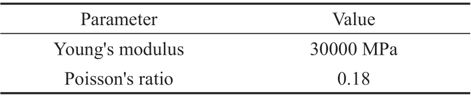
Table 1 Linear concrete model properties

Table 2 Nonlinear concrete model properties
2.2 Model verification and parameters calibration
Liet al. (2020) experimentally investigated the response of a normal strength concrete slab subjected to contact explosion of 1 kg of explosive charge, thetest specimen slab dimension was 200 cm long, 100 cm width, and 10 cm thickness as shown in Fig. 3. The slab had upper and lower reinforcement mesh using 12 mm bar diameter, where reinforcement spacing in the longitudinal direction was 100 mm and 200 mm iin the transversal direction. The compression strength of the slab concrete was 39.5 MPa and it was simply supported at its transversal edges. The real damage to the top and bottom face of the slab after explosion is shown in Fig. 4,where the dimension of spall damage of the top surface was 390 mm.
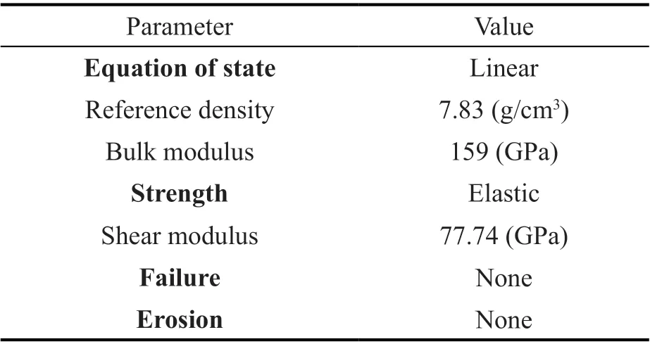
Table 3 Steel reinforcement properties

Table 4 Explosive material (TNT) properties

Table 5 Air properties
A numerical FE model is created using the technique and the parameters presented in Section 2.1. All material parameters have the same values presented except the concrete material strength, which is taken in this model as equal to 39.5 MPa instead of 35 MPa to simulate the strength of the concrete in the experiment. The slab is modeled by solid elements representing the concrete nonlinear material and the steel reinforcement is modeled by beam elements representing the steel material properties, and both of the concrete and reinforcement are fully contacted and are present the Lagrange part of the model as shown in Fig. 5. The air and the explosive charge (TNT) were modeled using Euler solid elements.The Euler part (air) extends around the Lagrange part(slab) from all sides. There is enough space to allow interaction between the Lagrange part and the Euler part.The Euler-Lagrange interaction is fully coupled.

Fig. 1 (a) Rectangle compartment geometry, (b) whole analytical model, concrete, steel reinforcement, air and TNT
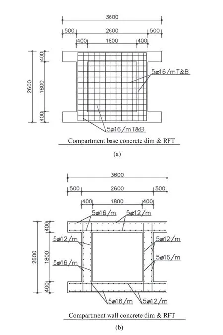
Fig. 2 Reinforcement detailing (a) in the compartment′s base and (b) in the wall of the compartment

Fig. 3 (a) Slab subjected of contact explosion and (b) slab dimensions and reinforcement (Li et al., 2020)
The analysis is carried out using Autodyn (Ansys,2020) software to verify the damage pattern and the deformation of the slab. The numerical simulation shows that the detonation of the explosive charge generates a spall of concrete of about 370 mm as shown in Fig. 6.The damage pattern of the top and bottom face of the slab is shown in Fig. 7.
By comparing the results of the experiment and results of the FE model simulation, it is clear that there is very good agreement between them, especially in the dimension of the concrete spall and the damage pattern.Therefore, the presented analytical technique and parameter values can be used with an accepted degree of confidence to investigate the response of such structures subjected to this type of blast loading.
3 Material linearity and nonlinearity
The analysis is carried out for two models. The first is a basic model which has 40 cm thickness and the other is similar to the basic model with 30 cm thickness. Each structure is subjected to three different explosive charge quantities, 1.63, 13, and 16 kg of TNT. The explosive charge is located at the center of the compartment and 1.5 m above the top of the base. All models are analyzed twice, the first using a linear material model and the second using a nonlinear material model. In the nonlinear material modeling, both models of 30 and 40 cm thickness subjected to 16 kg of TNT explosive charge failed due to the excessive stresses at the support joints and have been eroded, so the output for these cases have not been introduced. The output for some selected results is summarized in the following figures.
Figure 8 illustrates the maximum blast wave pressure in air in front of the wall of the compartment for every charge, and for every model using linear and nonlinear material.
It is clear that the pressure is proportional with the explosive charge quantity is not significantly affected by the material behavior (material nonlinearity), and increases in proportion to the thickness of the wall. This can be explained as follows: by increasing the thickness of the wall, the increase in its rigidity results in reflecting higher pressure waves, which leads to excessive wave pressure. This is clearly seen as the explosive charge quantity increases.
Figures 9 and 10 present the maximum normal stresses in the longitudinal wall, and at a node located at the center of the wall. The stresses are in the direction of the global coordinate system in theXandZdirections,respectively, which correspond to the normal stress in the plane of the wall in both directions. By examining the results presented in both figures, the following conclusions can be drawn:

Fig. 4 (a) Top and (b) bottom face of slab after explosion (Li et al., 2020)
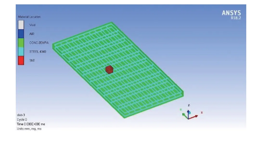
Fig. 5 Numerical model of tested slab
Fig. 6 Concrete spall of top face after explosion

Fig. 7 (a) Top and (b) bottom damage face of numerical model of slab after explosion
• The linear material model always gives results higher than the nonlinear material model, and this variation increases as the explosive charge increases.It can be seen that the difference is about 5% in the small amount of explosive charge, and increases as the explosive charge increases to reach about twice the value in the medium explosive charge quantity. The difference in the stresses between both material models decreases as the wall thickness increases.

Fig. 8 Maximum pressure
• In the nonlinear material model, the variation in the stress is small with regard to the model′s thickness,and this is valid for every explosive charge quantity.
• In the nonlinear material model, the stress in theXdirection (short direction of the wall) is greater than the stress in theZdirection (longitudinal direction of the wall) and reaches to nearly 15 %.
The maximum normal stresses in the transverse(short) wall are presented in Figs. 11 and 12 as stated above. The stresses are in the direction of the global coordinate system in theYandZdirections, respectively,which correspond to the normal stress in the plane of the wall in both directions. By examining the results presented in both figures, the first bullet item above is still valid, as well as the following observations:
• Generally, the stresses in the short wall are lower than the stresses in the long wall, which can be explained as follows: since the short wall is set at a longer distance from the explosive charge, the pressure wave decreases as much as it travels, and consequently, the generated blast wave pressure acting on the short wall is lower.
• In the nonlinear material model, the variation in the stress starts to be noticeable with regard to the model′s thickness, and is normally lower in larger wall′s thickness.
• In the nonlinear material model, the stresses in both theYandZdirections are considerably different,which extends to 30 %. This is because the short wall acts like one way slab, which leads to higher stresses in the short direction (theYdirection).
Fig. 9 Maximum stress in center of the longitudinal wall in the X direction
Fig. 10 Maximum stress in center of the longitudinal wall in the Z direction
• It can be conceived from the previous remarks that the transverse direction suffers from higher stresses than the longitudinal direction in the side wall, and therefore special attention must be given to transverse reinforcement in the side walls.
• Blast has a local effect and is almost equal especially in the long wall and far away from its sides,which causes nearly equal bending normal stresses in both directions.
The maximum normal stresses in the base is illustrated in Figs. 13 and 14. The results are presented for a node located at the center of the base, and the stresses are in the direction of the global coordinate system in theXandYdirections, respectively, which correspond to the normal stresses in the plane of the base in both directions. By investigating the results presented in both figures, in addition to the first bullet item in the results for the longitudinal wall, the following observations are presented:
• In the nonlinear material model, the variation in the stress is about 15% with regard to the model′s thickness. The thickness in the larger wall results in lower stresses.
• In the nonlinear material model, the stresses in both theXandYdirections are close to each other in both wall′s thickness with a difference of not more than 8%. This can be conceived as the local effect of the blast load rather than the normal load distribution of the load on the slab.

Fig. 11 Maximum stress in center of the transversal wall in the Y direction
Fig. 12 Maximum stress in center of the transversal wall in the Z direction
The maximum displacement at the center of the short wall, long wall and the base are presented in Figs. 15, 16,and 17, respectively. From these figures, the following conclusions can be drawn:
• With regard to the horizontal displacement in theXandYdirections, which correspond to the displacement in the short and long wall respectively,and in the low explosive charge, the displacement in the short wall is less than the displacement in the long wall by about 50% in both the linear and nonlinear material models with thickness 30 cm, and is lower by about 40% in both linear and nonlinear material models with thickness of 40 cm.
• With regard to the horizontal displacement in theXandYdirections, which correspond to the displacement in the short and long wall, respectively,and in the medium explosive charge, the displacement in the short wall is less than the displacement in the long wall by about 37% in the linear model and by about 70%in the nonlinear material model with thickness 30 cm, and is lower by about 46% in the linear model and by about 66% in the nonlinear material model with a thickness 40 cm.
• Generally, the linear material model gives lower displacements than the nonlinear material model.The difference increases as the blast charge increases and may reach more than twice the nonlinear model′s value as in the long wall. The difference decreases as the thickness increases, and the difference in the long wall is higher than that in the short one.

Fig. 13 Maximum stress in center of the base in the X direction

Fig. 14 Maximum stress in center of the base in the Y direction
• In the base, both models give close results.
4 Reinforcement ratio
The strategy adopted for the reinforcement ratio considered in the numerical models is based on increasing the reinforcement ratio by a considerably large value and examining if this large increase in the reinforcement ratio has a significant effect on the response. The type of response (damage, displacement and stress) is significantly affected by this change due to different explosive charge quantities and different thickness of the models.
Fig. 15 Maximum displacement in the X direction

Fig. 16 Maximum displacement in the Y direction
Fig. 17 Maximum displacement in the Z direction
The aim of this section is to explore the degree that the reinforcement ratio is important and the type of response.
The study is carried out by using the same models presented in Section 3 (hereafter called the model with RFT 1). By increasing the reinforcement ratio in the models by 300% and 200% for the vertical and horizontal reinforcement, respectively (hereafter called model with RFT 2), keeping all other conditions as previously introduced, the nonlinear material model was used in the analysis. The analysis is carried out for models with 30 and 40 cm thickness. The output of the selected results is introduced in the following figures.
The maximum damage index in the studied models is presented in Fig. 18. The observations include the following:
• In the small explosive charge quantity, the damage index is about 1% in all models, and the reinforcement ratio has no effect on the damage index.
• In the medium explosive charge quantity, the damage index in both models of thickness 30 cm reaches about 100% without no effect on the reinforcement ratio.
• The damage index in the 40 cm thickness models with RFT 1 and RFT 2 reaches about 80%and 72%, respectively, which means that increasing the reinforcement ratio improved the damage index by about 10%.
• It can be concluded that the damage index is not significantly influenced by changing the reinforcement ratio in these structures.
The maximum normal stresses in the longitudinal,transverse wall and the base at a node located at the center of each one are presented in Figs. 19, 20 and 21,respectively, showing the stresses in the direction of the global coordinate system inX,Y, andZ, respectively.By examining the results, the following conclusions are drawn:
• In the models of thickness 30 cm subjected to a small explosive charge quantity, the stresses in the three figures are not significantly affected by changing the reinforcement ratio, and are generally low.
• In the models of thickness 30 cm subjected to a medium explosive charge quantity, the stresses have been reduced by about 7%, 12%, and 30% in the longitudinal, transverse wall and the base, respectively,due to the increase of the reinforcement ratio.
• In the models of thickness 40 cm subjected to a small explosive charge quantity, the stresses have been reduced by about 35%, 30%, and 42% in the longitudinal, transverse wall and the base, respectively,due to the increase of the reinforcement ratio, and are generally low.
• In the models of thickness 40 cm subjected to a medium explosive charge quantity, the stresses have been reduced by about 9%, 24%, and 28% in the longitudinal, transverse wall and the base, respectively,due to the increase of the reinforcement ratio.
The maximum displacement at the center of the short wall, long wall, and the base perpendicular to their planes are presented in Figs. 22, 23 and 24 respectively.By investigating these figures, the following conclusions are drawn:

Fig. 18 Damage index
Fig. 19 Stress in the X direction at the longitudinal wall
Fig. 20 Stress in the Y direction at the transverse wall

Fig. 21 Stress in the X direction at the base
• In all models with thickness 30 and 40 cm subjected to a small explosive charge quantity, the effect of increasing the reinforcement ratio on the displacement is almost insignificant.
• For the models with thickness 30 cm subjected to a medium explosive charge quantity, there is a significant effect of increasing the reinforcement ratio on decreasing the displacement. The reduction in displacement is about 37%, 39%, and 14% for the short wall, long wall, and the base, respectively.
• For the models with thickness 40 cm subjected to a medium explosive charge quantity, have a significant effect of increasing the reinforcement ratio on decreasing the displacement, but with lower reduction ratios. The reduction in displacement is about 17%, 15%, and 23%for the short wall, long wall, and the base, respectively.
• As a general conclusion from the previous notes, in structures with various thicknesses subjected to a small blast load, the reinforcement ratio has almost no significant effect on the displacement. When these structures are subjected to a medium blast load, the influence of the reinforcement ratio appears, and this influence decreases as the thickness increases and vice versa.
5 Effect of structural geometry
In this section, the effect of structural geometry is investigated. This is achieved by changing the base dimensions of the compartment (width and tall) and keeping the net floor area constant to obtain models with various rectangularity ratios for the base, and no change in the height value (6 m). The study is based on the same model geometry and dimensions presented in Section 3 with thickness 40 cm, which has a rectangularity ratio equal to 1.45, then changing its width and height values,keeping the net floor area constant to obtain various models with different rectangularity ratio, while keeping the explosive charge location as previously introduced.The nonlinear material model is used in the analysis.The output of the selected results is introduced in the following figures.
Another model is created with a circular cross section with the same net floor area as the rectangular one. The model is shown in Fig. 25. The output results of this model are presented in the following figure with rectangularity ratio = 0.
Figure 26 illustrates the maximum blast wave pressure in the air in front of the compartment′s wall,for every charge, for every model using the nonlinear material. By examining this figure, the following conclusions are presented:
• It is clear that the pressure is proportional to the explosive charge quantity.
• In the presence of small explosive charges, the pressure ranges from 0.33 MPa atr=1 to 0.67 MPa atr=1.75, the range is about two times the value in the case ofr=1 which has the lowest value. The pressure in the circular section is 0.63 MPa, which is near to the upper part of the previous range.
• In the case of medium explosive charges, the pressure varies in the range from 1.38 MPa atr=1 to 3 MPa atr=2. The lowest value is atr=1. The pressure in the circular section is 4.18 MPa, which is much higher than the upper limit of the previous range.
Fig. 22 Displacement in the X direction

Fig. 23 Displacement in the Y direction
Fig. 24 Displacement in the Z direction

Fig. 25 Circular compartment dimensions
• This wide range of pressure scattering can be perceived as a result of blast wave amplification due to the reflection of the wave and the air structure interaction.
The maximum normal stresses in the longitudinal wall and the base at a node located at the center of each one are presented in Figs. 27, 28, 29 and 30 respectively,showing the stresses in the direction of the global coordinate system in theXandZdirections for the longitudinal wall, and in theXandYdirections for the base. By examining the presented results, the following conclusions are drawn:
• For the longitudinal wall, and for a small explosive charge quantity, the stress increases as the rectangularity ratio increases.
• For the base, and for a small explosive charge quantity, the stresses in both directions are inversely proportional to the rectangularity ratio, and this relationship is the inverse of the relationship in the wall.
• For the longitudinal wall and the base, and for a medium explosive charge quantity, there is no clear pattern for the relationship. The stress goes up and down with no obvious pattern, and can be perceived again as a result of blast wave amplification due to the reflection of the wave and the air structure interaction. Note that the stress in both directions in the wall is close in many of the rectangularity ratios, and also in the base. This can be perceived as the local effect of the blast load on the wall or the base instead of the usual load distribution over the slab.
• For the circular model, and for a small explosive charge quantity, the stresses in the wall and the base in both directions are very close. The value of the stress in the wall in the circular model is lower than the lowest stress in the wall in the rectangular model. The value of the stress in the base in the circular model is close to the stress in the base in the rectangular model with rectangularity ratio = 1.25.
Fig. 26 Comparison of pressure for compartments of various rectangularity ratios
Fig. 27 Comparison of stress at center of the wall in the X direction for compartments of various rectangularity ratios
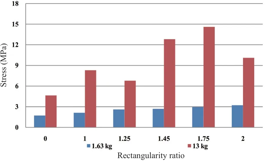
Fig. 28 Comparison of stress at center of the wall in the Z direction for compartments of various rectangularity ratios
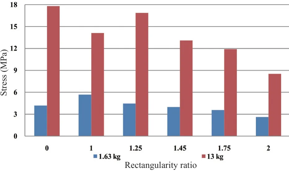
Fig. 29 Comparison of stress at center of the base in the X direction for compartments of various rectangularity ratios
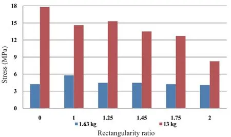
Fig. 30 Comparison of stress at center of the base in the Y direction for compartments of various rectangularity ratios
• For the circular model, and for a medium explosive charge quantity, the stresses in the wall are different in each direction; it is higher in the tangential direction. The stress in the base is equal for both directions. The stresses in the wall for both directions are lower than the stresses in the wall in the rectangular model of any rectangularity ratio. The stress in the base is higher than the stresses in the base in the rectangular model of any rectangularity ratio, and is slightly higher than the stresses in the model withr=1.25.
The maximum displacement at the center of the short wall, long wall and the base are presented in Figs.31, 32 and 33 respectively. By examining these figures,the following conclusions are drawn:
• The displacement in the short wall, long wall,and the base, and for a small explosive charge quantity,has small values, and shows no large differences for various rectangularity ratios.
• The displacement in the short wall, and for a medium explosive charge quantity, tends to decrease as the rectangularity ratio increases. In the long wall and the base, there is no obvious relationship between the displacement and the rectangularity ratio.
• For small and medium explosive charge quantities, the circular model exhibits displacement values that are much lower than the rectangular models.
6 Conclusions
This study presents the response of compartment structures when subjected to blast loads from the following aspects: linear and nonlinear material model,reinforcement ratio, structural geometry, and the use of RC-sand sandwich walls instead of solid ones.Comprehensive results are obtained and analyzed for each aspect, and remarkable effects of the aforementioned factors on the dynamic response are observed.
The stresses caused by blast loads in the linear model exceed their corresponding values in the nonlinear model by 5% to 100%. This increase in stresses caused by assuming linear material increases as the explosive charge or the wall thickness increases. The local effect of the blast load on stresses is much larger than the effect of all other (traditional) loads.
The wall and slab reinforcement ratios have significant effects on the response of the compartments.Generally, increasing the reinforcement ratio enhances the behavior of the compartments by reducing the damage index and the stresses by about 7% to 42% in the studied cases. Nevertheless, the reinforcement ratio has almost no significant effect on the displacement when the compartment is subjected to small blast loads. When the compartments are subjected to medium blast loads,the influence of reinforcement ratio becomes noticeable;this influence decreases as the element thickness increases and vice versa.
It is suggested, for future research, to investigate the effect of using FRP, introducing a new form of the wall and base instead of the solid RC like RC-sand sandwich walls or the use of metamaterials with featured properties, to improve the response of compartment structures to blast loads.
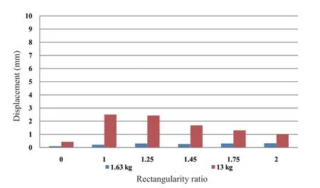
Fig. 31 Comparison of displacement in the X direction for compartments of various rectangularity ratios

Fig. 32 Comparison of displacement in the Y direction for compartments of various rectangularity ratios
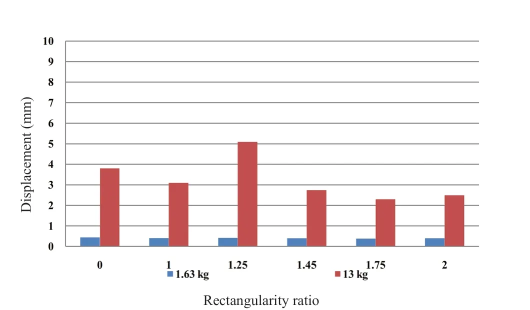
Fig. 33 Comparison of displacement in the Z direction at the center of the base for compartments of various rectangularity ratios
杂志排行

Earthquake Engineering and Engineering Vibration的其它文章
- A review of the research and application of deep learning-based computer vision in structural damage detection
- Experimental study of vertical and batter pile groups in saturated sand using a centrifuge shaking table
- Analytical evaluation and experimental validation on dynamic rocking behavior for shallow foundation considering structural response
- Effect of geofoam as cover material in cut and cover tunnels on the seismic response of ground surface
- Dynamic response of concrete face rockfill dam affected by polarity reversal of near-fault earthquake
- Analyzing uncertainties involved in estimating collapse risk with and without considering uncertainty probability distribution parameters