Applications of carbon nanomaterials in perovskite solar cells for solar energy conversion
2021-11-16KatherineMooreWeiWei
Katherine Moore,Wei Wei
Department of Mechanical Engineering,Wichita State University,1845Fairmount St,Wichita,KS,67260,USA
Keywords:Carbon nanomaterials Perovskite solar cells Solar energy
ABSTRACT
1.Introduction
The increasing demand of global energy and the concerns about the climate and environmental have stimulated the intensive exploration for renewable energies.Solar energy is unarguably the largest clean energy source.Furthermore,the conversion of solar light into electricity has been identified as the most promising routes to store and utilize solar energy,leading to the considerable development of solar cells[1].The current market of solar cells is dominated by crystalline silicon solar cells.However,they have a higher cost for electricity production than fossil-fuel-based electricity,which promoted great efforts to develop“Next-generation”solar cell technologies with low cost and simple fabrication.One of them is the recent developed solar cell based on hybrid organometallic halide perovskites,which attracted special attention because of the highly reported power conversion efficiency(PCE),easy fabrication,and low cost[2–7]..
Organic-inorganic hybrid perovskites exhibit unique structures and excellent optical and electrical properties[8,9].The most attractive one is a class of semiconductive organolead halide perovskites with an AMX3(X=Cl-,Br-,or I-)structure(Fig.1)[10].In this structure,M site is the lead cations;X sites are halide anions;and A site is organic component.The inorganic/organic hybrid metal halide perovskites show excellent properties for solar cells,such as suitable band structures,good ambipolar carrier transport,and long carrier lifetime[11–14].
Miyasaka et al.pioneered the application of the hybrid organolead halide perovskite compounds for DSSCs,in which CH3NH3PbBr3and CH3NH3PbI3perovskite compounds were exploited as sensitizers for mesoscopic TiO2films and the I3-/I-redox as a liquid electrolyte,achieving a PCE up to3.8%[15].Furthermore,Park et al.increased the PCE to6.54%by optimizing the concentration of CH3NH3PbI3perovskite sensitizer and post-annealing temperature[16].However,the performance of those solar cells decreased rapidly because the perovskite sensitizers dissolved in the liquid electrolyte.This issue was solved by Snaith and coworkers[17]and Park and coworkers[12].They replaced the liquid electrolyte by[2,2′,7,7′-tetrakis-(N,N-di-p-methoxyphenylamine)-9,9′-spiro-bifluorene](spiro-MeOTAD)for organolead halide perovskite-sensitized TiO2cells,leading to a PCE of9.7% for the CH3NH3PbI3/spiro-MeOTAD cell [12]and7.6% for the CH3NH3PbI2Cl/spiro-MeOTAD cell[17]with an excellent stability over 500h.Such a high PCE was achieved with a submicron thick TiO2film due to the large optical absorption cross section(absorption coefficient of 1.5*104cm-1at550nm)of the perovskite nanoparticles[12].The PCE was further increased up to12%with open circuit voltage(Voc)of0.997 V when spiro-MeOTAD was replaced by poly-triarylamine(PTAA)as a hole transportation material(HTM)[18].Since then,great efforts in the performance of perovskite solar cells(PSCs)has been reported,leading to impressive efficiencies over22.1%[19–22],which are even comparable with commercialized Si solar cells.Furthermore,the fabrication cost of Si solar cells are much higher than that of PSCs.
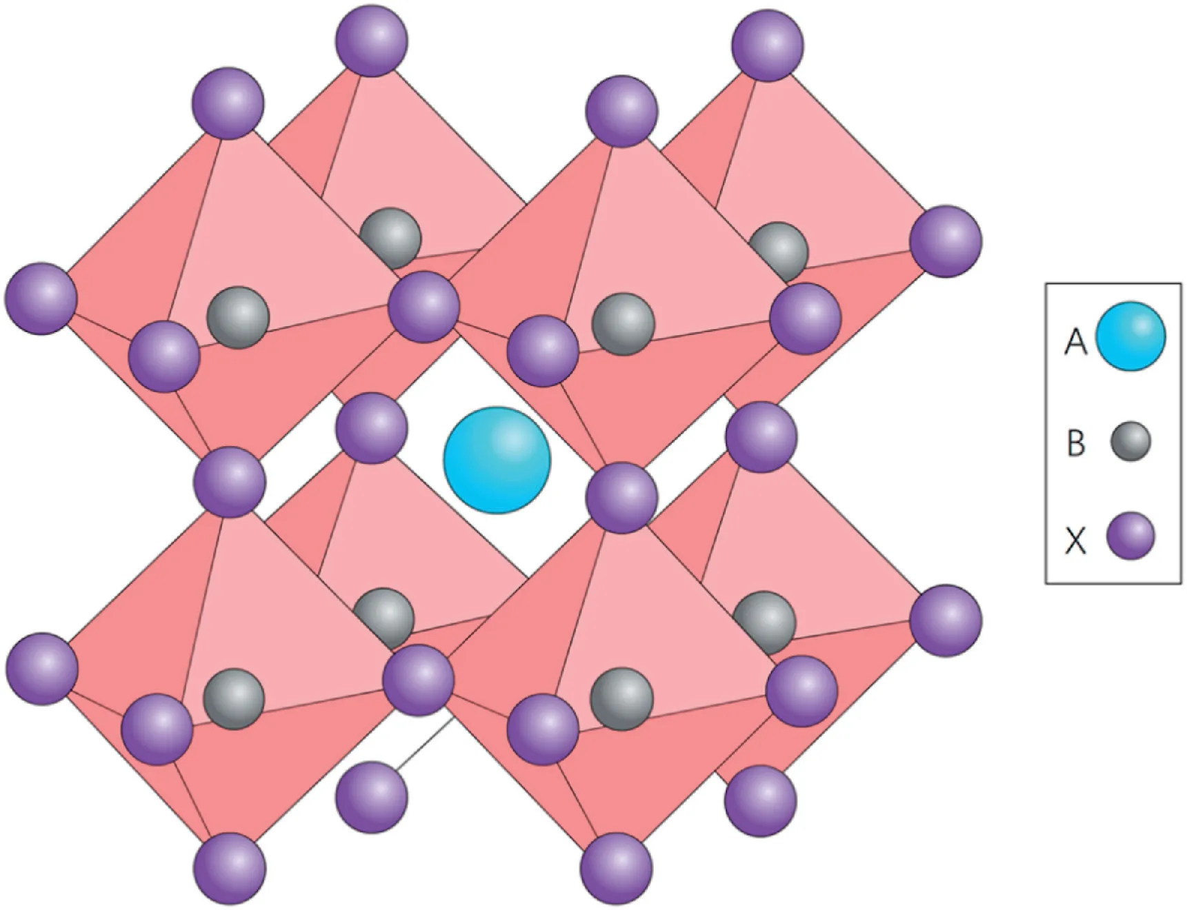
Fig.1.Cubic perovskite crystal structure.For photovoltaically interesting perovskites,the large cation A is usually the methylammonium ion(CH3NH3),the small cation B is Pb and the anion X is a halogen ion(usually I,but both Cl and Br are also of interest)[6].
Undoubtedly,organometal halide perovskite solar cell is an outstanding photovoltaic device.In this review,we will first provide a brief introduction of device structures and carbon materials.The importance and roles of carbon materials in PSCs will also be explained.Then,we will discuss the applications of various carbon materials in PSCs.Their potential in improving device performance will also be discussed.In the end,we will present a summary and perspective on the future research directions in carbon-based PSCs.
2.Evolution of device structures
The initial configuration of PSC named mesoscopic PSC(MPSC),which is similar to that of DSSCs with three parts:a methylammonium lead iodide perovskite deposited on a mesoporous metal oxide scaffold/dense TiO2layer coated on fluorine-doped tin oxide(FTO)glass as a photo-electrode,spiro-OMeTADas a hole-transporting layer(HTM),and silver(or gold)thin film as a counter electrode(Fig.2a).Soon,however,researchers revealed the possibility to replace mesoporous n-type TiO2with nanoparticle Al2O3film for the solar cell(Fig.2b)[17].Furthermore,the PCE of Al2O3-based solar cell was further improved to12.3%by optimizing Al2O3film prepared at low temperature of150°C[23].
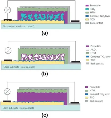
Fig.2.Evolution from a mesoscopic to a planar embodiment of the perovskite solar cell.(a)Nanocomposite embodiment of a PSC where the mesoscopic TiO2scaffold is infiltrated by the perovskite.(b)Meso-superstructured PSC employing a film of Al2O3nanocrystals covered with a conformal overlayer of CH3NH3PbI3perovskite.(c)Cross-section of a planar heterojunction solar cell lacking the TiO2mesoporous scaffold[129].
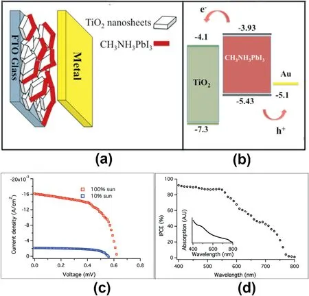
Fig.3.(a)Scheme of the device structure.(b)Energy level diagram of the CH3NH3PbI3/TiO2heterojunction solar cell.(c)J–V characteristic of the lead iodide perovskite/TiO2mesoscopic heterojunction solar cell.(d)IPCE spectrum of the device.Inset:absorption spectra of the perovskite layer on the TiO2[30].
For the above MPSCs,the device usually employed a configuration of n-i-p(TCO/n-contact/perovskite/p-contact/metal),which was evolved from DSSCs,specifically from n-type DSSCs.Evolved from the architecture of p-type DSSCs or organic solar cells,an inverted-type MPSC was developed with a configuration of p-i-n(TCO/p-contact/perovskite/ncontact/metal)[24].The first inverted-type MPSC was reported by T.F.Guo and co-worker in2014,using NiO inorganic metal oxide nanocrystalline as p-type electrode and[6,6]-phenyl C61-butyric acid methyl ester(PC61BM)as the n-type contact[25].A PCE of9.51%was achieved by such p-type perovskite-sensitized solar cells.Then,T.F.Guo and co-workers introduced the use of low-temperature sputtered NiOx thin film as an effective electron-blocking layer instead of solution-processed NiOx for mesoscopic NiO/MAPbI3MPSCs,improving the efficiency of inverted-type MPSCs to11.6%[26].
Guo et al.first successfully demonstrated the planar perovskite/fullerene structure,showing a4%efficiency[27].The poor inferior film quality and inadequate absorption of the perovskite film were the main reason for the low reported efficiency.A higher efficiency of15.4% for the planar perovskite structure was achieved by using a dual source vapor deposition,which provides dense and high quality perovskite films[20].Recently,the efficiency of19% was achieved for the planar structure through interface engineering[22].These results confirmed that the planar structure could achieve comparable device performance as the mesoporous structure.Similar to MPSCs,the planar structure can also be categorized into two different types based on which selective contact is used on the bottom,namely,regular(n-i-p)and inverted(p-i-n).The regular n-i-p structure has been developed based on the structures of dye-sensitized solar cells.The p-i-n structure is developed from the organic solar cells(Fig.2c).
The PSCs’s structures discussed before all employed HTM in the operation of PSCs.However,HTMs are very expensive,which increases the cost for PSCs.As a result,their approach to low-cost photovoltaic devices has been limited.It was found that hole-conductor free mesoscopic perovskite solar cells can also operate very well[28,29].L.Etgar et al.first reported the HTM-free perovskite solar cell back in2012.The PCE of5.5% was obtained[30].In the device,a perovskite/TiO2heterojunction was formed,in which the MAPbI3nanoparticles has two roles:light harvester and hole-conductor.This rendering superfluous the use of an additional HTM(Fig.3a and b),leading to a PCE of5.5%(Fig.3c and d).Then in2014,the group improved the efficiency to10.85%[31].It was revealed that the depletion layer width created at the TiO2/MAPbI3junction has huge impacts on the photovoltaic performance of theHTM-free perovskite solar cell.However,the back content in such devices was still noble metal of gold,which was expensive and required energy intensive fabrication process.These issues may slow the process of PSC commercialization.
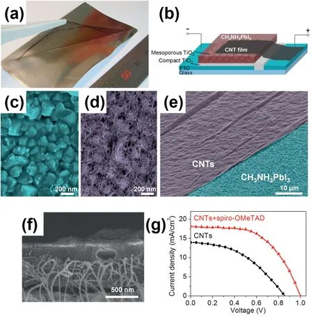
Fig.4.(a)Photo of freestanding CNT film lifting by tweezers to transfer onto other substrates.(b)Schematic of CH3NH3PbI3perovskite solar cell with CNT film electrode.(c)Top view SEM images of CH3NH3PbI3perovskite substrate before and(d)after CNT transfer.(e)Tilted SEM image of CH3NH3PbI3perovskite substrate(blu6e)partly covered by CNT film(purple).(f)Cross section SEM image of CNT film after spiro-OMeTAD infiltration.(g)J-V curves of a solar cell with and without spiro-OMeTAD at1sun[45].
Carbon nanomaterials,such as nanotubes(CNTs)and graphene,possess excellent stability,low cost and facile processability[32].They have been reported as alternative HTM and counter electrode(CE)materials for different kinds of solar cells.In the following section,the applications of carbon materials in PSCs will be discussed.
3.Applications of carbon materials
3.1.As hole transport material
Hole transport materials(HTMs),which are the layer next to perovskite layer,has two functions,namely,hole collection and transportation.The requirement for a good hole transporting layer is its HOMO energy level should be compatible with the perovskite valence band.Besides,other properties are also required,such as excellent thermal,photochemical stability,and hole mobility,and minimal absorption of the solar spectrum including visible and near-IR region[33].
3.1.1.Carbon nanotubes(CNTs)
Very recently,carbon nanotubes(CNTs)which is one-dimensional carbon materials have attracted great attention because of their excellent electrical,optical,chemical and mechanical properties[34,35].Furthermore,CNTs also possess other excellent properties,including excellent durability and flexibility,low reflectance,and ease of preparation[36,37].
SWCNTs have been regarded promising for their mechanical flexibility,earth-abundant carbon composition,easy synthesis,and direct roll-to-roll processability[38].Regarding the structure of SWCNTs,they can be considered as the simplest class of carbon nanotubes.Its architecture can also be described as a single-layer graphene rolled in a cylindrical shape,which has the diameters of0.4–3.0nm[39].Iijima first discovered the SWCNT in early1990s.After that,the research of its synthesis and properties increased tremendously[40].Single-walled carbon nanotubes are of great interest for use in organic and hybrid photovoltaic solar cells due to their combination of attractive properties such as high charge carrier mobilities[41,42],long-lived charge transport characteristics[43],large aspect ratios,and high tensile strength[44].
There are a few studies have been published for the applications of carbon nanotubes in PSCs(Table1).Li et al.reported a carbon nanotube film which is transparent and highly resistive to be used as the sole HTMCE layer in a PSC.A PCE of7%was obtained[45].Fig.4a shows a photo of the obtained CNT film which was mechanically strong and freestanding.Fig.4b presents the cell structure which is consisted of layers of fluorine-doped tin oxide(FTO)/TiO2compact layer/mesoporous TiO2/CH3NH3PbI3/CNT film.A dense layer of CH3NH3PbI3perovskite nanocrystals was formed on top of the mesoporous TiO2,as shown in Fig.4c.As shown in Fig.4d,the flexible CNT network could coat the rough surface of perovskite after transfer.As a result,an increased interface area between perovskite and CNT were obtained and an improved electrical contact were achieved.Fig.4e shows the SEM image of the perovskite substrate(which was false-colored in blue)partly coated with a CNT film(which was false-colored in purple).Moreover,the conventional hole-transporting material(spiro-OMeTAD)was incorporated into CH3NH3PbI3/CNT perovskite solar cell,as shown in Fig.4f.From the SEM image of the corporation,one can see that the HTM not only covered the CNT network but also wrapped around the CNT bundles.As a result,the photovoltaic performance improves significantly(Fig.4g).In another report published by Li et al.,free standing carbon nanotubes films was employed as a hole conductor in PSCs.The perovskite material used was MAPbBr3and the efficiencies up to5.82% was achieved.The fabricated solar cells exhibit higher Voc than solar cells with spiro-OMeTAD as HTM.The highest value of1.45V was reported.In addition,the concept of all-perovskite tandem solar cells was demonstrated by testing the transparent MAPbBr3/CNT solar cells with double side illumination and assembled with a MAPbI3solar cell[46].Besides,carbon nanotube-HTM composites with an additional thermally evaporated silver CE were also reported[47,48].Boschloo et al.reported a highly efficient,single-walled carbon nanotube based hybrid drop-cast Spiro-MeOTAD-counter electrode for PSCs with industrially viable processing[48].It was also revealed by Geng et al.that addition of SWCNTs can improve the P3HT crystallinity.This is because the crystallization of the polymer is benefited by the nanotube-induced π-π stacking interaction,which results in local molecular orientation of P3HT in a nanoscale dimension along the wall of carbon nanotubes[49].In addition to improving the carrier mobility,the interaction between the polymer and CNT may also change the P3HT’s optical band gap[50].Furthermore,the kinetics of carrier diffusion,charge transfer at interface,and recombination can also be tracked by using the combination of CNT and HTL[51].
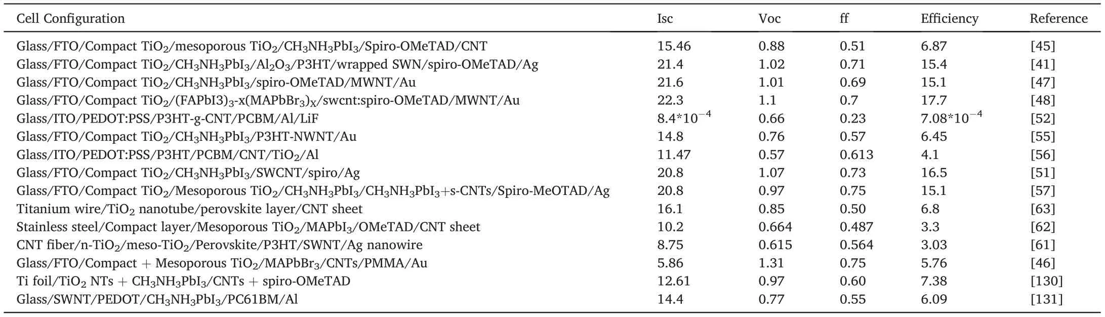
Table1 Summary of photovoltaic performance parameters of carbon nanotube-based perovskite solar cells.
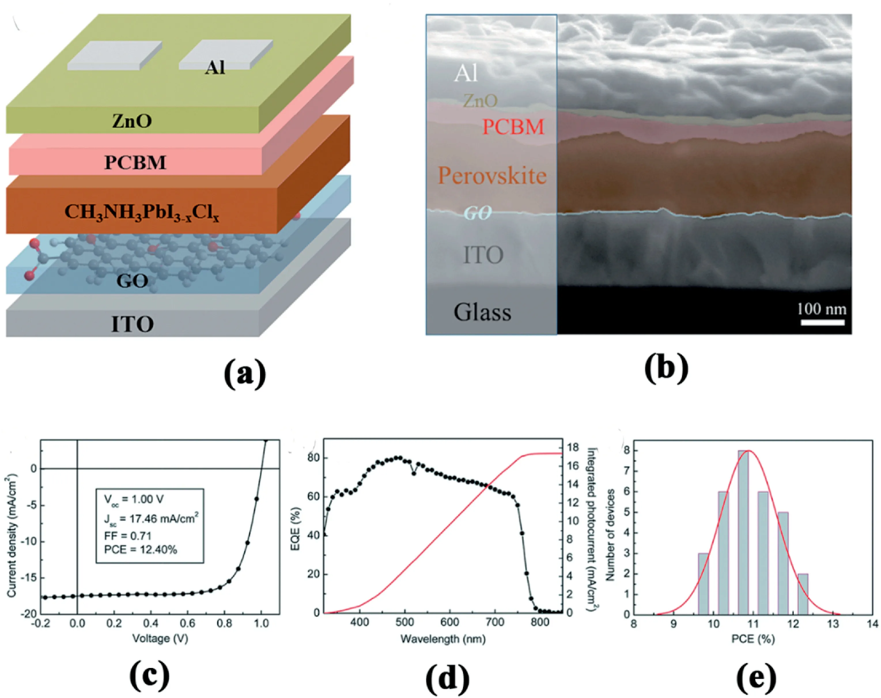
Fig.6.(a)Schematic of the inverted photovoltaic device configuration consisting of a structure of ITO/GO/CH3NH3PbI3-xClx/PCBM/ZnO/Al.(b)Cross-sectional SEM image of the optimized inverted device configuration.(c)J–V curve and(d)EQE spectrum of champion device employing2nm GO as hole conductor.(e)Histogram of PCEs measured from30devices[64].
P3HT with multiwall carbon nanotubes(MWNTs)has also been reported to have a similar band gap[52].Additionally,it has been confirmed by the theoretical study that P3HT could self-assemble around CNTs through its main chain.As a result,the interfaces between P3HT and MWNTs and the conjugation in the blend would be enhanced[53].Similarly,in Wang’s report,the electron recombination at the interface of MAPbI3/HTM can be reduced by a composite of P3HT and bamboo-structured carbon nanotubes(BCNs).Furthermore,the superior morphological structure with reduced grain boundaries for hole transport in the HTM layer was also observed[54].A perovskite solar cell using P3HT incorporating MWNTs as HTM showed an improved PCE,from4.12% to6.45%,due to an enhanced fill factor[55].P3HT with chemically-doped MWNTs could also increase the PCE of organic photovoltaic cells from3% to4.1%,due to enhanced carrier mobility[56].The properties of CNTs could be modified by functionalization,thus enhancing the PCE of PSCs.Zhang demonstrated an approach in which the sulfonate carbon nanotubes(s-CNTs)was incorporated,resulting in the grain size enhancement and the grain boundary reduction of the perovskite films.A high PCE of15.1%was achieved[57].
Due to the unique advantages of being lightweight and wearable,PVs in wire format with flexible structure have attracted increasing attentions in recent years[58–61].Peng developed a perovskite solar cell with a coaxial fiber-shape,in which the steel wire was used as anode and carbon nanotube film was used as cathode.A PCE of3.3%was achieved(Fig.5)[62].Furthermore,they investigated the effect of the thickness of compact TiO2layers as well as annealing temperature.As a result,the solar cell with50nm thick of TiO2and annealed at400°C showed the highest PCE(Fig.5e and f).In Peng’s another research,a cathodic deposition solution process has been developed to prepare perovskite layers with high coverage and uniformity on curve surfaces such as titanium(Ti)wires.When the modified Ti wire and transparent aligned carbon nanotube(CNT)sheet are used as two electrodes to produce a coaxial perovskite solar cell fiber(PSCF),a high PCE of7.1%also with a high open-circuit voltage of0.85V has been generated[63].
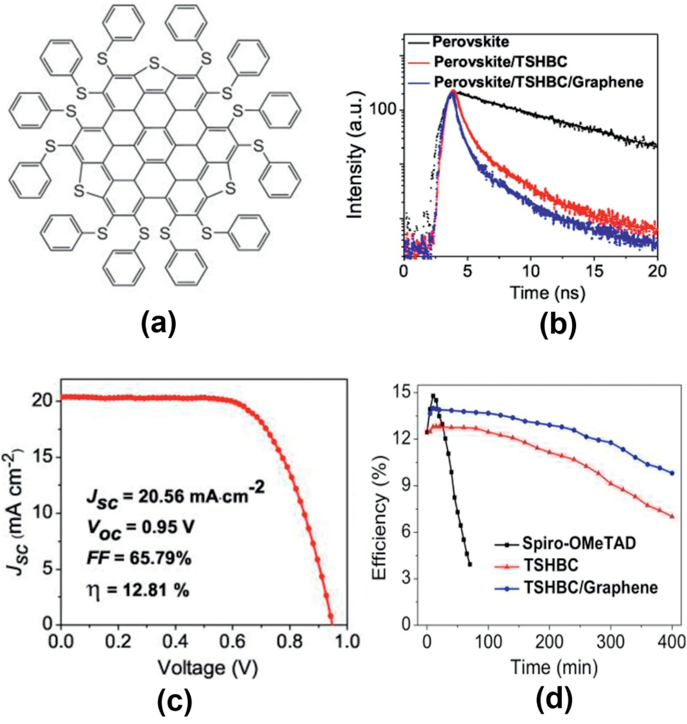
Fig.7.(a)Structures of TSHBC.(b)Transient PL spectra of films based on20nm HTM layers.(c)(c)Best I–V characteristics.(d)Efficiency variation of the devices stored under illumination at AM1.5G with the humidity of45%[68].
3.1.2.Graphene and its derivatives
Graphene and graphene derivatives have also been applied for different types of perovskite solar cells,including as hole transport materials because they possess excellent transport properties.Among them,graphene oxide(GO)was the first to be used as HTM in an inverted iodide/chloride mixed halide perovskite based planar-structured PSCs[64].Fig.6a shows the device structure,which is consisted of ITO/-GO/perovskite/PCBM/ZnO/Al layers.The main function of GO in this structure is to provide an efficient charge transfer from the perovskite layer.Fig.6b illustrates the cross-section SEM image of the device,in which the distinguishable planar layer-by-layer structure can be observed.The champion device with2nm GO as a hole conductor exhibits a PCE of12.4%(Fig.6c)with an average of11.1%(Fig.6e).Furthermore,the Jsccalculated by integrating the external quantum efficiency(EQE)curve is consistent with the corresponding Jscobtained from the J-V curves(Fig.6d).In next year,a similar inverted device architecture was employed,in which GO doped with both PEDOT:PSS and AgOTf were explored as HTM.Moreover,ZnO interlayer was eliminated in this case and gold was employed for electron collection instead of Aluminum[65].By introducing ammonia into GO,the resulting GO/NH3HTL improved the PCE of PSCs to16.11%.This can be explained by three reasons:(1)the crystallization of the perovskite structure have been improved;(2)the morphology has been modified to nearly complete coverage;and(3)the energy level alignment at the perovskite interface has been improved[66].Furthermore,GO has a high degree of oxygen contents,which results in high working function.However,such high oxygen contents lead to low conductivity.To enhance the performance of GO-based PSCs,various reduction approaches were adopted to decrease the oxygen contents.Nearly at the same time,reduced graphene oxide(rGO)which was prepared by solution processes was also explored as hole transport interlayer in both direct and inverted perovskite solar cells.Yeo et al.was the first to report the possibility to obtain the highly efficient inverted devices with the structure of ITO/rGO/-MAPbI3/PCBM/BCP/Ag using reduced GO[67].The inverted solar cells with single layered rGO(~3nm)show a20% improvement of performance compared with the PEDOT:PSS based solar cells.The larger and more oriented perovskite grains on rGO than on PEDOE:PSS is the main contributor to this improvement.
Using thiolated nanographene as HTM,associated to the MAPbI3perovskite further confirmed the potential of graphene-based HTM for efficient and stable mesoscopic perovskite solar cells[68].As shown in Fig. 7a, the chemical structure of the thiolate dnano-graphene(perthiolatedtrisulfur-annulated hexa-peri-hexabenzo coronene,TSHBC)allow the Pb–S bonds to be formed at the interface with the perovskite absorber,which leads to an intimate electronic contact between both components.As shown in Fig.7b,the transient photoluminescence provides the evidence of highly efficient charge transfer at the perovskite/HTM interface,which leads to a high PCE of 12.8%(Fig.7c).The incorporation of graphene sheets with high conductivity in the TSHBC layer to compensate for its intrinsic low charge mobility further improves the device performance.A record efficiency of 14% was observed when weight ratio of TSHBC:graphene is5:1.These improvements can be explained by the better hole transport ability and improved interface charge transportation.Furthermore,as shown in Fig.7d,under illumination at AM1.5G,the performance of PSCs with spiro-OMeTAD was degraded to25% within1h.In the mean time,TSHBE and TSHBC/graphene retained over60% and70% of its initial efficiency for400min,respectively.In the report of Zhu and co-workers,an ultrathin graphene quantum dots(GQD)layer was inserted between TiO2layer and perovskite layer in a mesoporous-structured PSCs.The efficiencies of PSCs improved from8.81%to10.15%as the results[69].The addition of GQDs accelerated the electron extraction rate which further improved the performance of the device.The transient absorption measurement provided the evidence.This finding highlighted the important role of GQDs,namely,facilitating the electron transfer from the perovskite layer to the electron collector.
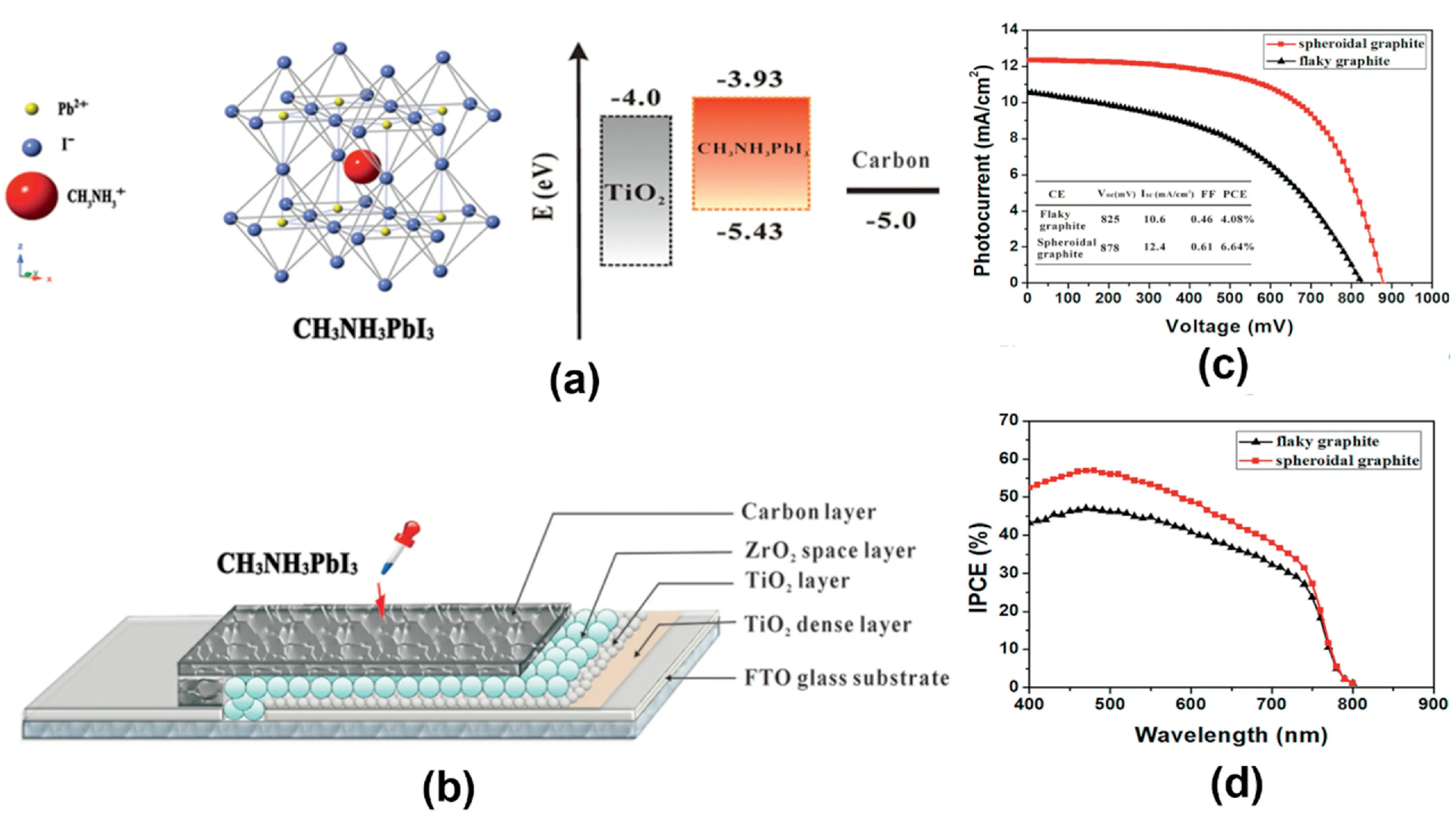
Fig.8.(a)The crystal structure of CH3NH3PbI3perovskite and the corresponding energy levels of TiO2,CH3NH3PbI3,and Carbon.(b)A schematic structure of a carbon based monolithic device.(c)Photovoltaic characteristics of CH3NH3PbI3perovskite/TiO2heterojunction solar cell based different carbon CEs.(d)IPCE as function of incident wavelength[94].
3.2.As electrode materials
Hole collecting electrode or counter electrode(CE)is an essential component in PSCs.Au is the most popular candidate as CE material in organo-metal PSCs which have been reported nowadays.However,Au is expensive which increases the materials cost further increases the manufacturing cost of the PSCs.Inexpensive metals,such as Ag,have been demonstrated as CE materials to be used with HTM layer.But the stability is the main issue since they cannot stay stable in HTM-free perovskite cells[70].To make PSCs competitive with commercial products under the fierce competition of the global photovoltaic market,low cost CEs with reasonable performance are in urgent need[71].
Low-cost carbon materials as highly available industrial materials have been applied in dye-sensitized solar cells which exhibit excellent performance[72–78].Furthermore,carbon are great candidates as CE materials for PSCs as well,which has been approved by the recently reported results[79,80].
In addition to the low-cost,the elimination of HTM and noble metal which can simplify the device fabrication are the other advantages that carbon materials can offer.Furthermore,as mentioned earlier,the sensitivity to moisture is the bottleneck of halide PSCs to be commercialized.The carbon-based PSCs have the potential to overcome this drawback since the carbon materials possess hydrophobic properties and good stability[81–89].Nevertheless,there are several problems which need to be solved before the carbon materials can replace the HTM and metal electrode in PSCs.First,the carbon materials have slow hole extraction rate because of which the charge recombination is increased.As a result,the carbon-based PSCs usually exhibit low open-circuit voltage(Voc)[90].Second,the carbon materials cannot provide the light back-scattering which the metal electrodes can offer.So,in the long wavelength range from500to800nm,the carbon-based PSCs exhibit low light harvesting efficiency and low IPCE.Third,the charge separation is insufficient at low photon energies[91–93].
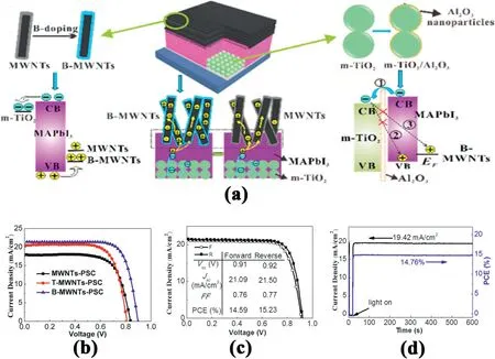
Fig.9.(a)Schematic illustration of cell configuration,B doping of MWNTs,charge behavior in C–PSCs and conformably coated thin Al2O3layer on preformed m-TiO2 film.(b)Photocurrent density–voltage curves.(c)J–V curves measured at forward and reverse scanning directions(100mV s-1).(d)Measured photocurrent output at the maximum power point(0.76V)and calculated PCE vs time[104].
To our best knowledge,the implementation of carbon materials in the counter electrode of CH3NH3PbI3based PSCs was first reported by Han’s group[94].In their report,a carbon black/graphite composite was deposited via screen printing technique on the PSC photoelectrode.The photoelectrode consists of FTO glass as the substrate,on top of which is the TiO2compact layer,followed by the mesoporous TiO2layer and ZrO2spacer layer.Finally,the CH3NH3PbI3perovskite sensitizer was drop-coated onto the mesoscopic carbon layer to complete the PSC’s manufacturing process,shown in Fig.8a and b.Under AM1.5solar light of100mW cm-2,the monolithic device based on the carbon black/flaky graphite exhibited a PCE of4.08%.Spheroidal graphite with better conductivity was also employed to further improve the device performance(Fig.8c).Furthermore,heterojunction devices exhibited an excellent photocurrent response from400to800nm(Fig.8d).Moreover,the device based on the spheroidal graphite showed a higher IPCE value than the device based on flaky graphite in the full-scale visible region of the electromagnetic spectrum.This is also consistent with the results from J-V measurements.Ignited by Han’s group success,various carbon materials have been applied as CE materials for PSCs aims to improve efficiency[95–97].By using TiO2nanosheet on the photoelectrode,the previous efficiency of6.64% was first improved to10.6%[98]and further to~11.6%[99]by optimizing the thickness of the carbon counter electrodes,reported by the same group.Lately,the relation between the thickness of carbon black/graphite film(3–15μm)and the PSCs performance was investigated by the same group.They found that,by employing a carbon black/graphite counter electrode with an optimized thickness of9μm,the best efficiency of the PSCs was achieved.Furthermore,Han’s group also collaborated with Gr¨atzel’s group on the fabrication of hole-conductor-free and fully printable perovskite solar cells[90].
Yang et al.explored various carbon materials,including commercial carbon paste[100],candle soot[101],single-layered or multilayered graphene[102],carbon nanotubes[103,104]as hole extractors for PSCs.An excellent contact between perovskite layer and carbon materials has been built because of their efforts.In another word,the recombination at interface is greatly suppressed and the charge collection enhanced.In his recent research,the boron(B)was dopped on multiwalled carbon nanotubes(B-MWNTs)to increase the work function,carrier concentration,and conductivity of MWNTs,which enhanced hole extraction and transport[104].Fig.9a shows the uniform MWNTs CE-based PSCs architecture.To efficiently improve the hole extraction and transport in the PSCs,the atomic B was employed as doping atom on the MWNTs.Indeed,the photovoltaic performances of B-MWNTs is the highest among the three electrodes(Fig.9b).Furthermore,a thin insulating Al2O3layer was deposited on the m-TiO2film,which has two functions:(1)it can be used as physical barrier for substantially avoiding contact between CNTs and meso-TiO2;(2)it can also decrease the back electron transfer.Fig.9c shows the photovoltaic performances of the TiO2/Al2O3–B-MWNTs based PSCs which showed a higher PCE of15.23% than that of PSCs based on B-MWNTs(14.6%).This efficiency might be the highest among all the HTM-free carbon-based PSCs(Fig.9c).Moreover,only after600s of measurement,the photocurrent density becomes stable and yields a PCE of14.76%(Fig.9d).
Commercial conductive carbon pastes have been directly deposited onto the perovskite layers in Sun[105–107]and Ma et al.[108–110]reports.The obtained HTM-free devices exhibited the PCEs of8–9%.In Sun’s work,carbon paste processed at low-temperature(100°C)was investigated to replace the noble metallic materials as CE in HTM-free perovskite/TiO2heterojunction solar cells.In Ma’s work,the heterojunction PSCs with the architecture of M-TiO2/CH3NH3PbI3/C showed surprising stability for more than2000h in air in the dark,even without encapsulation.These studies provide strong evidence that the low-cost carbon electrodes can be processed directly on the top of perovskite layer without destroying its structure,which offers great opportunities to select and modify the materials and structure of the device[108].

Fig.10.(a)FESEM image of3D mesochannel carbon nanowalls(synthesized from the reaction between Na and CO2,followed by HCl treatment).I–V characteristics of perovskite solar cells under AM1.5G solar irradiation(with different configurations as shown by architectures insets):(b)cell without MCN in CH3NH3PbI3layer and(c)cell with MCN in CH3NH3PbI3layer[80].(d)FESEM image of3DHG.(e)I–V curves with3DHG CE.(f)IPCE curve[79].(g,h)FESEM image of Na@C.(i)J-V curves with cell configuration inside[116].
Another type of the highly efficient PSCs was reported by Meng et al.,in which the industrial flexible graphite sheet was used as conducting electrode and a mesoscopic carbon layer was used to improve the contact with the perovskite layer.This flexible,simple,and low temperature processable all-carbon CE based HTM-free PSC exhibited a PCE of10.2%[111].The same group also fabricated a free-standing thermoplastic carbon film which possesses good flexibility and conductivity.The film can be directly deposited onto the perovskite film by using hot-pressing for HTM-free PSCs.The highest PCE of13.53% with an average of 12.03% was achieved by optimizing the components of the carbon film and the pressure of the hot-press.The reported value is among the highest efficiencies for HTM-free PSCs[112].
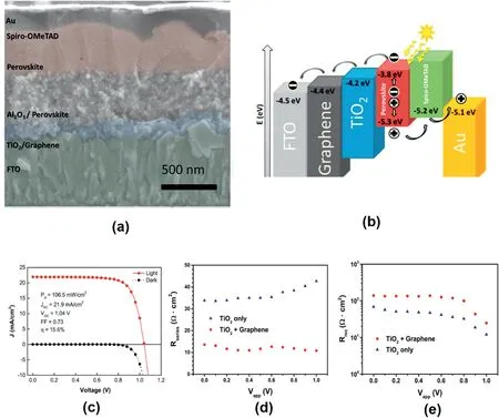
Fig.11.(a)Cross-sectional SEM micrographs with color-enhanced and annotated cross-section showing a general schematic of the solar cell architecture.(b)Schematic illustration of energy levels of the materials used in this study.(c)The best performing(η=15.6%)solar cell based on a graphene-TiO2nanocomposites under simulated AM1.5,106.5mW cm-2solar irradiation(solid line),and in the dark(dotted line),which processed at temperatures not exceeding150°C.(d)Series resistance,Rseries,and(e)recombination resistance,Rrec,obtained from impedance spectroscopy analysis of samples with two different concentrations of graphene mixed with TiO2in the electron collection layer[121].
However,it’s still not clear what the key influencing factors are regarding the performance of PSCs.Therefore,to develop new carbon CEs for PSCs and further study its mechanism in determining the performance is important[113,114].Hu and his co-workers made great efforts to this.They invented several unique types of3D carbon nanomaterials,namely,mesochannel carbon nanowalls(MCN)[80],three-dimensional honey-comb like structured graphene(3DHG)[115],and highly conductive Na-embedded carbon nanowalls(Na@C)[116].The synthesized carbon exhibited excellent performance as electrode materials in perovskite solar cells.Fig.10a shows the FESEM image of mesochannel carbon nanowalls.They proposed that a main reason for the low power conversion efficiency is the inefficient interface between the perovskite layer and the MCN counter electrode for hole extraction(Fig.10b).To improve the interface,MCN was introduced into the solution of perovskite precursors,followed by the in-situ synthesis of perovskite layer,leading to an enhanced PCE of10.43%(Fig.10c).Similarly,3DHG also exhibited excellent performance without hysteresis(Fig.10e).The IPCE curve of3DHG-based PSC shows a strong spectral response in the range from350to750nm(Fig.10f).The integrated current from the IPCE curve is consistent with the Iscobtained from the I–V measurement.Furthermore,invented Na@C materials,which possess ultrahigh conductivity and large accessible surface area,shows porous nanowall-like structure with thicknesses of about50nm(Fig.10g and h).This material exhibited excellent performance as a counter electrode for HTM-free PSCs(Fig.10i)and solved the contradiction between high surface area and high electrical conductivity[116].
Other research groups also made great effort in the carbon-based PSCs research area.Li investigated the possibility to use a mesoscopic TiO2/Al2O3structure as a framework and SWCNT-doped graphite/carbon black as CE material for PSCs.A PCE of14.7% was achieved for CH3NH3PbI3-based PSCs.This is attributed to the increased chargecollection for the PSCs with SWCNT compared with those without SWCNT additive[117].Bai fabricated simplified HTM-free PSCs with low cost carbon electrode where the insulation layer was removed.With the two-step spin-coating method,PSC based on MAPbI2gained a high PCE of12.49%[118].Zheng et al.designed the sol-gel process from which a mesoporous TiO2nanobowl(NB)array can be prepared.Furthermore,the pore size,bowl size and film thickness can be easily controlled by adjusting the diameter of polystyrene(PS)template.The carbon cathode-based PSCs show a higher PCE up to12.02%than that of the planar counterpart.This can be attributed to the enhanced light absorption with NB-assisted light management,improved quality of perovskite crystals,and better ability for electron extraction and charge transportation because of the increased interface contact[119].A mesoscopic PSC device using a quadruple-layer architecture,consisting of inorganic metal oxides in combination with carbon CE shows15.03%PCE under100mW cm-2[120].
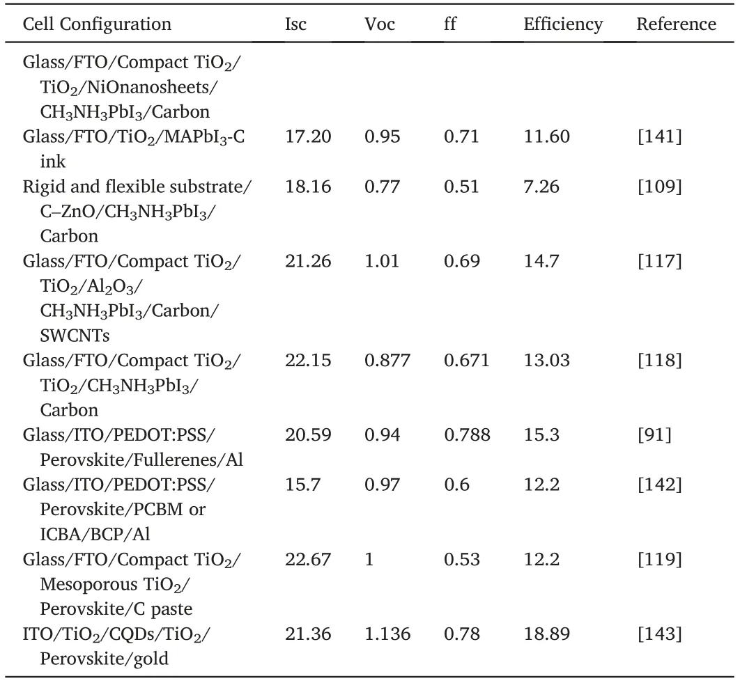
Table2(continued)
3.3.As electron transporting material
Carbon materials have been also investigated to improve electron extraction in PSCs as electron transporting material.In this case,carbon material should have the ability to collect electrons.Snaith’s and Nicholas’s group first demonstrated the usage of graphene as ETM in the end of2013.Graphene was introduced to overcome the intrinsic limitation of direct device architectures based on TiO2ETM[121].Fig.11a shows the color-enhanced cross-sectional SEM image of the device architecture while Fig.11b shows a schematic illustration of the device.A100nm thick TiO2/graphene composite was deposited from a thoroughly sonicated precursor mixture of both components in isopropanol,leading to a high PCE of15.6%(Fig.11c).The impedance spectroscopy(IS)results showed that graphene reduces the series resistance in the cell(Fig.11d)and increases recombination resistance(Fig.11e),consistent with that extracted from the J-V curves.This work provides a new strategy to intimate contact between TiO2and graphene,which further confirmed by the other researchers[122,123].Umeyama et al.proposed a similar strategy by systematically investigating the relation between the incorporated rGO in dense and mesoporous TiO2layer of PSCs[124].The device performance was enhanced from6.6% to9.3%,which is attributed to a reduced series resistance for the PSCs.Jun et al.also reported a PCE of14.5% by using rGO/TiO2paste[125].Furthermore,carbon nanotubes could also be introduced into TiO2to accelerate the charger transfer,illustrating the benefit of carbonaceous additives for electron extraction[126,127].
Besides TiO2,other metal oxide porous electrode have also been recently incorporated with carbon nanomaterials to form nanoporous ETM in PSCs,such as SrTiO3,which shows a perovskite crystal structure,demonstrates a high electron mobility,leading to an average PCE of10%[128].Table2summarizes the application of carbon materials in PSCs.
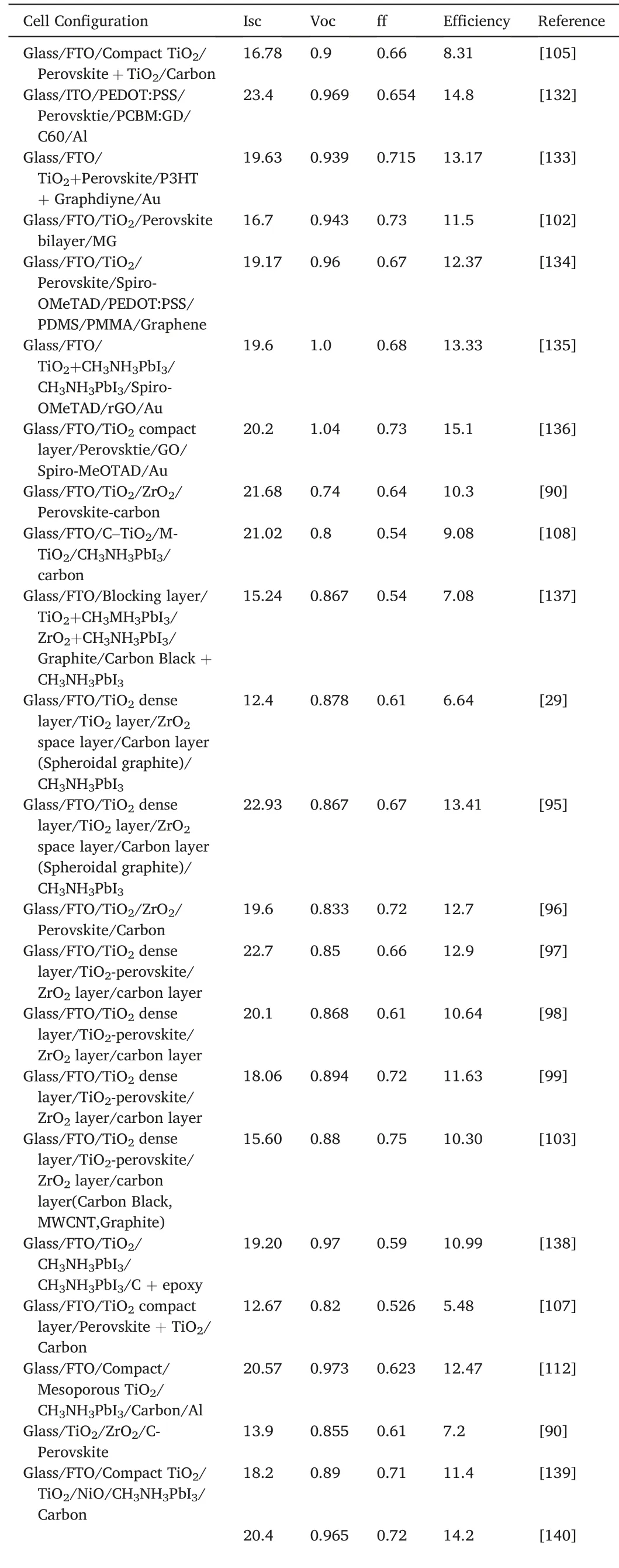
Table2 Summary of photovoltaic performance parameters of other carbon materialsbased perovskite solar cells.
4.Summary and outlook
Organometal halide perovskites are important photovoltaic materials which show great potential for next-generation commercial photovoltaic modules.To achieve future commercial applications,the efficiency and stability of PSCs have to be addressed.Carbon nanomaterials are promising candidates for addressing these issues due to their unique properties as well as low cost and abundance.
In this paper,the authors review the current progress on the applications of carbon-based nanomaterials in perovskite solar cells.Graphene and carbon nanotubes can enhance the charge transport,replace the traditional metal electrodes due to the excellent conductivity,and accelerate the electron transport.Furthermore,carbon-based PSCs exhibited long stabilities.However,there is still valuable and important work to be done to further improve the efficiencies and stability of the perovskite solar cell system.One possible area of research could focus on the vertical alignment of the carbon nanotubes with other materials in a device.This will maximize the benefits of fast charge carrier mobility provided by carbon nanotubes.Another interesting study may be to increase the hydrophilicity of graphene,which can improve the contact between the carbon electrode and perovskite layer.We will expect to see many more reports integrating carbon materials into PSC system over the coming years as the field rapidly evolves.
Declaration of competing interest
The authors declare no competing financial interest.
Acknowledgements
This work was partially supported by the ACS Petroleum Research Fund(PRF #59716-DNI10)and The Kansas NASA EPSCoR Research Infrastructure Development Program(#80NSSC19M0042).
杂志排行
Namo Materials Science的其它文章
- Quantitative kinetic analysis on oxygen reduction reaction:A perspective
- Synthesis of hexagonal boron nitrides by chemical vapor deposition and their use as single photon emitters
- Surface microstructure-controlled ZrO2for highly sensitive room-temperature NO2sensors
- Advanced carbon materials with different spatial dimensions for supercapacitors
- RTV silicone rubber composites reinforced with carbon nanotubes,titanium-di-oxide and their hybrid:Mechanical and piezoelectric actuation performance
- Hierarchically electrospun nanofibers and their applications:A review