Hierarchically electrospun nanofibers and their applications:A review
2021-11-16MuhmmdBdmusJingLiuWngNorertRdcsiYongZho
Muhmmd Bdmus,Jing Liu,NüWng,Norert Rdcsi,*,Yong Zho
a School of Engineering,Institute for Materials and Processes,University of Edinburgh,Robert Stevenson Road,Edinburgh,EH93FB,United Kingdom
b Key Laboratory of Bioinspired Smart Interfacial Science and Technology of Ministry of Education,School of Chemistry,Beihang University,Beijing,100191,PR China
Keywords:Hierarchical structures Electrospun nanofibers Hollow fibers Core-shell fibers
ABSTRACT
1.Introduction
Electrospun nanofibers(ESNF)account for about1000publications of all yearly nanotechnology studies since2014[1].This interest is partly due to the fascinating morphologies exhibited by self-assembled ESNF,leading to its uses in processes like drug delivery[1],filtration[2],and energy storage[3].They possess continuous elongated fibers at a high aspect ratio and a high degree of fiber orientation[4].Nanofibers can be fabricated by other methods like template synthesis,phase separation,melt blowing,and bicomponent extrusion[5].These techniques can make one-dimensional(1D)to three-dimensional(3D)fibers.Of all the available fabrication options,electrospinning is the simplest and cheapest one.
Despite the ease of conventional nanofibers,it is limited in some ways,in terms of the availability of polymer solution and using a more environmentally friendly solvent.Also,after post-processing,the as-spun nanofibers often have bald structures,thus incapable of various applications[6].Fortunately,through different fabrication techniques,novel hierarchical structures can alleviate some of these issues.
Hierarchical structures provide increased surface area,increased porosity,and good structural stability[1,4,7,8].Furthermore,some hierarchical structures exhibit anisotropic properties,hence have multifunctional capabilities[1].There are two classes of hierarchical structures discussed in this review:secondary and primary structures[4].Secondary structures include zero-dimensional(0D)nanopores,1D nanorods,1D nanopillars and two-dimensional(2D)nanosheets.They are typically grown through heat treatments,such as calcination and solvothermal reaction.ESNF serve as templates for the growth of these secondary structures.But there are many scenarios that they grow without the need of ESNF templates[9].Generally,secondary structures display morphologies below the3D,but their combination can inherently lead to a3D morphology.
Primary structures are fabricated via special electrospinning configurations,such as coaxial[10]and triaxial spinnerets[11],multiple feeds solutions[1],and special feeds,like block copolymers[12].One unique primary structure is the honeycomb fiber,due to its self-assembly nature and no requirement for a unique electrospinning setup,except for a restricted window of parameter[13].Other primary structures in this review include core-shell,hollow,side-by-side,and beads-on-a-string.In comparison to Wu et al.[2],these structures are less complicated.The study reported the fabrication of wire-in-tube fibers with three surfaces and tube-in-tube with four exposed surfaces.All of these structures were based on the hollow hierarchical structure.Other fascinating hierarchical structures include nanotubes,nanoflowers,and multi-unit structures like multichannel structure,peapod-like structure,etc.[14].
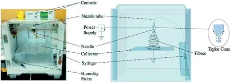
Fig.1.Illustration of conventional single-nozzle electrospinning.Adapted from Vong et al.[24].
Despite the increasing number of studies on hierarchical nanofibers,fabrication studies are limited.As a result,most research within this category focuses on the functionality of the fibers.Commercial businesses understand the benefits of monopolizing products of hierarchical nanostructures due to their apparent feature.With an improvement for large scale productions,some of the world's most critical problems can be solved.For example,tissue grafts can face issues of donor availability and morbidity[15].A potential solution is the use of an electrospun scaffold with hierarchical nanopores,which can mimic the extracellular matrix(ECM);the porous structure can provide access for cell migration,which can spurn tissue regeneration[16].Besides,according to the World Health Organization(WHO),29%of people do not have access to a clean water supply[17].Hierarchical structures such as nanosheets,nanopores have the ultra-filtering ability with high flux for clean water production[18].Thakur et al.[19]also utilized the beads-on-a-string structure for fog harvesting applications.Despite these breakthroughs,large scale production is an area for concern.
The focus of this review is on the fabrication techniques and applications of hierarchical nanomaterials via electrospinning.With the everincreasing interests in this field,the review will produce a highlight of limitations and future scope.
2.Electrospinning
Electrospinning dates back to1900,was previously known as electrospraying in the1890s[20].It is one of the simplest,cheapest,and fastest methods for fabricating solutions,melts,and suspensions into continuous fibers of nanoscale diameter.The traditional setup,as shown in Fig.1,requires a high voltage power supply,a syringe pump,a spinneret,and a collector(typically metallic)[21,22].The power supply,connected to the spinnerets,generates charges causing a potential difference across the solution[6,21,22].As a result,the solution l eaving the spinnerets,usually positively charged,repel at the spinneret's orifice.The accumulation of charges at the spinneret's tip leads to the formation of a conical-like droplet,known as the Taylor cone[6,21,22].Eventually,at a sufficiently high voltage,the electrostatic repulsion force overcomes the surface tension of the solution,and the resulting jet then witnesses instability due to the electric field,resulting in the elongation and evaporation of the solvent.This causes the jet to form continuous long fibers,which are deposited onto the oppositely charged collector.At a low electrical voltage,a phenomenon known as Rayleigh instability occurs,in which the solution breaks off into spherical droplets[23].Therefore,it is essential to operate at a high enough electrical field.
Feed conditions such as concentration and ambient conditions,like relative humidity and surrounding temperature,can affect fiber morphology.Another vital factor to consider is the deposition time.A short deposition time will ensure longer jet elongation and solidification,leading to a generation of longer and thinner fiber[6,21,22].However,increasing deposition time could also be done by increasing the distance from spinneret to collector,which can cause bending instability in the elongation process[23].A novel electrospinning process called near field electrospinning allows closer proximity between the collector and thespinnerets[25].This approach helps to remove bending instability and allows better control of the fiber deposition and morphology.Uematsu et al.[26]concretely analyzed the bending instability of an electrified thin jet during the electrospinning process by high-speed camera observation.Other parameters and effects,which affect fiber morphology in electrospinning are shown in Table1.
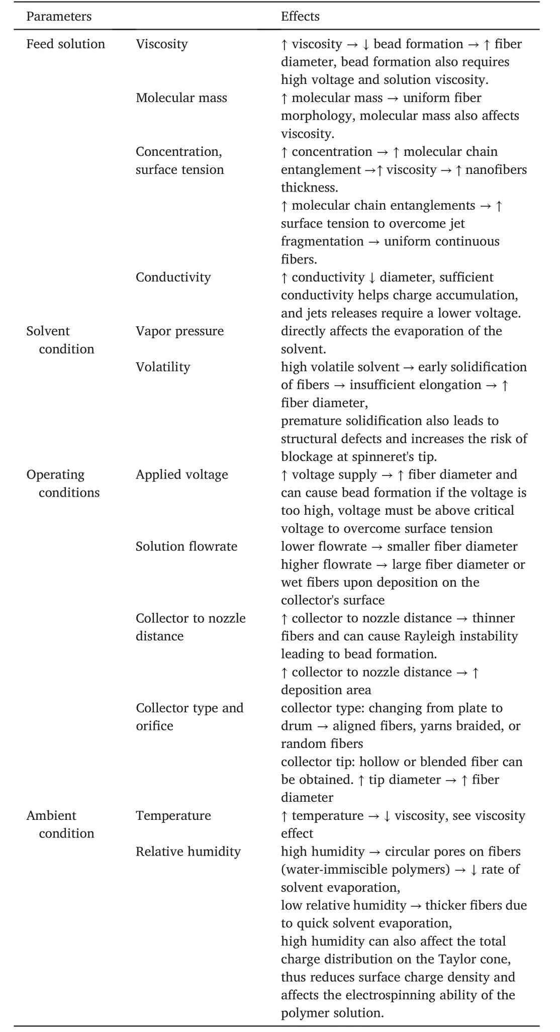
Table1 Parameters of electrospinning and their effects on ESNF morphologies[16,21],“↓,→,↑denotes decreasing,implies and increasing respectively”.
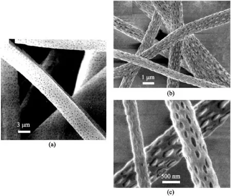
Fig.2.SEM micrograph of nanopore morphology(a)amorphous polycarbonate with circular pores typical of BF.(b)Poly-L-lactide(PLLA)in dichloromethane.(c)Magnification of micrograph(b).Reprinted from Wiley Publication[31].
3.Fabrication
3.1.Secondary structures
Secondary structures are attractive due to the variety of properties imparted on smooth fiber surfaces,which allow nanofibers different features like hydrophilicity,hydrophobicity,and ultrafiltration.They are generally prepared through a two-step process of electrospinning,followed by the post-process treatment of the fiber surface.An alternative to the two-step approach is the nanopore preparation method,where humidity or solvents are adjusted to get the desired pore morphology.Some studies have managed to fabricate multiple secondary structures on the same fiber template.However,this review will only cover nanopores,nanopillars,nanorods,and nanosheets.Some of the ideas for hierarchical structures are derived from nature,like nanopillars mimicking the surface structure of lotus and nanopillars contact splitting characteristics attributed to geckos[4,27].Some of the structures are also similar due to the nanopillars,nanorods,and nanorods sitting perpendicular to the electrospun surface.This can be important for imparting anisotropic property to the structure.Nanopores,however,can possess both internal and external pore structure depending on the desired application.The characterization of secondary structures is mainly by transmission electron microscopy(TEM)or scanning emission microscopy(SEM).Depending on the desired applications,specific tests are required.For example,a pH sensitivity and wettability test would be required for applications in drug delivery and water harvesting,respectively[2,28].
3.1.1.Nanopores
It is a general understanding that to create porosity in fibers,the selection of the polymer/solvent and the control of temperature and humidity are essential.The effect of polymer/solvent has generated some contrasting views from different studies.Using volatile solvents such as dichloromethane(DCM),acetone(AC),and chloroform(CHL)on a poly(lactic acid)(PLA)polymer,Tan et al.discovered no pores on PLA fibers from using DCM solvent[29].And studies that were done by both Casasola et al.[30]and Bognitzki et al.[31]reported pore formations using DCM solvent and PLA polymer.Another study by Li et al.[32],using AC solvent,found no pores on the PLA fibers.Interestingly,a study by Branciforti et al.found pores by mixing both AC and DCM as a binary solvent for electrospinning PLA[33].
Bognitzki et al.[31]also investigated three different polymers:semi-crystalline poly-L-lactide(PLLA),amorphous polycarbonate(PC),and polyvinylcarbazole.All three were dissolved in DCM,showing successful pore formation.This study was the first to recognize polymer-solvent phase separation as the main reason for pore formation.Recent studies,particularly after2015,have also been very successful in forming pores on PLA fibers by taking account of the polymer/solvent composition and sometimes using a polymer/solvent/non-solvent mixture.However,some of the most electrospinnable fibers might not produce porosity under this theory.It is also still unclear as to why polymers in Bognitzki et al.[31]study displayed different pore shapes or if the same scenario would occur in other polymer-solvent configurations.Hence,Huang et al.[34]study delved into binary or ternary phase diagrams,which shows phase boundaries as a function of temperature and composition of suitable solvent mixtures for pores formation[34].These phase separation diagrams then depend on if the desired separation is:(1)Non-solvent induced phase separation(NIPS);(2)Vapor induced phase separation(VIPS);(3)Thermal induced phase separation(TIPS)and;(4)Breath figure(BF),perhaps the easiest of the mechanisms.
Pores formed through BF possess circular pores(Fig.2a).Most studies comment on these pore shapes but rarely explain the reason behind this.
BF mechanism is a condensation of water vapors on the surface of the fiber jets.Eventual evaporation of droplets leads to circular pore formation[34].The pore shape occurs due to its formation after the fiber's electrospinning,where thinning and elongation occurs,thus preventing an elliptical pore shape[35].Surface pores on NIPS and VIPS have an elliptical shape[34,35].Surface porosity particularly prefers hydrophobic polymers such as polystyrene(PS),poly(methyl methacrylate)(PMMA),and PLA[34].However,the solvent choices are limited,but the commonly used ones are DCM,CHL,and THF[34].
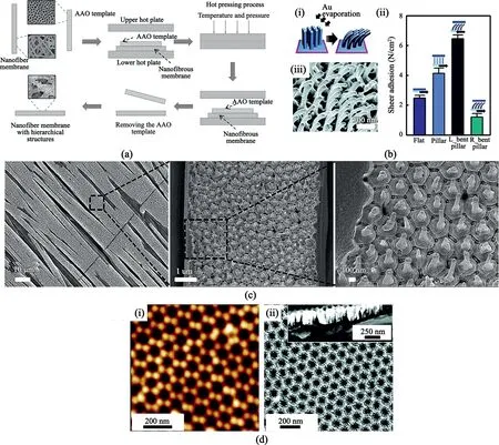
Fig.3.Nanopillars fabrication and morphology.(a)Illustration for nanopillars fabrication using the AAO template.Reprinted from Wiley Publication[28].(b)Uniformly bent Janus nanopillars and its shear adhesion force comparison of the Janus nanopillars.(i)Effect of gold(Au)on nanopillars.(ii)Bending characteristics of nanopillars due to Au at500nm scale(iii)Shear adhesion vs.surface characteristics of polyurethane acrylate(PUA).Flat means the absence of nanopillars on the surface,L_bent,R_bent means left and right bent nanopillars,respectively.Reprinted with permission from Choi et al.[45]Copyright(2011)ACS Publication.(c)SEM images of hierarchical PMMA structure after annealing at150°C for18h.Reproduced from Sahay et al.[41]with permission from RSC Publication.(d)AAO membrane(i)SFM image of AAO membrane.(ii)SEM image of the AAO membrane.The inset shows the side view of the membrane.Reprinted with permission from Chen et al.[44]Copyright(2012)ACS Publication.
Furthermore,a study by Huang et al.[35]investigating porous PLA reported the trends in pore shapes due to the change in the composition of non-solvent during NIPS.In a ternary mixture of PLA/CHL/Ethanol(EtOH),where CHL is the solvent and EtOH is the non-solvent.It should be noted that EtOH is miscible with water as opposed to the requirement in Table2,and EtOH's influence on pore structure is due to its water-miscibility property.Like other NIPS mechanisms,a highly volatile CHL solvent evaporates much faster than the lesser volatile EtOH,causing the mixture to enter a ternary phase,with an increase in EtOH.In their study[35],an increase in the solvent composition from95/5(CHL/EtOH)to10%and further,shows a structural pore change from a porous surface to scalloped and to smooth fibers with few wrinkles.The miscibility of EtOH allows water droplets(condensed due to CHL evaporation)to spread over the fibers causing wrinkling on the fiber surface overtime.This study is the first that provided details on pore structural change.When EtOH was replaced with dimethyl sulfoxide(DMSO),the observed pore change was from elliptical surface pore(Fig.2b and c)to non-porous fibers with wrinkles.Increasing the composition further leads to an internal pore formation with hollow PLA fiber.This difference is primarily attributed to the volatility difference(boiling point:DMSO 189°C,EtOH78°C).

Table2 Solvent characteristics for different phase separation mechanisms.The porosity,advantages,and disadvantages are also included[34,35].
Many studies combine the TIPS and NIPS mechanism(N-TIPS).TIPS is a rapid decrease in temperature of as-spun fibers,which were initially at an elevated temperature.This process requires a low-temperature collector like a liquid nitrogen bath;this is an energy-intensive process hence justifies its combination with the NIPS mechanism[34].Kim et al.[36]mentioned that TIPS is expected to affect the fiber support,while NIPS affect surface morphology(pore).The review then claimed later that the rate of mass transfer(of the solvent),which affected NIPS morphology and polymer solidification(dependent on the TIPS),both relied on the system temperature.This claim is compared to a study conducted by Li et al.[37]in which water was both the cold collector bath and the non-solvent.In this mechanism,water-miscible non-solvent is preferred.The results from the study indicate that the eventual evaporation of water vapor after the fiber had frozen led to pore formation.However,fiber morphology was due to TIPS.In another study done by Matsuyama et al.[38],both NIPS and TIPS were independently controlled using different bath media of water and methanol.One would see that the ratio of solvent/non-solvent affects the polymer concentration,which affects fiber structure.Therefore,since the solvent/non-solvent ratio is controlled by temperature,it can be concluded that system temperature is the primary determinant for N-TIPS pore formation.In situations where nanopores are undesired,a freeze-drying approach is used.It is a more complex process as it requires freezing solidification of the fibers scaffold in a cold bath(e.g.,nitrogen bath),followed by sublimation from solid to a gaseous state and then vacuum drying[39].This process leads to large pore formation,with an added benefit for producing3D scaffolds.
Another major factor to consider for pore formation is the relative humidity.Uniform fibers are normally observed at a low relative humidity below16%[31,40].Studies have often reported pore formations from humidity within the range of30%–70%[31,34,40].The diameter of the nanopores typically observed in this range is between48nm and 140nm(in PS polymer dissolved in THF/DMF solvent),with respect to increasing humidity[31,40].The impact of humidity is due to its relationship with solvent evaporation which affects the surface charge of the electrospun fiber.Besides,as the electrospinning temperature increases,porosity becomes less likely,hence humidity and temperature are crucial for successful pore formation.
3.1.2.Nanopillars
Most studies conducted on the fabrication of1D nanopillars focuses on the technique of electrospinning combined with the template-wetting method.The electrospun fiber is considered the first level of the hierarchy and does not require a special electrospinning setup.The second hierarchy level is the nanopillars,which are most commonly fabricated using anodic aluminum oxide(AAO)templates(shown in Fig.3a).However,there are other methods like nanomachining[41],lithography[41],and chemical deposition[42],all with their benefit,but none as simple as AAO template deposition.
The prevalence of AAO template deposition was established by Mijangos et al.[43]by giving five reasons why AAO might have generated such interest as a template:
a.Pore diameter can be used easily to adjust the“degree of confinement”of polymers.
b.The monodispersed,cylindrical pores and the rigid pore walls present a very well-defined geometry for confinement.
c.AAO templates have high pore densities(109–1011pores cm-2)with a high aspect ratio greater than104possible.
d.The high surface energy of the hydroxylated pore walls enables simple impregnation of polymers as well as the ultra-high aspect ratio pores.
e.Most polymer processes occur below500°C.This temperature range is suitable for AAO as it can stay inert and stable.
Before going further,nanopillars grown by AAO are established by the following steps(Fig.3a)[28]:(1)the preparation of the AAO template,followed by;(2)the sandwiching of the ESNF in the AAO template;(3)then the nucleation of nanopillars by heat treatment;(4)and finally,removing the AAO plates from the nanopillar nanofibers,which can be complicated.An easy peel-off could be done but is dependent on the type of material or polymer;thus,more extreme measures are sometimes taken.This was seen from Wei et al.[44]where poly(3-hexylthiophene)(P3HT)was dissolved in NaOH/water solution,and after freeze-drying,water was removed under high vacuum conditions.A heating treatment on the P3HT dissolved in NaOH/H2O would have poisoned the P3HT and destroyed the nanopillar.
Nanopillars can have a vertical uniformly distributed pillar or round base with a hemispherical top,as shown in Fig.3c.Moon et al.[45]reported a method for controlling nanopillar size by varying the interpore distance,aspect ratio,and diameter of the AAO template.Poly(-dimethylsiloxane)(PDMS)was used to treat the surface of the AAO,which then lowered the surface energy inside the AAO pores.This treatment weakened the adhesion force between the AAO mold and the polymer.Resultantly,nanopillars with a high surface ratio were produced.
Another great benefit offered by PDMS is the reusability of the AAO template for more than100times,making it very cost-effective.The reusability was due to the rigid structure of PDMS,hence,limiting the damage on AAO templates.Sahay et al.[41]reported increasing the temperature and prolonging the time of annealing to improve the height of nanopillars,while Mijangos[43]suggested changing the electrolyte used in AAO preparation.This influenced the template thickness and indirectly affected the pores and nanopillars'diameter.The unique characteristic was the bending of nanopillars employed by Moon et al.[45],which used metal(gold or aluminum)deposition on the nanopillars(Fig.3bi,3biii).The asymmetrically bent nanopillars were known to have high anisotropic shear adhesion and directional wetting characteristics[45](Fig.3bii).Mijangos et al.[43]developed a table detailing polymer and infiltration conditions(including required AAO diameter/length)for the appropriate preparation of the AAO template(AAO template shown in Fig.3d).
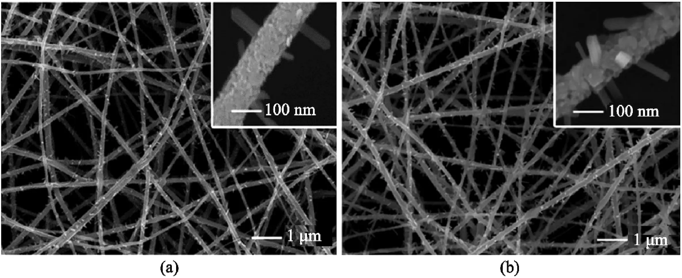
Fig.4.SEM image of V2O5nanorods on electrospun TiO2nanofibers.The calcination temperature is475°C for a different time:(a)10min and(b)60min.Insets show magnification at100nm.Reprinted with permission from Ostermann et al.[47].Copyright(2006)ACS Publication.
Due to the adhesive property and water harvesting characteristics of the hierarchical nanofibers(nanofibers with nanopillar surface),its effect is often compared to neat electrospun fibers(with no nanopillars).Ganesh et al.[28]compared neat nanofibers,electrospun nanofibers loaded with microparticles,and hierarchical nanofibers with the ability to retain water.The latter showed a higher water contact angle and lower hysteresis compared to the rest.This is attributed to its high surface roughness and low surface energy.For its use in dry adhesives,electrospun fibers have a high surface area,and this level of the hierarchy is controlled directly by electrospinning while the second hierarchy level(nanopillars)is controlled by the AAO template[27].In addition,the hierarchical nature mimics the contact splitting nature of seta(in geckos)[27].These characteristics help in retaining an excellent and better adhesive property when compared with neat nanofibers.
3.1.3.Nanorods
Nanorods have a unique1D hierarchical structure compared to nanopores,and nanopillars,because they are generally electrospun from the metal oxides and chlorides etc.,instead of polymers.One rationale behind this could be due to their uses for battery[46,47]and capacitors,hence,the need for conducting materials.Another unique feature of nanorods is the different fabrication techniques employed by various studies.For example,Bai et al.[48]produced the gold(Au)nanorods on a homogenous electrospun polyacrylic acid(PAA)/polyvinyl alcohol(PVA)fiber by initially preparing the Au nanorod solution by seed-mediation and immersing the PAA/PVA into the solution,which then underwent a heating treatment for12h.This approach considers a two-step fabrication.
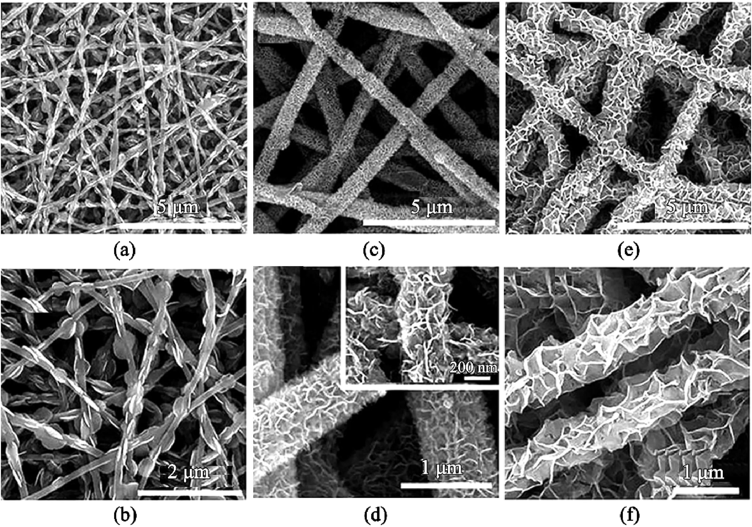
Fig.5.SEM images of bismuth nanosheet grown on electrospun carbon nanofibers(ESCNF),the composition of bismuth was increased by increasing Bi2O3 concentration in an order denoted by0.5,1,and2.(a and b)ESCNF@Bi2O3-0.5,(c and d)ESCNF@Bi2O3-1(the inset in(d)shows the high magnification view),and(e and f)ESCNF@Bi2O3-2.Reproduced from Li et al.[54]with permission from RSC Publication.

Fig.6.Illustration of nanosheets morphology change due to an increase in calcination temperature.Reproduced from Tian et al.[3]with permission from RSC Publication.
In contrast,both Cherian et al.[47]and Ostermann et al.[49]uses heat treatment to facilitate the growth of nanorods on electrospun fibers.Cherian et al.[47]synthesized α-Fe2O3nanorod by the annealing of electrospun polyvinylpyrrolidone/ferric acetylacetonate(PVP/Fe(acac)3)composite precursor at500°C for5h.Ostermann et al.[49]also carefully calcined composite nanofibers consisting of amorphous V2O5,amorphous TiO2,and PVP for the growth of single-crystal V2O5nanorods.The control on temperature and time for this heat treatment is very crucial and often depend on the electrospun material.As shown in Fig.4a and b,the height of the nanorods is different at the same temperature,and different heat treatment duration.A unique fabrication was done by Sun et al.[50],following the fabrication of TiN nanorods from a mixture of dimethyl formamide-ethanol,PVP,and Ti(IV)-isopropyl-oxide.The as-spun nanofibers underwent calcination and converted conversion into TiO2nanorods.A fascinating part of this was the complete conversion of the TiO2nanofibers into TiN short nanorods,the length of which depended on the nitridation temperature.
Research on understanding nanorods morphology is limited,as various studies tend to focus on its benefits concerning desired applications.Nonetheless,it is generally understood that nanorods are anisotropic,which makes it essential for practical application.Au nanorods,for example,is used widely for optical applications and can support plasmons in both the transverse and longitudinal direction[51].It should be noted that the anisotropic property is influenced by the aspect ratio,of which length is affected by the annealing or calcination temperature.Lower temperature favors thinner and uniform nanorods,while the high temperature is more likely to form shorter and thicker nanorods[48,49].
3.1.4.Nanosheets
One of the attractive qualities of2D nanosheets is its ultrathin structure,as shown in Fig.5.These2D hierarchical structures can be used in photocatalytic,supercapacitors,and battery applications.Nanosheets can be produced independently without the need for electrospun materials template and thus can be created via exfoliation,surfactant-assisted synthesis,modulated synthesis,and sonification synthesis etc.[9]However,this section will focus on the fabrication of nanosheets via two steps:electrospinning of the fiber template followed by solvothermal or hydrothermal reaction with nanosheets material.Also,most studies have mainly adopted the use of metal dichalcogenide(e.g.MoS2,TiS2,TaS2,and WS2)[52],and semiconducting metal oxides(SMOs)for the fabrication of nanosheets[53].
Nanosheets,typically grown on nanofibers due to the added benefits of increased surface area,high structural integrity,and good electrical conductivity,were prepared with varying concentrations for sheet uniformity and structural stability(Fig.5a–f).For example,Zhang et al.[55]produced varying concentrations of WS2/GCNF(namely,WS2-1,WS2-2,and WS2-3)from(NH4)2WS4(5mg,10mg,20mg;each corresponding to WS2-1,WS2-2,and WS2-3respectively)dissolved in20mL dimethylformamide(DMF)solution.WS2-2was found to be the best optimum,contrary to the expectation that WS2-3will provide the best structural stability due to its high concentration.The lowest concentration,WS2-1,had too little flake,while the WS2-3layer was too thick and had formed spherical agglomerates.Unfortunately,agglomeration was a characteristic of most nanosheets fabrication.Figs.5and6illustrate this example but with varying concentrations of Bi2O3and NiMnO,respectively.Both Wang et al.[56]and Zhang et al.[55]reported that bare nanosheets also suffer from agglomeration,and the addition of a nanofiber template of enough diameter was useful for dispersing the nanosheets.
Some papers also reported the formation of core-sheath fibers after an increase of the growth of nanosheet on the nanofibers[54,57].Mingyi et al.[54]reported that an increase in Bi2O3nanosheet on electrospun carbon nanofibers(ESCNF)led to a perpendicular growth on the surface.The nanosheets were interconnected to form channels in the Bi2O3sheath layer,as shown in Fig.5.The channel and layer were sometimes responsible for some of the properties found on nanosheet-on-nanofibers structure.These included better ions,electron transport,and volume variation[3].Another critical factor to consider for the growth of the nanosheet is the solvothermal/hydrothermal reactions.
As expected,the duration and temperature at this stage affect the formation of nanosheet.Studies compared so far only researched the effect of temperature on nanosheet appearance.A contrasting study done by Li et al.[53]investigated electrospinning parameters on the presence of nanosheets.The study found that at a sufficient flow rate and needle-collector distance,nanosheet would appear.Otherwise,only rough surfaces on the nanofiber would appear.
Secondary structures mainly include0D nanopores,1D nanorods,1D nanopillars,and2D nanosheets,enhanced the application functionality compared with pristine fibers.Multi-pores on nanofibers produced extra internal surfaces,which helps better the use of the inner space of nanofibers.The formation of pore structure is mainly related to polymer,solvent,humidity,and processing temperature.The other secondary structured nanofibers,such as nanorods,nanopillars,and nanosheets attached to the outside of the fibers,enriched the composition of the nanofiber.These unique multilevel structures formed heterojunction on the nanofibers,which helped change the mechanical or chemical properties.Generally,hydrothermal or solvothermal were the most commonly used method to generate the heterogeneous structure on the outer surface of the nanofiber template.
3.2.Primary structure
Unlike secondary structures,primarily structured fibers are prepared via one-step electrospinning.They are produced either through specific feed requirement or adjustment of electrospinning parameters,e.g.,spinnerets or feed conditions.The configurations for primary structure can often be more complicated as studies aim to counteract the effect of charge repulsion in multipolymer feed solutions or reduce the charge effect of collectors to assist multilayering of fibers.One advantage of multipolymer feed is the ability to use a weak electrospinnable solution for at least one of the feed solutions.Feed solutions,especially for hollow fibers fabrication,can be doped with nanoparticles to help with applications like catalysis.As expected,the focus of most studies is to investigate their functionality due to the number of possible distinct morphologies.The primary focus of this section is on core-shell fibers,side-by-side fibers,honeycomb,block copolymers,and beads-on-a-string fibers.Like some secondary structures,primary hierarchical structures can be modeled after nature.For example,the honeycomb morphology relates to the bee's pollen storage architecture,and the spindle knot of beads-on-a-string mimics a spider silk[2,4].Improvement in primary structures formation can lead to an indirect improvement in traditional electrospinning since most innovation for fabricating primary structures are affected through feed types and electrospinning parameters.Characterization is predominantly done via SEM or TEM with an appropriate functionality test done depending on the desired application of the structure.

Fig.7.Electrospinning and SEM images of core-shell and hollow fibers(a)formation of core-shell fibers using coaxial needles.Reproduced from Qu et al.[58]with permission from RSC Publication.(b)SEM image for core shell fibers.Reproduced from Wu et al.[2]with permission from RSC Publication.(c)TEM image of a continuous core-shell fiber.Reproduced from Wu et al.[2]with permission from RSC Publication.(d)SEM of hollow fibers.Adapted from Lee et al.[65].
3.2.1.Core-shell fibers
Core-shell fibers account for about5% of all nanofibers publications[1].This is due to their application in the drug delivery field,which is a crucial aspect of human need.There are mainly four popular methods for producing core-shell fibers:template deposition,electrospinning of immiscible polymer blends,emulsion electrospinning,and coaxial electrospinning(Fig.7a).The middle two listed only requires a single nozzle.Template deposition will not be covered here,but it typically involves the deposition of shell materials on a ready-made fiber template via chemical vapor deposition,plasma,or sol-gel coating methods[58].
Unlike emulsion and coaxial electrospinning,the immiscible polymer blend is the least reported.Although polymer blend is regularly electrospun,it is typically not for core-shell formation.Besides,parameter conditions are too restrictive for core-shell[59].Zupancic[1]described the process as follows:at the tip of the nozzle,the inner polymer droplet is covered by the continuous phase polymer.Under high electrical charge,the continuous phase engulfs the inner polymer drop(usually the more viscous phase)and forms a core-shell jet.Additionally,polymers must have low molecular weight and be thermodynamically incompatible.Examples of polymer blends electrospun into core-shell include poly(methyl methacrylate)(PMMA)/polyacrylonitrile(PAN),polystyrene/PMMA[60]dissolved in dimethylformamide(DMF)[61]and tetrahydrofuran(THF)[60]respectively.
The electrospinning setup for both emulsion and polymer blend is the same as a traditional setup.Complexity in coaxial setup results in the prevalence of the emulsion approach,despite coaxial electrospinning having more precise control of encapsulated agents’location(e.g.,drugs)within its core[62].Coaxial electrospinning,first carried out by Loscertales et al.[58]in2002,required concentric spinnerets in the same axial direction;outer and inner spinnerets contains the shell and core fibers,respectively[1,63,64].Compared to the other approaches,coaxial electrospinning can be modified in terms of polymer solutions or the setup.In terms of the setup,Lee at al.[65]removed the exit pipe of the core,which allows the envelope of the core by the shell into a core-shell jet leading to a core-shell structure seen in Fig.7b and c[2].This configuration enables better core stability,as better interaction between the surface tension and charge accumulation as opposed to conventional electrospinning.
Coaxial core-shell is sometimes converted into a hollow structure for use in applications like catalysis.The removal of the core fibers after calcination usually results in the desired hollow structure,as shown in Fig.7d.One approach to get this is through the introduction of mineral oil.Zhang et al.[66]introduced mineral oil into the core nozzle of a coaxial setup,while the shell side polymer was a blend of phosphomolybdic(PMoA)and PAN.The hollow structure was obtained by first electrospinning the oil and PMoA/PAN into core-shell(oil@PMoA/PAN),followed by oil extraction of the core.As a result,hollow PMoA/PAN was obtained.After further decomposition of PMoA into Mo2C and PAN into C,another core-shell fiber of Mo2C@C was achieved with a unique hollow structure(Fig.7d).This structure provides a two-in-one property,as the hollow structure provides a high surface area for ion transfer(dependent on application),and the core-shell can be used to embed the desired material.Nanopore formation(discussed in nanopores section)through a non-solvent induced phase separation led to a hollow structure.As reported by Huang et al.[35],due to the low volatility and water-miscibility of the DMSO solvent,there was enough time for water to penetrate through the fiber surface,creating internal pores that eventually led to a hollow structure.
Emulsion electrospinning is a novel approach,which is more prevalent and stable than coaxial electrospinning[67,68].The reason for the prevalence,according to McClellan[62],is due to the possible solvation of protein within the mild solvent and the ability of the solvent to dissolve the desired polymer.Emulsion electrospinning minimizes the use of hazardous organic chemicals and accommodates the employ of water,hence its prevalence in the food and drug industries[62].Emulsion,like an immiscible polymer blend,is a mixture of two or more immiscible liquids,except one liquid is dispersed in another liquid of a continuous phase.
Contrary to initial remarks,Zhang et al.[68]reported that emulsions were thermodynamically unstable.However,following the addition of stabilizers such as emulsifiers and thickeners to emulsions pre-electrospinning,long-term stability can be ensured[1,59,64].
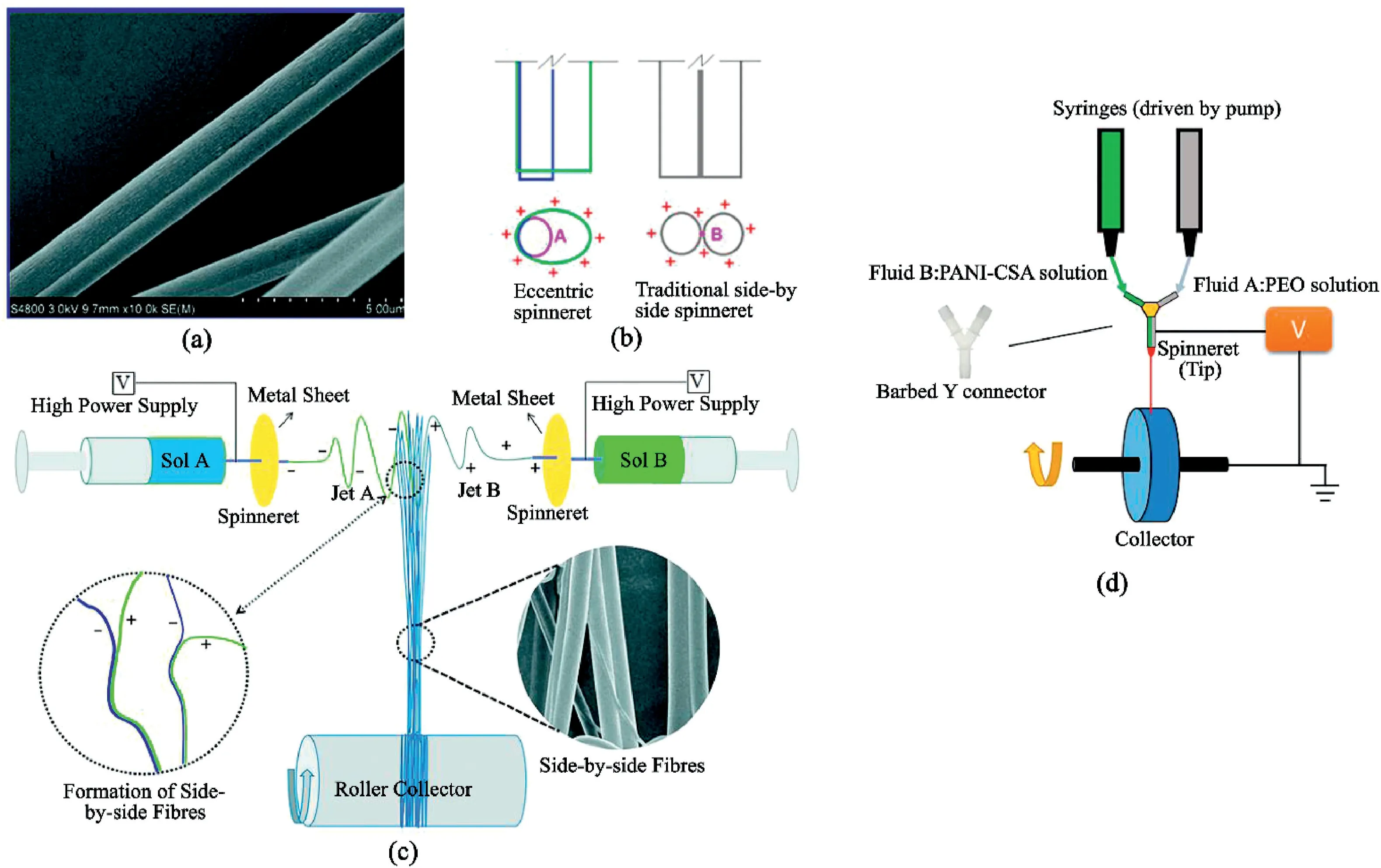
Fig.8.Illustrations of side-by-side fiber(SBS)and different setups:(a)SEM of a typical SBS fiber.Reproduced from Chang et al.[72]with permission from RSC Publication.(b)Influence of charges on working fluids in an eccentric and traditional side-by-side spinneret.Reprinted with permission from Wang et al.[73]Copyright(2018)ACS Publication.(c)Conventional SBS setup with the addition of a metal sheet inducing oppositely charged solutions.Reproduced from Chang et al.[72]with permission from RSC Publication.(d)Illustration of the attachment of a barbed Y-connector for contacting the two solutions before spinning.Adapted from Liu et al.[74].
Both traditional and emulsion electrospinning has the same setup and similar limiting parameters,but we still need to account for the complexity of the liquid interface,such as surface tension.Emulsion coreshell is typically generated due to the rapid evaporation of the solvent close to the surface,causing an increase in viscosity[67,68].This induces an inward movement of the emulsion droplet into the center as the condensation of the droplet occurs.The jet then stretches into an elliptical shape in the axial direction due to the presence of a high-voltage field.The presence of surface tension,gravity,and viscoelastic forces contribute to the contraction of the charged surface to minimize the interface area between the air and jet.Finally,on the collector surface,following rapid solvent evaporation,the droplets merge,forming a column-like structure then finally a core-shell structure.The core is formed by the dispersed phase[1].
One of the main problems associated with core-shell fibers is the electrospinning ability of the solutions involved.For emulsion electrospinning,Zupancic reported that the formation of core-shell did not depend on the spinnability of the dispersed phase,but instead,the continuous phase must be electrospinnable[1].Unlike coaxial core-shell,there is no consensus on the required electrospinning ability of both solutions[64].However,some studies do believe that coaxial electrospinning can be used for core materials(such as nonpolymeric Newtonian liquids),which cannot form nanofibers[64].In addition to the spinnability of fibers,an appropriate concentration of shell and core must be considered for the shell to engulf the core to achieve fiber uniformity.Unlike the immiscible polymer blend,long sections of the fiber can occur without a core[1,58].Solvents used are also an important consideration,particularly for coaxial core-shell fibers.Generally,studies have preferred solvents capable of dissolving both polymer solutions.However,a different solvent can be assigned to each polymer solution,but this solvent used must be chosen reasonably to optimize polymer solution and jet formation[1,63].All other limiting factors share similarities with conventional electrospinning.
3.2.2.Side-by-Side fibers
Side-by-Side(SBS)ESNF is an alternative to coaxial core-shell fibers in terms of multifluid feed[69,70].As its name suggested,SBS fibers are two-in-one fibers with both surfaces exposed to the environment(Fig.8a).They are fabricated similarly to conventional electrospinning but requires the use of side-by-side spinnerets for the different solutions.Unlike other nanofibers fabrication,SBS electrospinning is rarely studied despite some of its distinct advantages.These advantages include the ability to create different surface chemistry(such as both hydrophilic and hydrophobic surface in the same fiber),easy controllability over drug loading dosage,and co-culture of different cells[71].However,a reason for its rareness is due to problems with the conventional fabrication and modifications proposed by other studies can be too cumbersome to produce.
The main problem with conventional SBS electrospinning is the repulsion of the two solutions due to having similar charges[70,75].Therefore,modifications to SBS electrospinning attempt to prevent this issue by manipulating the charge effect of the solutions.A simple solution is the use of Teflon coating on the spinnerets,or eccentric spinnerets(Fig.8b).As expected,the Teflon coating aims to ensure the polymer solutions converge and form an integrated Taylor cone.Yu et al.[76]reported some additional benefits of Teflon-coating:(1)even charge distribution around the spinnerets;(2)the non-conductive nature of Teflon ensures efficiency in directing charge to the working fluid;(3)the non-sticky nature of Teflon prevents the nozzle from clogging.
Another modification suggested by Chang et al.[72]is the attachment of a metal sheet to the spinnerets,creating a2D auxiliary electrode plate(Fig.8c).This forms opposite charges between the jets and allows the jet stream to merge before fiber formation.Compared to configurations leading to an even distribution of similar charges across both spinnerets(e.g.,Teflon-coated spinnerets),solvents evaporate from the jet streams jets charges are dissimilar.As a result,the mixing of the jets leads to partially solidified SBS fibers,thus preventing complete mixing of the fibers.Chen et al.[70]also reported that increasing port angles of the spinnerets decreased the repulsion of the jet charges,and thus interfaces between fibers becoming vague.
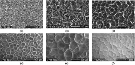
Fig.9.Self-assembly of electrospun fibers into honeycomb structure as a function of deposition time at PCL13wt%PCL,Vneedle=10kV and Vcollector=-10kV.SEM images at(a)t=30s,(b)t=2min,(c)5min,(d)t=10min,(e)t=60min,and(f)t=120min.Reproduced from Ahirwal et al.[13]with permission from RSC Publication.
The two studies compared here referred to the spinnability of the fibers.However,they both require a slight adjustment to the configurations.Another study by Liu et al.[74]is the successful use of the barbed Y connector(Fig.8d).The top mouths of the Y-connector were attached to the two-nozzle tip injecting the polymer solutions.This setup allowed a quick mixing of the two solutions at the lower tip of the Y.One of the polymer solutions must be spinnable.Wang et al.[73]also designed eccentric spinnerets,capable of overcoming the poor spinnability of one of the polymer solutions.An additional benefit of using eccentric spinnerets is that both polymer jets carry the same electrostatic charge,and no jets repulsion occurs.However,in both configurations,it is too complex to control the mixing of the solutions,but the diameter of the fiber can be affected by changing the flow ratio.
3.2.3.Honeycomb structure
The honeycomb structure is like a bee's architecture for the storage of pollen[77].This structure is composed of self-assembled fibers of highly ordered hexagonal units.Its self-assembly nature indicates it requires no unique or complex setup.The self-organization nature also makes it possible for3D scaffolds fabrication,provided the deposition time is appropriate.Many studies have attempted the fabrication of3D scaffolds via the self-assembly nature of the honeycomb structure due to its relative simplicity.Most of these studies affect scaffolds thickness by using patterned collectors.
The consensus by researchers is that the electric field force is the most decisive factor for obtaining honeycomb network fibers[4,77,78].Nedjar et al.[78]reported a bimodal size distribution of polycaprolactone(PCL)fibers as a result of the heterogenous dissipation of electric charges.The electric field causes the formation and distortion of the micro-sized droplet,and the resulting phase separation and energy minimization cause the hexagonal structure[4].As shown in Fig.9,there are thick fibers distributed across the network border,while the thinner ones are formed across the network[13].This is due to the distorted electric charges.Other limiting factors include concentration,working distance,and deposition time.
Liang et al.[79],however,claimed that there were very few studies on ambient conditions affecting honeycomb formation.Examples of these include relative humidity(RH),atmospheric temperature,and gravity.So far,all the factors listed are also considered during conventional electrospinning.As investigated by Liang et al.[79],the diameter of the fibers was similar when RH was varied between53% and93%.This range produced3D honeycomb structures,but below73% RH,the patterns generated were not well defined.Medeiros et al.[80]reported a thinner diameter in PVA by decreasing RH,while Hardick et al.[81]reported a higher diameter when increasing both RH and atmospheric temperature.From the three studies compared,only Liang et al.[79]reported the formation of a honeycomb network due to humidity,while the latter two studies only reported the morphological changes after fiber formation.
Liang et al.[79]also reported the appearance of bead formation with an increase in RH.Most honeycomb structures observed contains bead formation.Unsurprisingly,this is due to the low concentration requirement for honeycomb appearance.A study done by Yao et al.[82]reported that18wt%PCL led to the formation of a honeycomb pattern but also produced many beads.In contrast,Ahirwal et al.[13]fabrication of honeycomb at13wt% PCL produced no bead at13wt% PCL(Fig.9).Fig.9a–f,from the same experiment,also revealed that the diameter of the honeycomb increases with electrospinning time.In Yao et al.[82]experiment,the disappearance of beads only occurred when the concentration was increased to22wt%,with improvement in viscosity and smoother honeycomb patterns.Increasing the concentration further to 26wt% meant the disappearance of self-assembly,but no honeycomb pattern was observed.Since beads possess large diameters,they are expected to be seen at the border of the honeycomb network.
The self-assembly organization of honeycomb is one of the easiest methods of fabricating3D scaffolds.The scaffolds can be essential in tissue engineering,as scaffolds resembling the ECM can be produced.However,the mechanical strength and the formation of the pores need to be improved,as the pore can be too small to support cell migration in the ECM.Alternatively,3D printing can be combined with electrospinning to provide better strength for ESNF.A study by Vong et al.[24]used Computer-Aided Design(CAD)to design the nozzle pattern.With the nozzle moving along the x-y axes and the collector set along the z-axis,a 4cm tall and6cm wide polystyrene sample was fabricated via electrospinning.The structure was noted to be self-standing after6months of storage.Parameters such as the polymer concentration,applied voltage,working distance,flow rate,and nozzle movement speed were found as key parameters for producing such3D structures[24,83].The nature of additive can also play a significant impact on the reproducibility of3D structure[24].
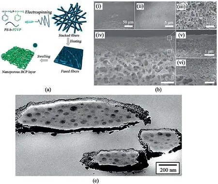
Fig.10.Morphology changes in BCPs.(a).Formation of an ultrafiltration membrane from BCP electrospun nanofibers Reprinted with permission from Shi et al.[90].Copyright(2006)ACS Publication.(b).SEM images of heated BCP fibrous mat prepared with an electrospinning duration of0.5h after ethanol swelling:(i-iii)surface morphology at different scales;(iv)cross-sectional morphology;(v,vi)magnified morphological features of(iv).Reprinted with permission from Shi et al.[90].Copyright(2006)ACS Publication.(c).Cross-sectional TEM of thermally annealed electrospun PS-b-P4VP(PDP)1.0with nominally24wt% of P4VP(PDP)1.0(S24.480k,MW=47990g mol-1),showing more bulk-like morphology.The fiber was coated with a thin chromium layer to allow annealing.Reproduced from Ruotsalainen et al.[91]with permission from RSC Publication.
Contrary to the usage of a printed patterned nozzle,3D scaffold models can be directly printed by a3D printer,followed by the infusion of ESNF into the scaffold[83].The porosity of the structure can be improved by freeze-drying of the scaffold before or after the deposition of the ESNF[84,85].Electrospinning and3D-printing are quite exciting,but there are still limitations such as slow printing rate[86],cost of bioinks[86],and low printing resolution[83].Moving back to self-assembled honeycomb structures,Yao et al.[82]stated that adjusting working distance gives better control of the diameter and area of fibers;thus,pore diameter can be affected.However,it is unclear if this will provide enough improvement to the pore sizes.Thus,freeze-drying will improve the pore features,while deposition time can be increased to improve scaffold thickness and strength.But this process can be very time consuming and inefficient.Chen et al.[77]reported a needleless electrospinning method for fabricating honeycomb structures.This method improves both the spinning time and the scale of the production of honeycomb nanofibers.While this method exhibits high fiber uniformity,the voltage required for electrospinning is very high[77].As indicated in the study,this novel approach has not been carried out in any studies.However,it will be interesting to see if this method can be replicated for other structures.
3.2.4.Block copolymers
Block Copolymers(BCPs),like the honeycomb network,are desired due to their self-assembly nature.Their intrinsic self-assembly nature allows them to exhibit fascinating nanoscale morphologies such as spheres,cylinders,and lamellae with high surface-area-to-volume ratio[4].Electrospun BCPs are rarely studied and are more prevalent in bulk or thin films.Studies on electrospinning of BCPs can be classified into two objectives:(1)controlling the functionality of the fibers and(2)controlling long-range ordered BCPs phase-separated structures inner fibers[87,88].The former,mainly associated with controlling both hydrophilicity and hydrophobicity of the block copolymers,sometimes to improve their biocompatibility.
Common examples of BCPs include PCL and PLA[87].Both BCPs are biocompatible,but their hydrophobicity limits their biomedical use.However,studies have managed to improve the biocompatibility of BCPs mainly by blending with hydrophilic BCPs like PVP.J.Sung et al.[89]electrospun PCL nanofiber scaffold with a biocompatible,amphiphilic poly(N-vinylpyrrolidone)-b-polycaprolactone(PVP-b-PCL)block copolymer to enhance the surface of the PCL/PVP-b-PCL nanofiber scaffolds which will make it more hydrophilic and compatible with the ECM.Other studies have simply introduced various other methods to improve BCPs'functionality.
For example,Shi et al.[90]were able to fabricate ultrafiltration membranes by introducing nanopores into as-spun BCPs fibers through selective swelling in hot ethanol,seen in Fig.10a and b.This method not only turned BCPs from solid to porous fibers but also has the potential of building into a 3D scale,exhibiting spherical micelles.According to Chen et al.[88],3D interconnected nanopores such as polystyrene-b-poly(2-vinylpyridine)(P2VP)are easily controlled and exhibit better water permeabilities than the more commercially available membranes.Weaker BCPs fibers can undergo an annealing process or could be either blended with other polymers or coated with thin metal,as shown in Fig.10c91.In general,the blending of other polymers with BCPs is a typical way of controlling the functionality of BCPs fibers.
Phase separation of BCPs is generally well studied in the bulk and thin-film state compared to electrospun BCP fibers[4].As said earlier,annealing can improve the functionality of BCPs.It can also be used to complete the phase separation of the BCPs fibers by activation of the frozen entities of the polymer's backbones[12].This is often done if there is not enough time for phase separation during electrospinning.
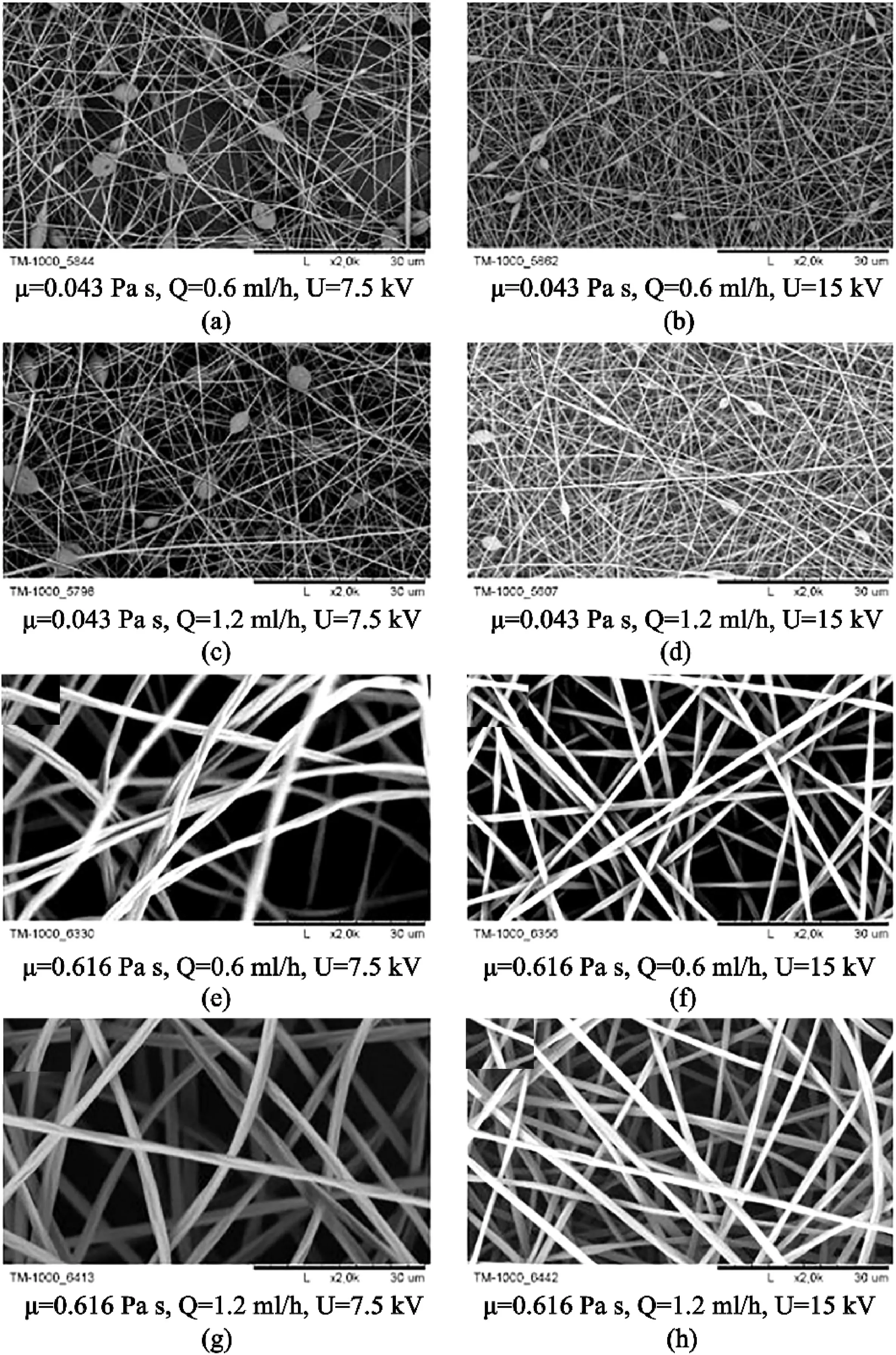
Fig.11.SEM images of nanofibers obtained under various conditions(a)PVP8%(μ-,Q-,U-)(b)PVP 8%(μ-,Q-,U+)(c)PVP8%(μ-,Q+,U-)(d)PVP 8%(μ-,Q+,U+)(e)PVP20%(μ+,Q-,U-)(f)PVP 20%(μ+,Q-,U+)(g)PVP20%(μ+,Q+,U-)(h)PVP20%(μ+,Q+,U+),where“+”indicates the high level of the given factor and“-”indexes the low level of the given factor.Note:“μ”is the viscosity,“Q”is the feed flow,and“U”is the voltage.The black scale bar underneath all images is30μm.Adapted from Korycka et al.[94].
Nonetheless,the most promising approach to producing long-range ordered periodic phases is through the guiding and directing the selfassembly of BCPs,often through chemically or topographically patterned substrates[87].Most phase separation of long-range ordered BCPs are preferred along or perpendicular to the fiber axis[12,87,88].Many studies often prefer coaxial spinning to control the phase separation of BCP fibers.Both Otsuka et al.[92]and Chen et al.[88]reported the confinement of the BCP fibers in a shell.The shells acted to retard and control the rapid solidification and phase separation of the core BCP during electrospinning and the annealing process.Otsuka et al.[92]reported a gyroid-type structure from the BCPs of core poly(-styrene-b-dimethylsiloxane),with a poly(methacrylic acid)shell.Chen et al.[88]later claimed that this phase-ordered structure of BCPs was necessary for shorter diffusion distances for ions and gases in porous structures.
3.2.5.Beads-on-a-string
Beads-on-a-string fibers are one of the most common primary structures.Unlike other primary structures,beaded nanofibers are generally undesired.Yet,they are useful for applications such as drug delivery and fog harvesting due to their ability to encapsulate drugs and exhibit superhydrophobicity[19,93].Beads-on-a-string fibers,as their name suggested,are continuous fibers with beads located along their long fiber axis.The beads,typically a microscale size,occur due to the inability of the polymer chains to overcome Rayleigh instability[22].They have been shown to have different shapes such as spherical or spindle knots,similar to the shape of spider silk[19,22].Factors affecting the formation of beads-on-a-string fibers are well-researched.The background on electrospinning in Chapter2provides details for factors affecting the appearance of beads.These factors can affect beads formation independently.However,there are often too many variables to consider when determining their effect.
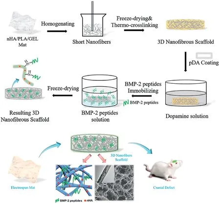
Fig.12.Tissue engineering application:fiber mat composed of nanohydroxyapatite/PLA/gelatin freeze-dried into3D scaffold for resolving cranial defects in rats.Reprinted from Ye et al.[15]with permission from Elsevier.
With the use of factorial design,Korycka et al.[94]compared the most important factors affecting both bead-free and beaded nanofibers.The study found that bead free polymer mainly depended on electrical voltage,while the viscosity and flowrate were less vital(Fig.11).For the beaded fibers,the most critical factor was the viscosity of the polymer feed,and electrical voltage was the second major factor.This is indirectly in agreement with Xue et al.[22]and Ghorani et al.[95],with both studies suggesting that concentration has the most impact because the concentration needs to be above a specific limit to overcome Rayleigh instability.
However,all the solution properties are directly dependent on the polymer's concentration.Despite the importance of polymers in bead formation,the influence of solvents used is often overlooked.Solvents account for about80–90wt% of all polymer feed,thus influence electrospinning morphology,and fiber density is quite high[95].For example,when Li et al.[96]decreased the solvent ratio of chloroform to acetone,the concentration range for the poly(lactic-co-glycolic acid)(PLGA)became smaller.Increasing the PLGA concentration within this range showed a change in bead shape from oval to slender.
Another solvent's influence was seen in the study of Gernhardt et al.[97].In electrospinning of poly(N-isopropylacrylamide)(PNiPAAm)and a copolymer of methyl methacrylate and butyl methacrylate P(MMA-co-BMA)mixture,changing the solvent from a blend of chloroform and DMF to pure DMF led to a structural change from side-by-side structure to a coaxial bead-on-string fiber.A study by Tian et al.[98]also fabricated hydrophilic beads on hydrophobic strings via coaxial electrospinning by using a low viscous outer fluid and spinnable inner fluid.
Primarily-structured nanofibers are usually prepared via simple onestep electrospinning.For example,core-shell nanofibers can be fabricated by using immiscible polymer blends,emulsions,or coaxial or triaxial spinneret setups.Side-by-side electrospinning is another multifluid-feed method to achieve heterogeneous nanofibers,with both hydrophilic and hydrophobic properties in the same nanofiber.Other primarily structured nanofibers,such as,honeycomb structure and block copolymers can be formed by self-assembly without the use of any unique or complex electrospinning setup.In the case of beads-on-a-string fibers,the polymer concentration and the chosen solvent are the critical factors.
4.Application
4.1.Tissue engineering
Tissue Engineering is an exciting aspect of nanotechnology.It aims to alleviate some of the problems of traditional tissue graft,such as availability and morbidity of the donor[15].Through different fabrication techniques such as3D electrospinning and3D printing,scaffolds that mimic the ECM could be fabricated for cell repair and regeneration[16].However,problems still arise from the structural stability and the size of pores encountered in ESNF.Freeze drying is one of the most effective ways of generating macropores required for cell migration and tissue regeneration.
Some of the most common applications of tissue engineering are in bone and cartilage tissue regeneration.Bone has a complex structure and composed of inorganic nanocrystalline hydroxyapatite(HAp)and porous nanocomposite of collagen type I[99].Previous studies,as highlighted by Yu et al.[76],scaffolds fabricated using metals,ceramics,and other non-biodegradable materials can cause adverse effects on the body.However,as ceramics are structurally very similar to bone,Sofi et al.[100]implied that they could be blended with versatile polymers due to their biodegradable and biocompatible features.Such polymer fibers include PLA,PCL,and polyglycolic acid(PGA)[34].Ye et al.[15]built ECM mimicking structure from electrospinning nano-HAp/poly-L-lactide acid(PLLA)/gelatin,followed by the combination of homogenizing,freeze-drying,and thermal crosslinking(Fig.12).The scaffold possesses an interconnected and multilevel porous structure.With the help of polydopamine(pDA)bone morphogenetic protein(BMP-2),peptides(stimulates bone production)are secreted for21days.The combination of BMP-2peptides and nano-HAp helped with bone regeneration in a rat cranial bone defects model.Unlike bones,scaffolds for cartilage and functional tissues like skin and bladder are challenging to fabricate because they are avascular and have limited diffusion pathways[101].
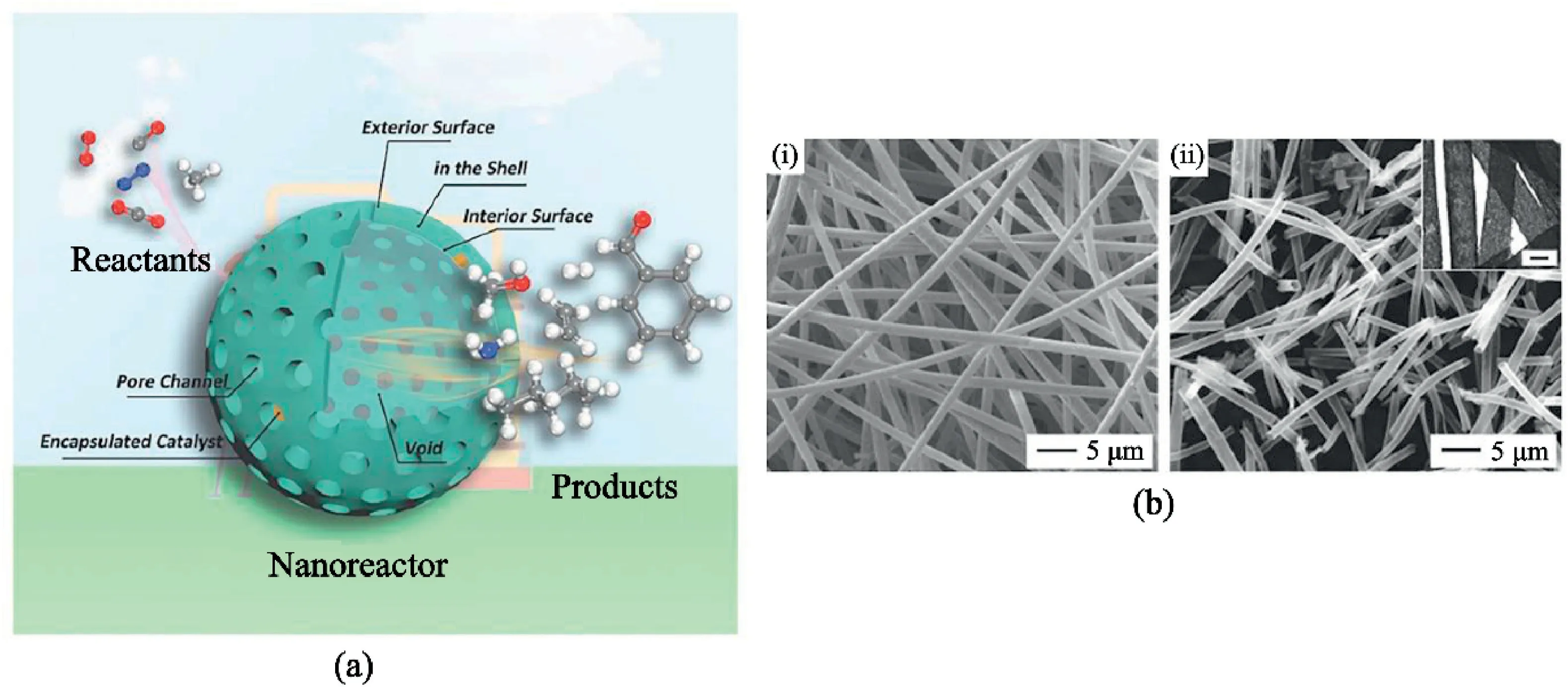
Fig.13.Catalytic application of hierarchical nanofibers.(a)Illustration of hierarchical hollow nanostructure usage as a nanoreactor.Reprinted from Wiley Publication[107].(b)SEM images of PS fiber membrane coated with Pt nanoparticles and CeO2sheaths(i)before and(ii)after calcination in air at400°C for2h;inset shows TEM image confirming hollow structure with scale1μm.Reprinted from Wiley Publication[106].
Mellor et al.[102]combined the use of electrospinning and3D printing to build scaffolds suitable for the growth of the human adipose-derived stem cells(hASC).The study was successful,as the scaffold supported an increasing growth of the hASC over21days.Then the3D-printed-electrospun scaffold was compared to an ordinary electrospun scaffold for a cadaveric pig knee.The electrospun scaffold broke down due to structural limitations,while the3D printed-electrospun scaffold was successful.Diffusion limitation in cartilage can potentially be solved by freeze-drying.Reys et al.[103]developed a3D porous scaffold from chitosan of crabs and shrimps through freeze-drying.Hence,this technique has the capability of improving cell pathways for cartilage regeneration.
4.2.Drug delivery
Drug delivery is one of the most studied applications for the use of ESNF.Through hierarchical structures on ESNF,higher surface area,interconnected pore structure,and biocompatible components feature help to initiate drug delivery.SBS fibers and core-shell fibers are the most used for drug delivery,and they are both fabricated through coaxial electrospinning.
An important area of drug delivery is the kind of delivery mechanism employed,which could be either fast or slow.In SBS fibers,studies have generally allowed one side of the fiber to be capable of a quick delivery,and the other side has a more controlled slower release.For example,Yu et al.[76]fabricated an SBS fiber with one face adsorbing PVP K60 loaded with ketoprofen(KET)(PVP K60/KET),and the other with ethyl cellulose(EC)also loaded with KET(EC/KET).Through biphasic drug release,the PVP K60would dissolve rapidly,hence releasing the KET component.The other side was prevented from rapid release due to the addition of PVP K10for a slow and controlled release.A quick drug release offers many advantages such as immediate alleviation of pain from accident victims,or prevention of virus growth[34]etc.A modified release system could help to maintain drug concentration over a period while reducing the side effects to the user[104].
Core-shell fibers are also often used as a slow-release system to prevent the burst release of drug particles[1].The shell acts as a barrier to prevent accidental loss of active component[68].An example of the core-shell delivery system was carried out by Qian et al.[105].Similarly to Yu et al.[76],EC was used to contain the active ingredient,and with acetaminophen in the shell,a slow controllable release was obtained by this process.Another benefit of core-shell was that the core did not have to be electrospinnable,thus widening applications to different bioactive components.Other fabrication structures capable of drug delivery are hollow fibers and beads-on-a-string fibers.The latter was used in the encapsulation of bovine serum albumin-loaded dextran into PLGA polymer,in which the number of beads was used to control the release of drug particles[93].
4.3.Catalysis
Applications of catalysts can vary from plant operation to automobiles.The best catalyst will have an adequate surface area,low deactivation rate,and excellent conversions.Hierarchical nanomaterials aim to produce an improvement on catalyst already possessing these.This study will report some catalytic applications provided by hierarchical structures in hollow fibers,nanosheets,and nanorods.
Yoon et al.[106]reported the oxidation of CO from hollow CeO2loaded with Pt nanoparticles on its inner surfaces.Before the calcination leading to hollow formation,the fiber had a core-shell with CeO2loaded uniformly on the surface of Pt catalyst as the shell and electrospun polystyrene as the core(shown in Fig.13bi and13bii).This structure allowed the Pt catalyst to improve its CO oxidation by order of magnitude between2and3,with the reaction still stable at a temperature as high as 700°C.This high temperature and conversion rate indicated a sintering-resistance and highly reactive structure.Zhu et al.[107]attributed the success of hollow materials to the controllable synthesis of hollow nanomaterials with excellent support for different reaction types(illustrated in Fig.13a).The study also suggested that hollow nanomaterials possess the high activity of2D nanomaterials and a solid,stable structure of3D architecture.All these attributes allow it to operate similarly to nanomaterials,either as a catalyst or support.
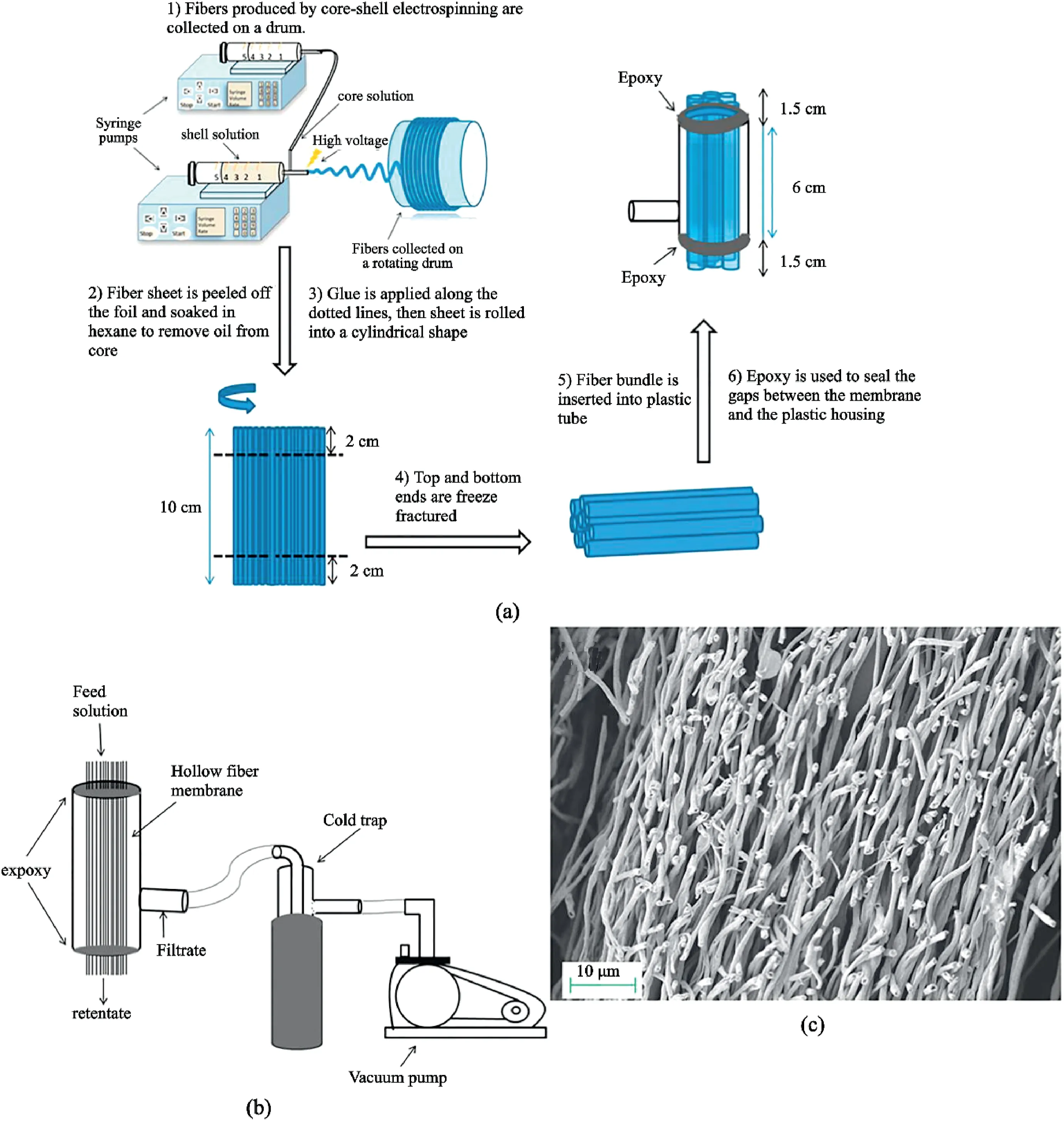
Fig.14.Filtration application:(a)Process of preparing hollow fibers for filtration.(b)Filtration usage of the hierarchical hollow fiber formed in(a).(c)Cross-section morphology of the hollow fibers.Reprinted with permission from Anka and Balkus[111].Copyright(2013)ACS Publication.
Another study by Liu[108]was done on the photocatalytic evolution of hydrogen.MoS2nanosheets grown on electrospun TiO2nanofibers via hydrothermal reaction.The TiO2@MoS2structure provided a high photocatalytic production activity of1.68mmol h-1g-1.According to this study,the production rate was amongst the best photocatalytic performance of MoS2.The MoS2nanosheet grown vertically on the TiO2was attached firmly to the electrospun MoS2,making them very useful for electron transfer in the TiO2@MoS2heterostructure.The hierarchical structure not only produces firm,stable catalyst support,it also provides a large surface area for adsorption.Yousef et al.[109]made use of bimetallic nickel-copper grown on carbon nanofibers as a catalyst to enhance the release of hydrogen from ammonia borane.Bimetallic nickel-copper have catalytic activity more than monometallic,and the achieved nickel-copper nanorods loaded on carbon nanofibers decreased the agglomeration that regularly took place on the nanoparticles.This catalyst was chemically stable and had lower activation energy.According to Filiz[110],Ni–Cu-nanorods grown on carbon nanofibers had lower activation energy compared to a simple electrospun metal oxide.
4.4.Filtration
There are many reasons why nanomaterials are used for filtration.Some of this is due to the high flux capability of the nanopore membrane,which helps in minimizing losses in the process industry.They can also be used for purposes to filter drinking water from microscopic contaminants.Some of the most common nanostructures revolve around coreshell hollow fibers,honeycomb structure and,electrospun block copolymers.
In a performance test carried out by Anka and Balkus[111],a membrane made of hollow fibers of PAN was able to filter Indigo carmine dye and NaCl salt from water(Fig.14b and c).The rejection rate of the salt was97.7%±0.6%,and the dye could not permeate through the PAN membrane(setup illustrated in Fig.14a and b).Other studies have made use of creating pores on hydrophobic ESNF for the rejection of water contaminants.For example,Li et al.[37]fabricated nanoporous electrospun PLLA membrane using N-TIPS.The PLLA nanoporous fiber membranes owned a higher specific surface area than nonporous fiber membranes and exhibited significant improvement in hydrophobicity and water permeability.The hydrophobic PLLA had a water flux of 4836.6L m-2h-1with a40.7% and54.9% increase in methylene blue rejection and oil adsorption,respectively,when compared to a non-porous fiber.A hydrophobic membrane for water filtration can increase the reusability of the membrane since the pores do not become wetted.Hybrid membranes are preferred over conventional absorption towers,partly due to the hydrophobicity and nanoporosity in its membrane,such as poly(ether ether ketone)(PEEK).Honeycomb-like polysulphone/polyurethane(PSU/PU)nanofibers were fabricated by Chen et al.[77].The filtration capability was tested against organic and inorganic airborne contaminants.The thick fibers provided mechanical properties,while the thin fibers were used for air filtration.Shi et al.[90]developed a high flux ultrafiltration membrane from electrospun BCPs.Through selective swelling of the BCP fibers into3D perforated fibers,combined with the modulation of the electrospinning parameters,the filtration performances were found to be as high as6100L m-2h-1bar-1,which was approximately10–35times higher than commercially available membranes with similar rejections.
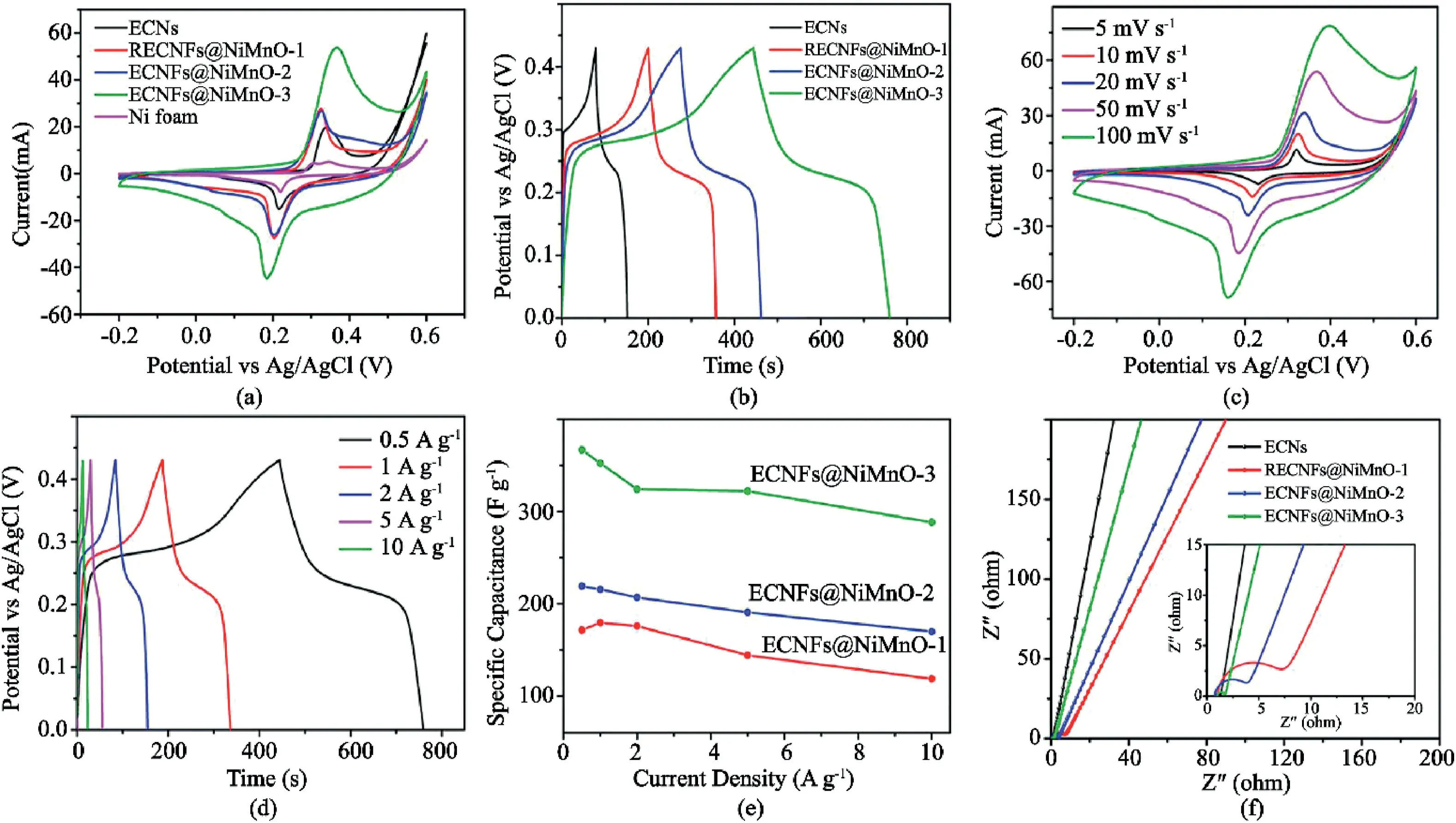
Fig.15.Schematic illustration of improved energy performance of hierarchical nanofibers(a)preparation of the solid-state symmetry cell using NiMn0-3nanosheet on electrospun carbon nanofibers.(b)CV curves for the solid-state symmetry supercapacitor(c)at different scan rates and(d)in different potential windows.GV charge-discharge curves of the solid-state symmetry supercapacitor at various current densities and(e)Ragone plots of energy density and power density at1.4V.(f)Cycling stability of the solid-state device.Reproduced from Tian et al.[3]with permission from RSC Publication.
4.5.Energy devices
Hierarchical structures such as core-shell,hollow fibers,and nanosheets have vast applications in the energy industry.Typical uses of this structure include lithium-ion batteries(LIB)(anode and cathode)[6],supercapacitors[3],and hydrogen storage[6].The desired characteristics for energy storage include high energy density,reduced charging period,adequate safety,and superb cycling life[3].
Zhang et al.[66]reported the creation of anode for LIB using H–Mo2C@C hollow fiber.This structure could withstand charge variations and offer high electron/ion conductivity for Li+insertion and de-insertion processes.Thus,hollow fibers are capable of improving electrochemical properties.Other complex hierarchical structures include3D Fe2O3@NiO core/shell nanorods,as prepared by Xiong et al.[112].Unlike other processes,this core/shell nanorods structure was prepared via hydrothermal synthesis,followed by a series of chemical bath deposition.With Fe2O3nanorods as the core and an interconnected NiO nanosheet as the shell,the anode material for LIB displayed a high discharge capacity of1047.2mAh g-1after50cycles at200mA g-1and 783.3mAh g-1at a high current density of2000mA g-1.This technique provides an alternative to electrospinning in combining hierarchical structures for improved functionality.Radacsi et al.[113]also reported the performance of solid acid fuel cells using electrodes fabricated from ESNF of PVP or PVA and a small amount of emeraldine base polyaniline(PANI),which was decorated with cesium dihydrogen phosphate(CDP)electrolyte nanoparticles.This structure,compared with a standard state-of-the-art electrode,showed increased cell voltage.
Similarly to Xiong et al.[112]and Zhang et al.[66],the electrochemical improvement can be attributed to a high surface area.The presence of a triple-phase boundary arising between the CDP electrolyte,the platinum catalyst deposited via chemical vapor deposition onto the CDP,and the gas-phase(air)also helps to provide extra surface area for electrocatalysis.Therefore,hierarchical ESNF decorated with nanoparticles can even offer more benefits for energy application.
There have also been instances of hierarchical structures for capacitors.For example,Xu et al.[7]grew MnO2nanosheets on NiCo2O4nanotubes.NiCo2O4nanotubes can be used as a template for loading with additional electroactive materials to improve the performance due to its electrochemical activity and high electronic conductivity.Therefore,NiCo2O4@MnO2heterogeneous materials were synthesized to enhance the conductivity of MnO2materials and improve strong synergistic effects between the two materials.As an electrode for supercapacitors,the structures possess a specific capacitance of706.7F g-1at3A g-1,at a high rate capability of approximately84.9% retention of the initial capacitance and excellent cycling stability,which was about136.3%capacitance retention after10,000cycles.Also,nanosheets grown on electrospun carbon ECNF is suggested to be a cheap and efficient option for electrodes for next-generation energy-storage devices.Both Li et al.[54]and Tian et al.[3]grew Bi2O3and Ni–Mn–O on ECNF,respectively.As expected,the nanosheet on ECNF displayed high power density,superb cycling stability,and other impressive characteristics reported in Fig.15.
Hierarchically electrospun nanofibers also have been widely used in a large number of industrial applications.For example,for composite laminate materials against delamination,it can be served as interleaved reinforcement.The complex nanofibrous composite structure has the unique morphology to be embedded between two laminate plies to improve the mechanical performances[114].An et al.[115]fabricatedmultifunctional fiber-reinforced polymer composites through electrospinning thermoplastic nanofibers by polyamide6.6.The composite materials overcame the enormous challenges in inter-laminar toughening.Nezhad et al.[116]combined a conductive electrode layer and layers of piezoelectric thermoplastic nanofibers to prepared fiber-reinforced composite laminates.The fabricated composite materials have been used in situ deformation measurement in some industrial applications,such as high-performance aerospace and renewable energy composites.
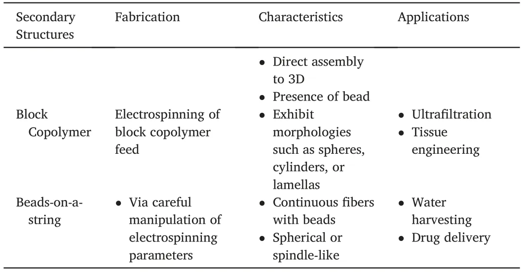
Table3(continued)
5.Summary
Hierarchical ESNF that have been categorized in this review into primary and secondary structure have distinct structures but similar applicability.Their widely differing structures are a result of their fabrication techniques.As this review only primarily focuses on ESNF,all the fibers have undergone electrospinning during their processing.Secondary structures all require ESNF templates,followed by various heat treatment.On the other hand,primary structures are produced by adjusting the electrospinning setup or choosing a specific feed solution.The fiber produced can also rely heavily on modifying electrospinning parameters.Table3summarizes the fabrication techniques,characteristics,and possible applications,as discussed already in this review.
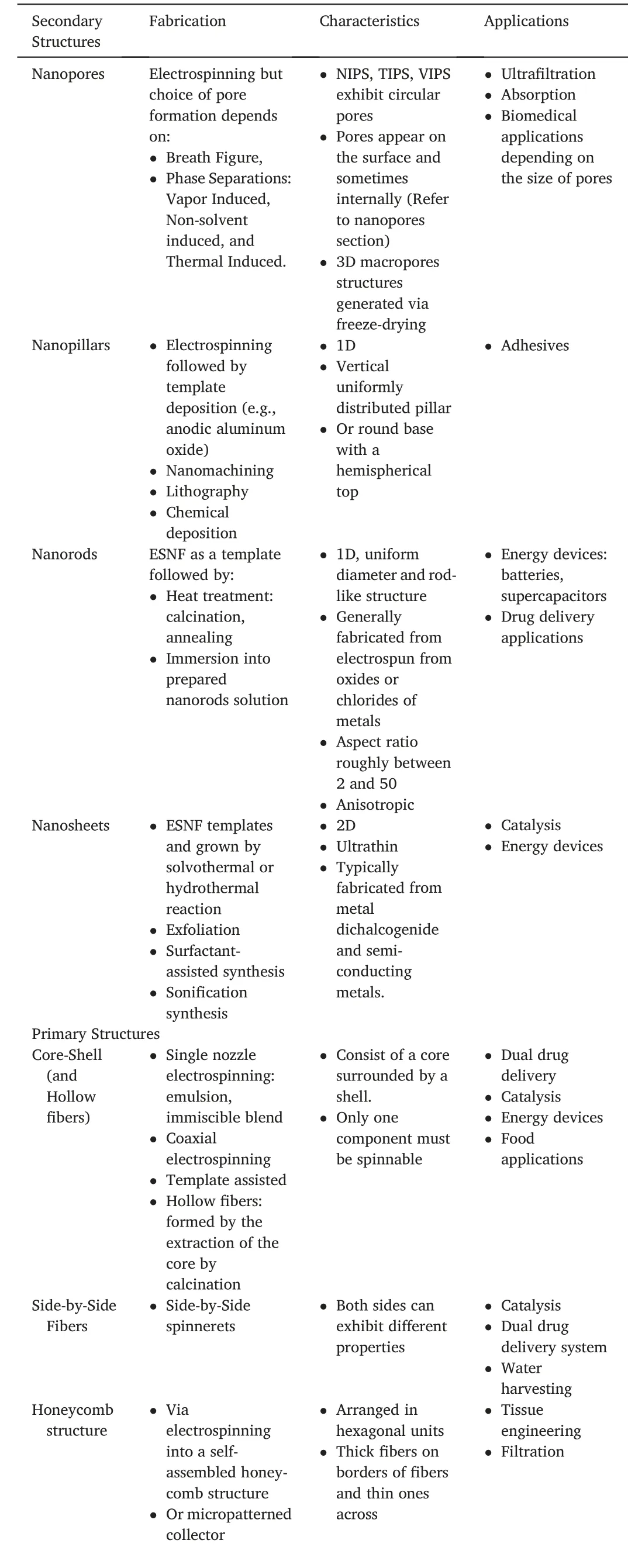
Table3 Summary of fabrication techniques,characteristics,and applications of the secondary and primary structures.The characteristics and applications are not limited to the content in this table.
6.Limitations and outlook
Despite many of the advantages offered by the hierarchical structure,there are some limitations we need to consider.In most of the studies done on nanofibers,electrospinning provides the highest surface area,best pore connectivity,and is also the cheapest and most straightforward method of fabrication.A significant development towards electrospun materials is the building of hierarchical structures,which tries to impart more properties to ESNF.The main problem with hierarchical ESNF is the limited methods of fabrication of these structures,as researchers rarely deviate from conventional techniques for producing hierarchical materials.For example,the controlled production of nanosheets and nanorods on the nanofiber surface is often produced by heat treatment(hydrothermal or solvothermal reactions).Only a few studies have discussed approaches to modify these processes.In nanosheets formation,there are other fabrication techniques such as exfoliation,surfactant-assisted synthesis,etc.,both of which are rarely discussed for hierarchical nanosheet fibers.Studies can be formulated to understand the use of these approaches for electrospun and explore any benefits if one exists.An exception to this argument is the core-shell fabrication,where there are four methods,all requiring some forms of electrospinning.For example,emulsion electrospinning makes it convenient to use food-friendly solvents,while coaxial allows flexibility in deciding the solvents and electrospinning ability of one of the solutions.These advantages have made them prevalent in hierarchical structures study.The problem,however,is not to do with the availability of reviews on them but the limited attention paid to other structures.Electrospun BCPs are rarely studied,but they can offer similar advantages to core-shell fibers in biomedical applications.The presence of two or more monomer units to form BCPs means hydrophilic and hydrophobic properties can be imparted on the same fibers.With further exploration in the less popular structures,more variety of applications can be discovered.
Most often,studies tend to focus more on the functional applications of fibers rather than the formation of this structure.As a result,there is little insight into hierarchical structure formations.Consequently,correlations between different electrospinning parameters are poorly understood.Although,each effect from individual parameters is generally well understood.A correlation for linking most parameters will provide better help for the controllability of nanofiber structures and can even help in developing other fabrication techniques to mitigates some parameter's limitations.A successful approach is the near-field electrospinning technique,a modification of electrospinning,which eliminates bead formation and gives control of fiber morphology with high resolution.
Another limitation of fibers is its uniformity.Currently,fiber uniformity affects the functionalities of different materials.Fiber uniformity is not just associated with the diameter but other morphologies like pores sizes,and beads diameter.Better fiber uniformity can allow for better prediction of fiber characteristics.Arrangement into bulk for mechanical properties can also be a lot easier as well.An example is the use of nanopores for ultrafiltration.Large pore distribution can effectively render pore formation useless.Fortunately,inner pores distribution has not been reported to be a problem in most studies.However,fiber diameters distribution is often a problem in the electrospinning process.
Despite the successful number of applications reported for hierarchical nanostructures,large scale production is still a problem.The alleviation of the problem with the availability of donors through tissue engineering is a huge possibility.Despite this,there needs to be an efficient method in the development of these scaffolds at a much faster rate.Some studies are ahead of the curve in reporting large-scale production through needleless electrospinning.This is a downgrade of electrospinning due to poor control of fiber morphology.But researches can be developed through the electrospinning processes and scaling up approaches using needless electrospinning.
Studies of3D fibers are promising.But currently,some of these structures do not exhibit higher hierarchical structures.Two well-known methods for fabricating both hierarchical structures and3D blocks include freeze-drying and3D honeycomb formation.Although the freeze-drying process produces macropores instead of nanopores,it is still a significant improvement for fiber characteristics,especially for fibers which have pores that are too small for cell migration.The limited number of methods for the fabrication of a hierarchical3D fibrous block presents a problem for3D fibrous scaffolds when it comes to improving structural properties.For example,self-assembled honeycomb can have structural limitations like other direct3D electrospinning processes,such as multilayering.However,3D printing combined with electrospinning can be used to mitigate this issue,but continuous fibers often need to be cut to disperse into the3D-printed scaffold.Besides,3D printing can be expensive or slow.Studies on combining1D nanorods with2D nanosheets could be done to realize the potentials of having both3D and hierarchical morphology.
The study of hierarchical materials is thriving,especially when considering the number of possible applications.However,most of the reviews of the application are related to laboratory research with minimal field trials.Clinical studies will be helpful in garnering more interest and understanding of this field.Research collaboration between the different science and engineering areas can help unlock the potentials in hierarchical nanofibers.Combining different morphologies such as nanorods-on-nanosheets fibers,wire-in-tube fibers,tube-in-tube fibers can potentially widen applications of nanomaterials.
7.Conclusion
In recent years,there has been a shift of studies done on traditional electrospinning to hierarchical electrospun materials.Hierarchical ESNF can be fabricated through simple or modified electrospinning setup,a specific feed solution,or post-processing of ESNF to display fascinating morphologies such as high surface area,better pore connectivity,and improved mechanical stability.These morphologies enhance the functionalities of ESNF.For example,enhanced pore connectivity can improve cell migration within the ECM for tissue regeneration.High surface areas in nanosheets or hollow materials can promote ions exchange or adsorption for battery and catalytic applications,respectively.One of the greatest achievements of hierarchical structures is the ability to impart multiple functionalities in structures,like side-by-side fibers or core-shell fibers.This allows materials to possess both hydrophobic and hydrophilic properties or different drug release profiles.Also,some3D fabrication techniques can directly lead to the fabrication of hierarchical fibers.Self-assembled honeycomb structures and freeze-drying are two effective ways of producing hierarchical3D fibers.The former requires no particular electrospinning setup for assembly into3D honeycomb scaffold,while freeze-drying can introduce pores to electrospun materials.In engineering applications,such as high-performance aerospace and renewable energy composites,toughening layered or laminated fiber-reinforced composites fabricated by hierarchical electrospun nanofibers can be used to sustain deformation mechanisms and hinder damage mechanisms.However,much research still needs to be done for the direct fabrication of both3D and hierarchical morphology.Despite the number of possible applications with hierarchical structures,more researches are required for understanding the correlation between parameters affecting the morphology of the ESNF.And with more interest in the field,especially from the commercialization of some of the products,more hierarchical structures can be researched.
Declaration of competing interest
The authors declare no conflict of interest.
杂志排行
Namo Materials Science的其它文章
- Low-cost fabrication of highly dispersed atomically-thin MoS2nanosheets with abundant active Mo-terminated edges
- RTV silicone rubber composites reinforced with carbon nanotubes,titanium-di-oxide and their hybrid:Mechanical and piezoelectric actuation performance
- Advanced carbon materials with different spatial dimensions for supercapacitors
- Surface microstructure-controlled ZrO2for highly sensitive room-temperature NO2sensors
- Applications of carbon nanomaterials in perovskite solar cells for solar energy conversion
- Synthesis of hexagonal boron nitrides by chemical vapor deposition and their use as single photon emitters
