Enhanced Intrusion Detection System for an EH IoT Architecture Using a Cooperative UAV Relay and Friendly UAV Jammer
2021-10-23VanNhanVoHungTranandChakchaiSoIn
Van Nhan Vo,Hung Tran,and Chakchai So-In,
Abstract—In this paper,the detection capabilities and system performance of an energy harvesting (EH)Internet of Things(IoT)architecture in the presence of an unmanned aerial vehicle(UAV)eavesdropper (UE)are investigated.The communication protocol is divided into two phases.In the first phase,a UAV relay (UR)cooperates with a friendly UAV jammer (UJ)to detect the UE,and the UR and UJ harvest energy from a power beacon(PB).In the second phase,a ground base station (GBS)sends a confidential signal to the UR using non-orthogonal multiple access(NOMA);the UR then uses its harvested energy to forward this confidential signal to IoT destinations (IDs)using the decode-andforward (DF)technique.Simultaneously,the UJ uses its harvested energy to emit an artificial signal to combat the detected UE.A closed-form expression for the probability of detecting the UE(the detection probability,DP)is derived to analyze the detection performance.Furthermore,the intercept probability (IP)and throughput of the considered IoT architecture are determined.Accordingly,we identify the optimal altitudes for the UR and UJ to enhance the system and secrecy performance.Monte Carlo simulations are employed to verify our approach.
I.INTRODUCTION
CURRENTLY,the Internet of Things (IoT)is emerging as a powerful technological paradigm in which a massive number of devices are interconnected with the aim of collecting and transmitting data for different purposes in various application scenarios (e.g.,smart cities,smart factories,and smart agriculture)[1]–[3].In parallel with the IoT revolution,unmanned aerial vehicles (UAVs)are considered promising solutions for numerous applications,such as aerial monitoring,photography,precision agriculture,traffic control,telecommunications,and especially search and rescue [4].Low-altitude UAVs,in particular,have attracted a massive amount of research attention in the context of safe and secure communications due to their mobility,elevated positions,and relatively low cost,which make them an easy and inexpensive way to access a variety of areas for surveillance [5],[6].
Accordingly,UAVs can contribute to overcoming the limitations of the terrestrial infrastructure of an IoT system.Specifically,the incorporation of UAVs into an IoT system can allow such a system to bypass obstacles that may block direct communication between a transmitter and a receiver(e.g.,forests,mountains,or high buildings)[7]–[9].For example,Motlaghet al.discussed the potential uses of UAVs in IoT architectures for applications such as service delivery,pollution mitigation,farming,and rescue operations due to their high mobility [7].Mozaffariet al.presented a comprehensive survey of the uses of UAV communications.The authors indicated that UAVs can serve as wireless relays to improve the connectivity and coverage of ground wireless devices and,in particular,can be utilized in surveillance scenarios,which represent a key use case for IoT technology[8].
Nevertheless,although UAVs can boost the throughput and reach of a communication network,this approach has two limitations.First,a UAV has a finite energy storage capacity,which imposes resource limitations.A UAV needs to intermittently dissociate from the system for battery charging or replacement,which may be very expensive and difficult[10].Thus,to prolong the lifetime of UAVs,energy harvesting (EH)has become a promising approach for supplying energy for information transmission [11]–[13].For example,Jiet al.proposed a system model with EH at two UAV relays (URs),in which the URs transmitted signals via power splitting using the energy obtained via EH [11].Yinet al.focused on a cellular network with an energy-constrained UR and concluded that EH for the UR could improve the uplink rates achieved via cooperative communication from the UR to users [12].
Second,if a UAV acts as an attacker (e.g.,a UAV eavesdropper (UE)),then the network boundary will be breached,and data resources will be compromised [6],[13].For example,Sunet al.reported that a UAV can be exploited to steal confidential data and even perform jamming to reduce the quality of legitimate links,potentially presenting greater challenges than conventional terrestrial eavesdroppers [13].In particular,the work reported in [14] studied the secrecy performance of terrestrial wireless communications in the presence of a UE.The authors investigated the achievable ergodic and average outage secrecy rates for a transmitterreceiver pair on the ground in the presence of an aerial eavesdropper flying along a random spatial trajectory using a smooth turn (ST)mobility model.Furthermore,Tanget al.investigated the secrecy performance of a ground link in the presence of a UE by deriving the secure connection probability [6].Here,the authors assumed that the position and channel state information (CSI)were well known.However,this assumption is strong because an adversarial UE will attempt to hide to facilitate its attacks against a legitimate system.
Therefore,such a system needs a means of detecting and reacting to ongoing attacks,which is referred to as an active intrusion detection system (A-IDS)[15].The operation of an A-IDS is divided into two steps:first,UE intrusion detection is performed,and then,once an intrusion is detected,a mitigation approach (e.g.,a friendly UAV jammer (UJ))is deployed to minimize the undesirable effects of the ongoing attack.For UAV detection,Nguyenet al.proposed a technique for localizing a UAV and its controller by means of a cost-effective passive tracking system.Based on the radio frequency (RF)signals emitted by a UAV and its controller,a new solution for identifying their angles and locations was presented [16].In that work,techniques for detecting the appearance of a UAV were proposed.However,the question of how to combine such a detection technique with a means of ensuring secure communications in the presence of the detected eavesdroppers was not investigated.
For combating eavesdropping attacks,there is great interest in the ability to transmit an adversarial signal against a UE using a UJ [6],[17].For example,Wanget al.claimed that a UJ offers a means to cooperatively improve security by transmitting artificial noise [17].More specifically,the authors of [18] considered a UAV equipped with an air-toground friendly jammer to support secure communications between a valid transmitter-receiver pair for unknown eavesdropper locations.To ensure the system’s reliability and stability,the effects of the UAV’s jamming power and its three-dimensional (3D)spatial deployment on the outage probability (OP)of the legitimate receiver and the intercept probability (IP)of the eavesdropper were analyzed.In addition,Tanget al.investigated the secrecy performance of a legitimate ground link being monitored by UEs within a finite spatial area.A UJ was employed to improve the security of the ground communication.The authors concluded that a maximum increase of 75% in the secure connection probability could be achieved using a UJ [6].
Based on the above survey of the literature,it can be anticipated that cooperation between a UR and a UJ can significantly improve the system and secrecy performance of an IoT system.However,to the best of our knowledge,no existing work has investigated an A-IDS that relies on such cooperation to identify and interfere with a UE in 3D space.The primary contributions of this paper are summarized as follows:
1)We propose a secure communication protocol with two phases:a detection phase and a communication phase.For the detection phase,we propose a system of two cooperating UAVs,a UR and a UJ,for identifying a UE in 3D space;this system is a form of A-IDS.In the communication phase,a ground base station (GBS)transmits a confidential signal to the IoT destinations (IDs)with the assistance of an EH UR to improve the system performance;furthermore,an EH UJ is utilized to enhance the secrecy performance once a UE has been detected.
2)We derive a closed-form expression for the detection probability (DP)to analyze the performance of UE detection.Furthermore,closed-form expressions for the throughput and IP are obtained to evaluate the system and secrecy performance.
3)We investigate the trade-off between throughput and secrecy performance.Then,an algorithm is proposed for determining the optimal altitudes of the UR and UJ to improve the system and secrecy performance.
II.RELATED WORk
In this section,recent works on UAV detection and UJs are briefly surveyed.
Because of the danger posed by unknown UAVs,there is a need to investigate related methods of robust detection,tracking,and interruption [16],[19].For example,Ezumaet al.investigated the problem of detecting and classifying UAVs in the presence of wireless interference signals using RF fingerprints.The investigated system included a passive RF surveillance mechanism based on listening to the signals transmitted between a UAV and its controller.The classification performance was evaluated in terms of the classification accuracy [19].
However,the localization of a detected UAV for the purpose of estimating the distance between the legitimate system and the UAV was not considered.To address this shortcoming,Nguyenet al.proposed a system consisting of two stations for determining the locations of an unknown UAV and its controller.The authors analyzed an RF-based signal to determine whether a peak in the incoming RF signal strength in a given direction corresponded to a drone or its controller and utilized triangulation to estimate their locations[16].However,evaluation of the DP was not considered.Furthermore,the two stations were both located on the ground,making detection difficult for an unknown UAV flying at a high altitude.
To improve the secrecy performance of a communication system,a UJ emitting a jamming signal against an attacker can be employed as a potential solution [6],[17],[18],[20].For example,Wanget al.presented an overview of recent research efforts on secure communications involving a UAV in the physical layer.The authors focused on the architectures of the reviewed secure transmission schemes in regard to the different roles of UAVs,including the possibility of using a UJ to enhance the secrecy performance by exploiting the characteristics of UAVs [17].
More specifically,Zhouet al.investigated a system that includes a legitimate transmitter and receiver that are being monitored by an eavesdropper at an unknown location.Furthermore,a UAV equipped with an air-to-ground friendly jammer was employed to assist in secure communication.The authors examined the effects of the power of the UJ and its 3D spatial deployment on the system performance in terms of the OP of the legitimate receiver to evaluate the enhancement in reliability.In addition,the secrecy performance in terms of the IP of the eavesdropper was assessed to evaluate the system security [18].
Liet al.considered physical-layer security for UAV-ground communications.The system model consisted of a UAV serving as the GBS to transmit confidential signals to a legitimate ground user,along with multiple unknown eavesdroppers on the ground.To improve the secrecy performance of the considered system,a UJ can be employed to transmit jamming signals to confuse the eavesdroppers.The authors concluded that the secrecy performance of the proposed system with a UJ can be significantly improved compared to that of the system without a UJ [20].However,in these two papers,the eavesdroppers remained on the ground,making them easier to detect than UEs.
To extend the scope of possible eavesdroppers,Tanget al.investigated the secrecy performance of a ground link with random deployment of noncolluding UEs,with a UJ placed near the UEs to send a jamming signal.The secure connection probability was investigated to analyze the secrecy performance.Furthermore,the impacts of the jamming power and location of the UJ were considered.The optimal combination of jamming position and power to achieve the optimal secrecy performance was derived [6].However,the researchers assumed a scenario with perfect CSI for the UEs.This assumption is strong because of the unknown locations of the UEs.
No previous publication has investigated the trade-off between the DP for a UE and the throughput with imperfect CSI to achieve a certain security constraint for an EH IoT system.Thus,in this paper,we focus on this issue and examine the system and security performance of such an IoT system.
III.SYSTEM MODEL AND COMMUNICATION PROTOCOL
In this section,we introduce the system model,channel assumptions,communication protocol,and scheduling schemes.
A.System Model
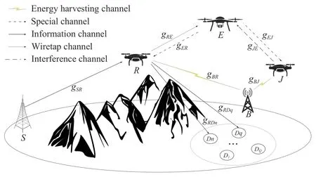
Fig.1.An illustration of an IoT architecture with a GBS S,a power beacon(PB)B,an UJ J,a UR R,and multiple IDs D being monitored by a UE E.
We consider the multiple-input single-output (MISO)IoT architecture shown in Fig.1 [21].Here,we assume that the considered model is applied in a mountain or forest area where the prevalence of Wi-Fi and Bluetooth signals is low.This is a practical assumption for scenarios at borders where surveillance activities are often conducted.In particular,we address a practical scenario [4],[13] in which a GBS needs to send information to multiple IDs.Due to the presence of obstacles (e.g.,mountains,forests,or buildings)and the distances involved,a UR is utilized to help the GBS forward the information to the IDs using non-orthogonal multiple access(NOMA).The IDs are randomly divided into multiple orthogonal pairs,and NOMA is implemented between each pair[22],[23].Without loss of generality,it is assumed that theqth ID (Dq)andn-th ID (Dn)are paired to perform NOMA transmission,whereDqis located farther from the UR thanDnis,i.e.,.
Furthermore,an unknown UAV (referred to as a UE)that attempts to join the legitimate system with the intent of stealing information is also considered [13].To identify the UE,a UAV (referred to as a UJ)is deployed.This UAV serves two purposes:first,cooperating with the UR to serve as a form of A-IDS for identifying the UE,and second,combating this enemy by emitting artificial noise signals to improve the security of the confidential signals.In addition,due to the limited energy resources of the UR and UJ,a PB is employed that transmits a dedicated RF signal to provide the energy needed for the legitimate UAVs to communicate with multiple IDs [24].
Note that the IDs are each equipped with a single antenna due to their size and capability limitations,while each component of the A-IDS (i.e.,the UR and UJ)has multiple omnidirectional antennas for detecting the presence of UE signals and a mechanically agile antenna for identifying the direction of the UE [16].Furthermore,the UE is also equipped with multiple antennas to easily steal confidential signals [13],while the PB has multiple antennas to enhance the EH performance at the legitimate UAVs [25].The main notations employed to describe the system model are listed in Table I.
B.Channel Assumptions
In this subsection,two types of channels for UAV communications are introduced:a ground-to-air or air-toground channel and an air-to-air channel.Without loss of generality,all channels are assumed to be mutually independent [6],[20] and are described using the notation defined in Table I.

TABLE I NOTATIONS
1)Air-to-Air Channel:Adopting the method of [26],the path loss of an air-to-air channel in units of dB is formulated as

wherea∈{RE,JE},da∈{dRE,dJE},and ηaand ϕaare the path-loss exponent and the path loss at a chosen reference point,respectively,of the air-to-air link.Furthermore,because there are no obstacles in the sky,the air-to-air channel is described by the Friis free-space transmission formula [6],i.e.,ηa=2 and ϕa=10log10(4πf/c)2,wherec=3×108m/s andfis the carrier frequency.Thus,the model for the absolute value of the air-to-air path loss is expressed as

2)Ground-to-Air Channel:Similarly,the path loss of a ground-to-air channel in units of dB is given as

whereb∈{S R,S J,BR,RD},db∈{dSR,dSJ,dBR,dRD},and ηband ϕbare the path-loss exponent and the path loss at a chosen reference point,respectively,of the ground-to-air link.Furthermore,the model for the absolute value of the groundto-air path loss is expressed as

where µb=.According to [9],[20],a ground-to-air channel is more likely to be dominated by either line-of-sight(LoS)or non-line-of-sight (NLoS)conditions depending on the environment (e.g.,rural,urban,or dense urban).Thus,ηb=2,and the quantity µbis formulated as [26]

whereθis the UAV elevation angle with respect to either the GBS or ID,i.e.,θ ∈{θBR,θRDq,θRDn};φandψare constants that depend on the environment (rural,urban,or dense urban)[27];and ωLoSand ωNLoSare environment-and frequencydependent parameters that represent the excess path losses of LoS and NLoS links,respectively,as a result of shadow fading [27].This model can be applied to the channels between the GBS and the UR,between the UR and the IDs,between the PB and the UR,and between the PB and the UJ.
Furthermore,due to the unknown nature of the UE,imperfect CSI is considered for the UE-UR and UE-UJ links,i.e.,,and,andare the channel coefficients estimated by using the MMSEs forgER,gRE,gEJ,andgJE,respectively,andeER,eRE,eEJ,eJE∼CN(0,Ωe),withΩebeing the correctness of the channel estimation and CN(0,Ωe)being a scalar complex Gaussian distribution with zero mean and variance Ωe[28]–[31].In addition,we assume that the ground-to-air,air-to-ground,and air-to-air channel gains are modeled as the gains of Nakagami-mfading channels with a fading severity parametermXY[2],i.e.,the channel gains are random variables (RVs)distributed following a gamma distribution.Thus,the PDF and CDF of the channel gaingXYare formulated as [32]

wheregXYis an RV with a mean value ofand Γ(·)is the gamma function.
C.Communication Protocol
We propose a communication protocol that consists of two phases,as follows:
1)In practice,the UE will need to exchange some messages,either with its controller or with other outside devices.This means that the UE in this case is a semipassive device that occasionally sends a signal to its controller,and thus,it can be detected.It should be noted that the case in which other interferences exist is not considered in the scope of this paper,and our system model is applicable to scenarios such as mountain or forest areas,with a low prevalence of Wi-Fi and Bluetooth signals [33].Therefore,in the first phase αT,i.e.,the detection and EH phase,each legitimate device switches its listening status to“on”at a selected omnidirectional antenna with the purpose of detecting a signal from a UE.Thus,the UR and UJ attempt to identify whether a UE signal is present [33].We consider the case in which a UE is detected,which means that the UR and UJ each receive the signal from the UE as follows:


where θRand θJare obtained as previously described and.By solving these equations,the UR-to-UE and UJ-to-UE distances are obtained.Furthermore,the signal-to-noise ratios (SNRs)for decoding the unique signal from the UE at the UR and UJ are formulated as follows [18]:

Notably,we consider the case in which the energy resources of the legitimate UAVs are limited [12],[34].Thus,to prolong their lifetimes,the UR and UJ must harvest energy from the PB via wireless power transfer (WPT),i.e.,the amounts of energy harvested by the UR and UJ in the first phase αTcan be formulated as [24],[35]
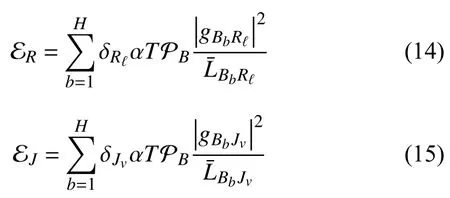
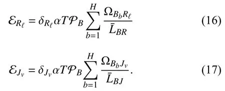
Note that from the UE activity model,if αTand βTdenote the detection time for the first phase and the communication time for the second phase,respectively,within the frame durationT(as shown in Fig.3),then the a posteriori probabilities can be expressed as [39]
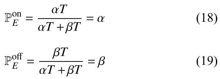

Fig.2.Localizing the UE.

Fig.3.The proposed communication protocol with time splitting in EH for detection,EH,and information processing.
2)In the second phase βT,i.e.,the communication phase,the cooperative communication process is divided into two subphases that occupy equal parts of the remaining time duration,i.e.,with lengths of βT/2 [40].
i)In the first subphase,the GBS transmits a superimposed mixed signalxS=to the UR using transmit antenna selection (TAS)[21],wherexqandxnare the signals to be received byDq(far ID)andDn(near ID),respectively,and ϱqand ϱnare power allocation coefficients that satisfy the conditions ϱq+ϱn=1 and ϱq>ϱn[23].Therefore,the signal received at theℓ-th antenna of the UR in the first subphase is expressed as [37],[41]


Next,Rℓsubtracts the message for the far ID to obtain that for the near ID.Here,it is assumed that by adopting the successive interference cancellation (SIC)method proposed in[29],[42],Rℓcan successfully decodexq.Thus,the SINR atRℓfor detectingxnfrom the GBS can be formulated as

ii)In the second subphase,to improve the throughput,the UR applies the decode-and-forward (DF)technique to decode the superimposed signal [21] and chooses 1 antenna for forwarding this signal to the IDs using the energy harvested in the first subphase,PR=ER/βT/2 [21].Furthermore,due to the broadcast nature of the signal,the UE can steal the superimposed signal from the UR.Thus,the UJ is utilized to combat the UE (identified in the detection phase)by emitting a jamming signalxJ.Here,the legitimate devices initially synchronize with each other by generating and indexing the same set of Gaussian pseudorandom jamming signals [43].Thus,the IDs can disregard the interference signal,while the UE receives both the confidential signal and the jamming signal.Accordingly,the received signals at theσ-th ID and the UE can be expressed as
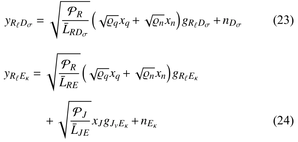

Similarly,the UE uses the NOMA technique to detectxqandxn.Therefore,the received SINRs atEκfor decodingxqandxnare expressed as
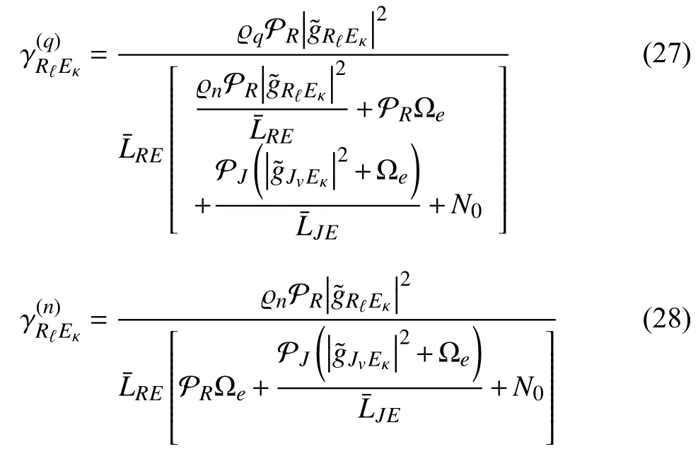
where PJ=EJ/βT/2.
IV.OpTIMAL ALTITUDE OF THE UJ FOR DETECTING A UE
In this section,the probability of UE detection is analyzed.This metric is defined as the probability that the UR or UJ successfully decodes the unique signal from the UE in the first phase.Specifically,by combining the a posteriori probabilities of detection with the maximal capacity received atRℓandJv,which should be greater than the target rate,the DP can be expressed as follows:

where Pr{·} is a probability function,δDis the target rate,and the channel capacities fromEκtoand fromEκtoJvare defined as

whereWis the bandwidth.It should be noted that the UR and UJ each need to choose the best antenna for receiving the UE’s signal to enhance the DP,i.e.,

Lemma 1:The DP for the UE is expressed as follows:

where ∆ERand ∆EJare defined as follows:

The proof is given in Appendix A.
V.SYSTEM PERFORMANCE ANALYSIS
A.Throughput
Communication transmission may be interrupted if the endto-end SINR that is achieved for an ID is below a certain outage threshold.Therefore,the OP of an ID can be defined in terms of an outage threshold,,as follows:

where the channel capacities fromSmtoRℓand fromRℓtoDσare defined as

Here,the antennas of the GBS and UR that are selected in the first subphase are chosen to improve the system performance based on the best GBS-to-UR channel gain,as follows:

Moreover,to ensure that all IDs can receive their confidential messages,the antenna of the UR that is selected in the second subphase is chosen to maximize the channel gain from the UR to the farthest user,i.e.,

Lemma 2:The OP of theq-th andn-th ID is expressed as


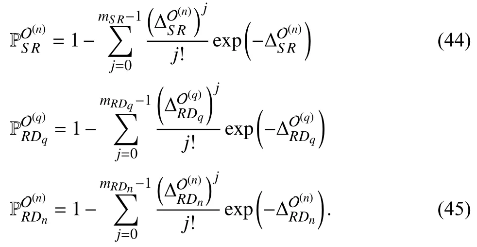
The proof is given in Appendix B.
Based on lemma 2,the throughput of theσ-th ID is formulated as follows [44]:

B.IPs for xq and xn
To analyze the leakage of confidential packets,the IP is investigated.This metric is the probability that the channel capacity at the UE is larger than a certain positive threshold,,and can be expressed as [18]


Furthermore,to improve the IP,the UE chooses the best antenna to steal the UR’s signal,i.e.,

Lemma 3:The IP at the UE for stealing the message intended for the σ-th ID is expressed as

The proof is given in Appendix C.
C.Strategy for Enhancing the Security and System Performance of an IoT System in the Presence of a UE
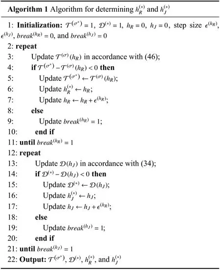
Remark 1:The models of the path losses from the GBS to the UR and from the UR to the IDs are functions of the altitudehRin the form of the angles of elevation θBR,θRDq,and θRDn,as shown in (5).IncreasinghRwill make the corresponding ground-to-air and air-to-ground links closer to LoS links but will also increase the path losses.Thus,there may exist an optimal altitude of the UR to achieve the best throughput [26].Furthermore,the DP for a UE is small when the altitude of the UJ is low due to the long distance from the UJ to the UE.Thus,the value of the function D in (34)will be increased if the UJ flies higher.However,if the altitude of the UJ is too high,the function D will begin to decrease again,i.e.,there exists an optimal altitude for the UJ such that the DP for the UE reaches a maximum value.Therefore,to enhance the security and system performance,we first determine the optimal altitude of the UR to achieve the best system performance because the throughput is not a function of the altitudehJ.Then,the optimal altitude of the UJ is determined.However,it is challenging to derive closed-form expressions for these two optimal points because of the complexity of the objective function.Therefore,we propose an algorithm for determining the specific altitudes of the UJ and UR that will yield the maximum D and T,respectively.We substitute various altitudes of UJ and UR into (34)and (46)until the best D and T,respectively,are achieved.These two optimal points are then output,as shown in Algorithm 1,with a time complexity ofO(length(hR)n2)+O(length(hJ)n2).
Remark 2:Based on the communication protocol,we predict that as the detection time (i.e.,the EH time)increases,the DP for a UE will increase,while the throughput will decrease.Thus,there is a trade-off between the detection performance and the throughput.However,as the detection time increases,the transmission power at the UR will also increase because a larger amount of energy is harvested.The throughput decreases when the EH time of the UR is too long because the remaining time for transmission is insufficient for achieving the expected throughput.Thus,an optimal detection time can be chosen to resolve this trade-off and achieve the best system performance.Similar to the case of Algorithm 1,it is impossible to obtain a closed-form expression for the optimal α due to the exponential function.Thus,various detection times are substituted into (46)until the best T is achieved,and the optimal result is then output,as shown in Algorithm 2,with a time complexity ofO(length(α)n2).

VI.NUMERICAL RESULTS
In this section,numerical results are presented to analyze the probability of UE detection,the IP,and the throughput for the considered IoT architecture.In particular,we consider the impacts of the UAVs’ altitudes,the EH time (α),the correctness of channel estimation (Ωe),and the number of GBS antennas (M)on the DP for the UE (D)as well as the IP(I(σ))and throughput (T(σ),in bits/sec/Hz)for theσ-th ID.
Unless otherwise stated,we investigate the considered system with the following system parameters,which are used for both analysis and simulation [26],[29],[42].We set the carrier frequency tofc=2 GHz,the angles to θR=30◦and θJ=50◦,the fading parameters tomSR=mRE=mJE==2,and the EH efficiency coefficient to δ=0.8.The EH time fraction is chosen as α ∈(0,1),ρB,ρS,ρE∈[0,50](dB),andhR,hJ∈[0,50].The coordinates of the UR,UJ,and PB areR(5,15,hR),J(40,50,hJ),andB(5,5,0),respectively.The system bandwidth isW=100 MHz;the detection threshold is δD=1;the thresholds of the IDs for successfully decodingxqandxnare=1 and=2,respectively;and the intercept thresholds for stealingxqandxnare=1 and,respectively.The number of antennas of the PB isH=2,and the numbers of antennas of the GBS,UR,UJ,and UE are chosen asM,A,V,K∈{1,2,3}.Furthermore,we investigate the case in which the IoT architecture operates in an urban environment with parameters of φ=9.6177,ψ=0.1581,ωLoS=1,and ωNLoS=20 [45].
As shown in Figs.4–12,the theoretical results agree with the results of the Monte Carlo simulations,thus verifying the accuracy of our analysis.To investigate the impacts of various important parameters on the system and secrecy performance,we select three parameters in particular:the altitudes of the UAVs,the detection time,and the power allocation level.More generally,we analyze the optimal altitudes of the UR and UJ in reference to Figs.4–6,and the trade-off between the detection time and the communication time is discussed in reference to Figs.7–9.Finally,the variations in the DP,IP,and throughput with different transmit SNRs are investigated based on Figs.10–12.

Fig.4.The effects of the UR’s altitude and the channel estimation correctness on the throughput.

Fig.5.The effects of the UJ’s altitude and the UR’s altitude on the DP.

Fig.6.The effects of the UJ’s altitude and the channel estimation correctness on the DP.

Fig.7.The effects of the detection time and channel estimation correctness on the DP.
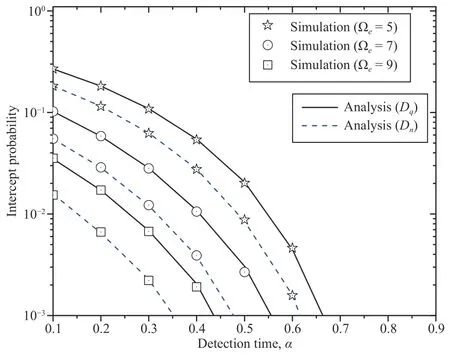
Fig.8.The effects of the detection time and channel estimation correctness on the IP.
Figs.4–6 show how the altitudes of the UAVs affect the throughputs ofDqandDnand the DP for the UE with different values of the channel estimation correctness when the numbers of antennas areM=2 for the GBS,A=2 for the UR,V=2 for the UJ,andK=2 for the UE.Several observations can be made.First,in Fig.4,whenhRis small,the throughput is low because when the altitude of the UR is low,obstacles are densely present,i.e.,the probability of NLoS conditions is high,which leads to low throughput.The throughput increases when the UR flies higher.However,once the UR flies above a certain moderate altitudehR=20,the throughput will again decrease,which is reasonable because a higher altitude also leads to greater path loss.Furthermore,the throughputs ofDqandDnunder the NOMA scheme outperform those under the orthogonal multiple access(OMA)scheme because the UR sends information only to eitherDqorDnin time blockTin the OMA scheme,while the UR simultaneously sends information to bothDqandDnin the NOMA scheme [46].Therefore,the channel capacities ofDqandDnunder the NOMA scheme are higher than those under the OMA scheme.This observation also applies for the remaining simulations.
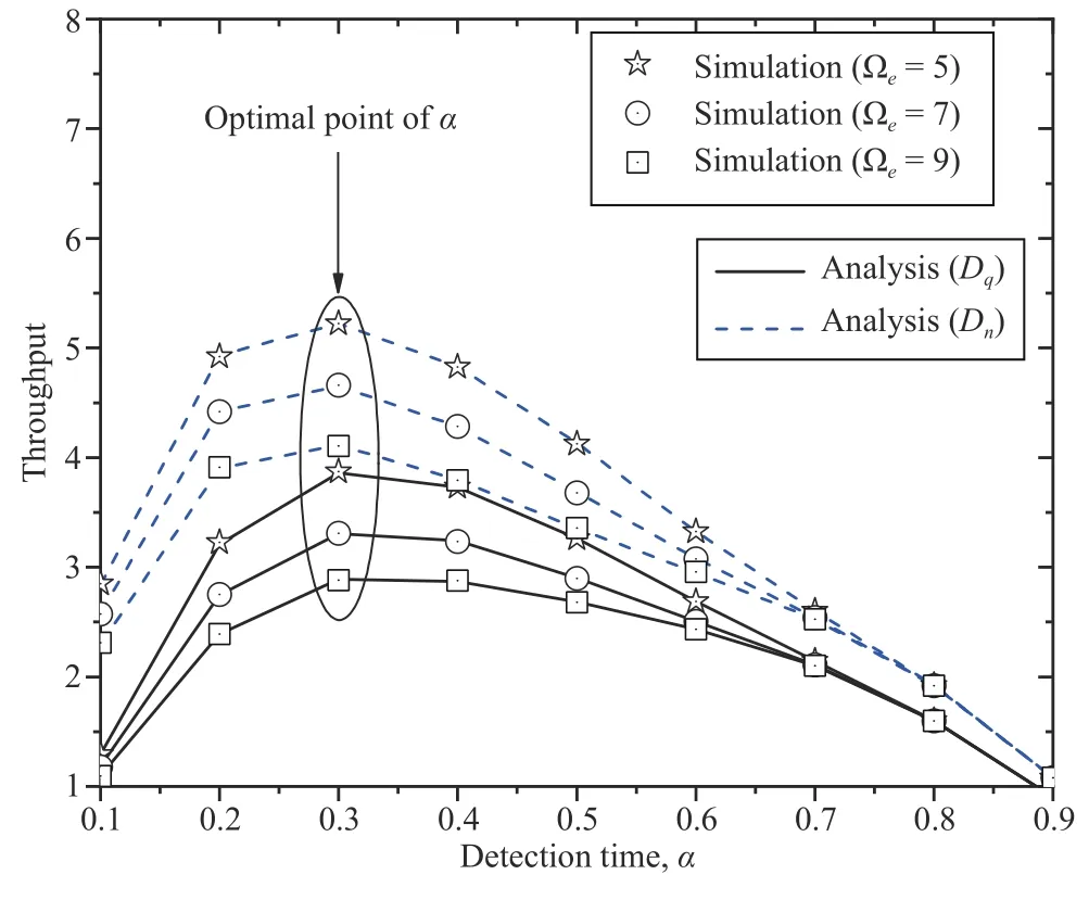
Fig.9.The effects of the detection time and channel estimation correctness on the throughput.
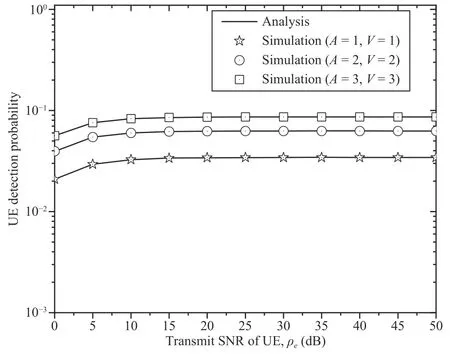
Fig.10.The effects of the transmit SNRs and the numbers of antennas of the UR and UJ on the DP.
Second,Fig.5 shows the effects ofhJandhRon the DP when the coordinates are set toDq(20,25,0) andDn(10,15,0).The DP is better with a higherhRbecause when the UR is closer to the UE,the DP for the UE will improve.However,a higherhRalso leads to lower throughput (refer to Fig.6).Thus,there is a trade-off between throughput and secrecy performance.Therefore,based on a moderate altitudehR,Fig.6 shows the optimal power for maximizing the DP at a moderatehJ.Similar to Fig.4,either an excessively low or excessively high altitude of the UJ leads to a small probability of detecting the UE because of the high path loss.These results are consistent with Remark 1.Therefore,by using Algorithm 1 to determine the optimal altitudeshRandhJ,the system and secrecy performance can be improved.
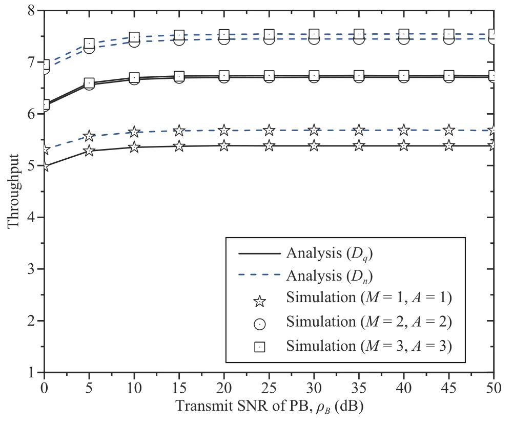
Fig.11.The effects of the transmit SNRs and the numbers of antennas of the GBS and UR on the throughput.
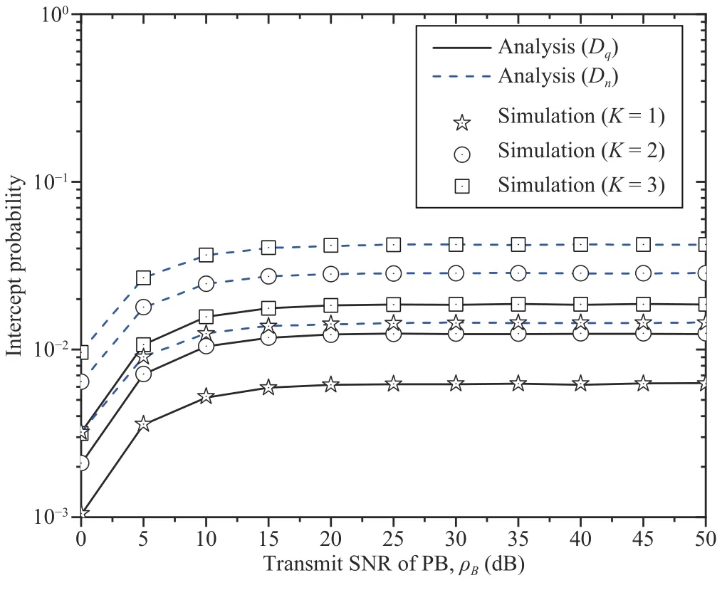
Fig.12.The effects of the transmit SNRs and the numbers of antennas of the UE on the IP.
Third,the throughput of and DP for the UE become less desirable as the channel estimation correctness Ωeincreases in both Figs.4 and 6.The main reason is that the channel estimation correctness essentially acts as a source of interference.Correspondingly,a larger Ωeyields lower SINRs at the UR and IDs,leading to low throughput and a low DP.This observation also applies to Figs.7–9.
Figs.7–9 illustrate the DP,IP,and throughput versus the detection time withM=A=V=K=2.First,Figs.7 and 8 show that a higherαleads to a higher DP and a lower IP.As the detection time increases,the UR and UJ have more time to detect the UE,which causes the DP to increase.Simultaneously,the time available for data stealing decreases,which leads to a reduction in the IP.
Second,Fig.9 shows that an increase inαinitially leads to higher throughput;however,once the throughput reaches an optimal value corresponding to a certain detection time(α=0.3),this metric will begin to decrease.This behavior occurs because a longer detection time means that the duration for EH is also increased.With an increasing EH duration,the transmit power at the UR increases,which leads to a higher throughput;however,when the EH time is excessive,the time available for data exchange is too short.As a result,the considered system ultimately has low throughput because the IDs cannot successfully detect their messages.This finding is consistent with Remark 2.Thus,Algorithm 2 can be applied to achieve the optimal throughput for the IDs.
Third,the user throughput of then-th ID is observed to be better than that of theq-th ID in Fig.9.This result can be explained by the fact that the far user suffers a larger path loss than the near user.Fourth,similar to the third observation,the IP ofDqis higher than that ofDn.These two observations also apply for Figs.11 and 12.
Figs.10–12 depict the DP,throughput,and IP as functions of the transmit SNRs of the UE and PB for different numbers of antennas of the GBS,UR,and UE.Several observations can be made.First,the DP,throughput,and IP increase as the transmit SNRs of the UE and PB increase.Second,the throughput initially increases and then remains at a stable level with an increasing SNR because the UR applies the DF relaying technique,i.e.,the end-to-end SINR atDσis the minimum of the SINR at the UR and that atDσ.Thus,as the SNR increases,the EH at the UR increases,which leads to a higher SINR at theσ-th ID.Once the SINR atDσis higher than that at the UR,the end-to-end SINR atDσis simply calculated as the SINR at the UR,i.e.,the SNR of the PB does not impact the throughput.Third,with increases inMandA,the DP improves for anyVandK.Furthermore,the throughput for transmission significantly increases as the number of antennas of the UJ increases for anyKandV.More antennas enable greater diversity gain,which leads to a higher DP and higher throughput.Similarly,the IP increases with a greater number of antennas on the UE forA=2 andM=2.This result indicates that legitimate relaying transmissions are more vulnerable to eavesdropping with a larger number of antennas on the UE.
VII.CONCLUSIONS
This paper has investigated the detection,secrecy,and system performance (i.e.,the DP,IP,and throughput,respectively)of an EH IoT architecture using a proposed form of A-IDS in the presence of an unknown UE.The proposed AIDS includes two components,namely,a UR and a UJ,which cooperate to detect the presence of the UE.The UR applies WPT and the DF technique to send information to the IDs,while the UJ emits artificial noise to support the confidentiality of this communication.Accordingly,a closedform expression for the DP for the UE has been derived.Furthermore,closed-form expressions for the information leakage probability in terms of the IP and the message throughput for a pair of IDs have been obtained.Based on the DP and throughput,an algorithm has also been proposed for determining the optimal altitudes of the UR and UJ to achieve the best throughput subject to a secrecy constraint.The theoretical analyses of the DP for the UE,the IP,and the throughput have been validated against the results of Monte Carlo simulations.The numerical results show that the proposed EH IoT architecture can not only detect an unknown UAV but also achieve satisfactory system performance given secrecy constraints.In our future work,we will investigate a model that utilizes artificial intelligence for UE detection in the presence of other sources of interference for application in broader scenarios.
APPENDIX A PROOF OF LEMMA 1
In accordance with the characteristics of probability,the UE DP can be rewritten as

Furthermore,due to the independence of the RVs,(51)can be expressed as

where χD=−1.By substituting (12),(13),(32),and(33)into (52),we obtain the expression for D given in (53),where ρE=PE/N0.

Based on the CDF defined in (7),the UE DP is derived as shown in (34). ■
APPENDIX B PROOF OF LEMMA 2
By substituting (21),(22),(25),and (26)into (37),the OPs ofDqandDncan be rewritten as shown in (54)and (55),respectively,where−1.Due to the independence of the RVs and based on the properties of probability,the functions (54)and (55)can be formulated as
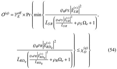
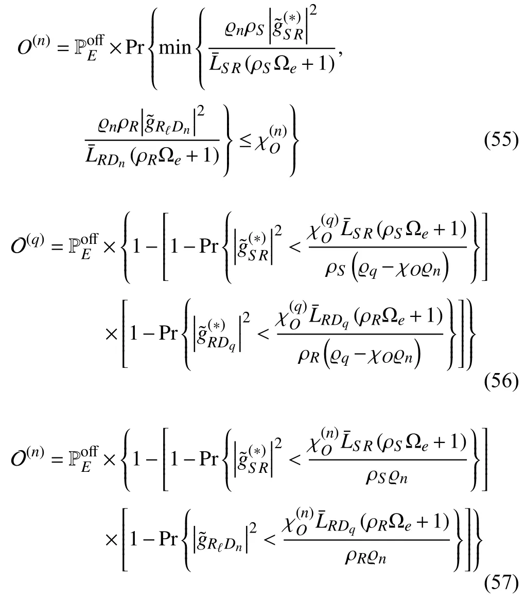
with ϱq>χOϱn;otherwise,O(q)=0.Next,by adopting the CDF defined in (7),the OPs ofDqandDnare derived as shown in (42),where,andare defined as


APPENDIX C PROOF OF LEMMA 3
Similar to Appendix B,by substituting (21),(27),and (28)into (47)and performing some mathematical manipulations,we obtain the probabilities I(q) and I(n),as shown in (62)and(63),whereand ρJ=.In addition,the probabilitycan be obtained by using the same approach applied to obtain (42)as follows:

with ϱq>χIϱn;otherwise,.Here,andare defined as
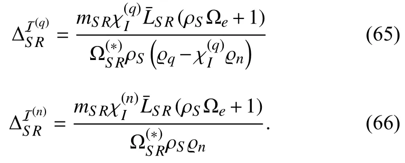
By considering the properties of probability and applying[47,(1.111)],the probabilitiesandcan be rewritten as shown in (67),with ϱq>χIϱn;otherwise,.In this expression,are defined as


We use [47,(3.381.4)] to solve the integral to obtain I(q),as shown in (50). ■
杂志排行
IEEE/CAA Journal of Automatica Sinica的其它文章
- Decentralized Resilient H∞ Load Frequency Control for Cyber-Physical Power Systems Under DoS Attacks
- Adaptive Consensus of Non-Strict Feedback Switched Multi-Agent Systems With Input Saturations
- A Novel Product Remaining Useful Life Prediction Approach Considering Fault Effects
- A New Safety Assessment Method Based on Belief Rule Base With Attribute Reliability
- Data-Driven Heuristic Assisted Memetic Algorithm for Efficient Inter-Satellite Link Scheduling in the BeiDou Navigation Satellite System
- Static Force-Based Modeling and Parameter Estimation for a Deformable Link Composed of Passive Spherical Joints With Preload Forces
