Experimental study of the effect of slotted blades on the Savonius wind turbine performance
2021-08-14DominicusDnrdonoDwiPrijTjhjnZinlArifinSuyitnoSuyitnoWiwEndrJuwnAdityRioProwoCturHrsito
Dominicus Dnrdono Dwi Prij Tjhjn , ,Zinl Arifin ,Suyitno Suyitno ,Wiw Endr Juwn ,Adity Rio Prowo ,Ctur Hrsito
a Department of Mechanical Engineering, Universitas Sebelas Maret, Surakarta, Indonesia
b Vocational School of Mechanical Engineering, Universitas Sebelas Maret, Surakarta, Indonesia
Keywords:Reynolds number Slotted blades Savonius wind turbine
ABSTRACT This study investigates the effect of Reynolds number on the performance of Savonius wind turbine with slotted blades.The turbine performance investigation was based on the torque coefficient (Ct),power coefficient (Cp),and tip speed ratio (TSR).The experiment used two number of blade configuration,blade overlap ratio of 10%,12.5% and 20%,slotted position of 15%,20%,25% and 35%,and also slotted gap width of 3 mm,5 mm,7 mm,and 9 mm.The wind speed carried out in this experiment are 5.94 m/s,6.46 m/s,6.99 m/s,and 7.27 m/s,which are generated from the fan blowers as a wind source.The Savonius turbine with 10% overlap ratio shows the best performance.The highest Cp obtained is 0.138 by the variation of a 3 mm gap with Re of 1.44 × 10⁴ and 0.526 TSR .
Increasing energy request causes conventional energy to become scarce and more expensive.Renewable energy sources are an alternative power plant to reduce fossil fuels and air pollution resulting from carbon dioxide emissions.This condition shows that there is a need for alternative energy resources.Therefore,many countries in the world utilize technology to produce clean and renewable energy that is always available in nature to fulfill high electricity needs [ 1,2 ].Some renewable energy resources are wind energy,solar energy,biomass energy,and geothermal energy [ 3,4 ].The wind is abundant and accessible as an alternative energy resource,yet it is only incorporated a little in Indonesia.Therefore,Indonesia’s government plans to divert 23% of national energy resources to renewable energy in 2025 [5] .However,wind energy has several drawbacks,namely high installation costs and the need for strong winds to produce electricity.
To produce electrical energy,wind kinetic energy is converted with a generator’s help [6] .Wind turbines have two types based on shaft position to the wind direction that is vertical axis wind turbine (VAWT) and horizontal axis wind turbine (HAWT) [ 7,8 ].VAWT wind turbines are more widely used for small-scale turbines because they have several advantages:their performance is independent of wind direction,easy to maintain,and can also operate at low wind speeds [9–12] .A VAWT Savonius is a wind turbine with a high self-start and can operate at low wind speeds [13] .It also has high torque,low investment costs,and has low noise[ 14,15 ].However,the Savonius wind turbine also has the disadvantage of low efficiency,which makes it very interesting to study further [16] .Several studies have been conducted to improve turbine performance from various aspects such as blade shape,blade number,overlap ratio,end-plate,geometry,and inlet speed [17–19] .
Various blade geometry shape of Savonius wind turbines have been investigated by some researchers.During the last three decades the Savonius blade design is continuously changing to maximize the harvesting of available wind energy and to increase the performance of the wind turbine.The first design of Savonius rotor is two semicircular blades developed in 1925 by Finnish engineer Sigurd Johannes Savonius.Savonius declared that his turbine maximum power coefficient of 0.31 [20] .The later investigation using wind tunnel conducted by Simmons and Bodek [21] found that the maximum power coefficient is 0.14 at tip speed ratio of 0.7.Newman also explored the conventional Savonius wind turbine.He found that the maximum power coefficient of the turbine ranges from 0.17 to 0.30 [22] .
The number of blade has an influence on the Savonius wind turbine performance.Saha et al.[17] experimented by varying the blade number on a single,two,and three stages Savonius rotor system shown at Fig.1.The rotor used in the experiment was the semicircular type.The Savonius turbine with two blades shows a higher power coefficient than the turbine with three blades.After the airflow hits one of the blades,the airflow will be bounced to the next blade and creates negative torque in the three-bladed rotor case.Therefore it is concluded that Savonius with two blades has the best performance.

Fig.1. Solid models of single-,two-and three-stage rotor systems [17].
Another research about the number of Savonius rotor blade was also done by Alom et al.[23].The Savonius with two,three and four blades were analyzed numerically by using computational fluid dynamics software.The flow visualization on the turbines showed a flow recirculation formation behind the turbine system with three and four blades.This caused air flow circulation around the shaft and created vortex in the downstream of three and four bladed turbine systems.However the phenomena did not happen on the two-bladed Savonius turbine;therefore,it produced a better power coefficient than the other turbine systems [23,24].The maximum power coefficient achieved by the two-bladed Savonius system was 0.34.
Sheldahl et al.[25] studied the influence of blade number on the Savonius wind turbine performance using a 4.9 m × 6.1 m low speed wind tunnel.The Savonius turbines with two and three buckets were tested at nominal freestream velocities of 7 and 14 m/s,corresponding to nominal Reynolds number per meter,Re/m,of 4.32 × 10⁵and 8.67 × 10⁵,respectively.The turbines blades had gap spacing (S/D) of 0.0,0.10,0.15 and 0.20.The study showed that two-bucket configurations have better aerodynamic performance than the three-bucket.The aerodynamics performance of the turbine generally improves with the increasing Reynolds number.The result also showed that the blade gap withS/D0.10–0.15 yields optimum performance.In addition,the aspect ratio also affects the performance of Savonius wind turbines through its aerodynamics.
Aspect ratio (ARheight/diameter) of wind turbine is one of important factor to design different scales of a small wind turbine.The other geometry parameters of wind turbine are overlap ratio(δe/d) and gap ratio (Gp/d) [26–28],as it can be seen in Fig.2.The previous study shows that the use of aspect ratio 0.88 and overlap ration 0 has the highest power coefficient of 0.165[29].

Fig.2. Conventional Savonius turbine configuration.
To improve the performance of the turbine can be done by adding an overlap ratio.Nakajima et al.[30] explained that the overlap ratio positively impacts the turbine performance by governing the air flow on the rotor during operation Fig.3.The gap of the blade helps to restore the pressure on the returning bucket concave side by channeling the air flow from the advancing bucket.The restoring pressure on the returning bucket increases the positive torque of the Savonius wind turbine.According to Fujisawa[31] Savonius wind turbines with an overlap ratio between 10%–15% produce maximum power coefficient [9,31].The other studies on overlap ratios with variations in the number of blades.The use of an overlap ratio aims to increase the turbine’s ability to spin by increasing the pressure on the concave side of the returning blades[32].The studies show that the turbine performance with overlap ratios of 10 has high efficiency with the number of blades of 2 and 3 on wind speeds of 7 and 14 m/s [25,33].
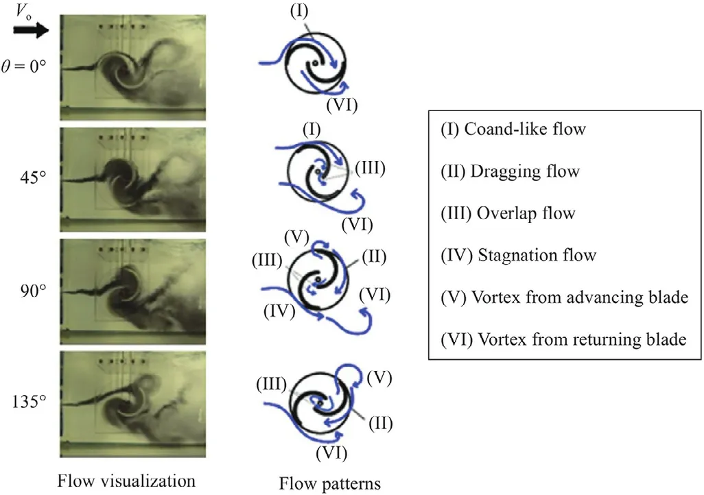
Fig.3. Flow visualization of Savonius rotor [9].
When the wind pounds the rotor of the Savonius wind turbine,the air will flow to all directions.Therefore,affects the turbine performance.Jeon et al.[34] studied experimentally the effect of the various size end plates addition to the Savonius helical turbine to increase the aerodynamics performance shown at Fig.4.The end plates addition aims to restrict the air flow from exiting the rotor,thus increase the drag force on the rotor.There are five different blockage ratios of end-plate,covering from 3% to 8.3%.By adding the end plates on both upper and lower of the rotor,the power coefficient of the turbine is significantly increased up to 36% compared with no end plates.It is also found that the power coefficient linearly increases in proportion to the end plate area.

Fig.4. Various of end plates [34]. a No end plate. b End plate #1. c End plate #2. d End plate #3. e End plate #4.

Fig.6. Venting slot and blade dimensions [37].
Another study about end plate also have been done by Akwa et al.[9].It is revealed that adding the end plates causes the Savonius turbine to operate more efficient at higher tip speed ratio as shown Fig.5.The optimal size of the end plate should have a diameter equivalent to 1.1 times the rotor diameter and negligible thickness,relative to the turbine height.A very high diameter and thickness of end plate can dramatically increase the rotor inertia.The addition of an end-plate with a size of 1.1 turbine diameter produces an increased power coefficient due to the effect of blocking airflow thereby increasing the transfer of momentum [35].The addition of end-plates can increase the efficiency of Savonius wind turbines by up to 36% compared to turbines without end-plates.An increase in the turbine power coefficient due to the flow of air that is in the concave side held by the end-plate,so that make the pressure higher than the convex side during the turbine rotation[18,36].
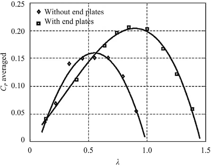
Fig.5. End plates effect on the performance [34].
The improvement of the Savonius wind turbine is also done by modifying the blade.One of the modifications is by making a venting slot on the blade [37].The slots are chamfered to direct the air flow (Fig.6) and as a result it will decrease the thrust force and reducing the negative torque of the returning blade.The result shows that the capped (end plate) and vented blade has slightly better performance than without venting slot [38].
The idea of reducing the negative torque is also done by pasting a small raxine-type cover pasted in the concave side of the blade,which is purposely holed (Fig.7).The raxine-type cover creates a kind of one-way valve on the blade.When the wind is facing the concave side of the blade,the air cannot flow through the hole because the raxine cover will be attached to the blade surface.However,the hole will allow the air to flow from convex side to theconcave side.The mechanism will reduce the pressure on the con vex side but increase the pressure on the concave side.This will considerably reduce the negative torque on the rotor.A twobladed Savonius rotor with twisted blade and valve system can achieved power coefficient maximum of 0.31 [39].
In a study conducted by Harsito et al.[40] and Nugroho et al.[41] shows that the use of slotted blades can improve turbine ef ficiency with configuration position of slotted blade.The results showed that turbine power increased by 15% compared to con ventional turbine.Another study about slotted blades effect was done in computational fluid dynamics (CFD) simulation [42].The simulated turbine configuration on the study is 25%,40%,60%,and 75% slotted position.The result shows that the highestCPvalue is in the slotted position below 40% [43] (Fig.8).The channeling air flow through the slot gap,from the convex side of returning blade to the concave side of advancing blade,helps to reduce the pres sure on the convex side and increase the pressure on the concave side.Therefore,the positive torque increases.
This study aims to investigate the effect Reynolds number on the performance of Savonius wind turbines with slotted blades which is able to increase power performance of wind generator.Turbine performance can be measure from the value of the torque coefficient,power coefficient and tip speed ratio.Coefficient of power is obtained from the comparison between the mechani cal power-generated by the rotor with the mechanical power con tained in wind energy.Coefficient of torque is obtained from the actual torque compared to the theoretical torque.While the tip speed ratio is the ratio of the tip rotor speed to the free wind speed.
Table 1 shows the turbine geometry used in this study.A model of slotted blades Savonius wind turbine was designed with Solid-works (CAD) and fabricated in ATMI Duta Engineering Surakarta,Indonesia.The geometry of the Savonius turbine with semi-circular blade is selected because of its design simplicity.The turbine pa rameters are determined based on the previous work by Mon telpare et al.[14].The selected configuration,such as number of blades,endplate size,and overlap ratio are also agreed by most au thors of the previous works.The addition of endplates is intended to block the flow of air out of the upper and lower turbines,so that the concave blades generate greater force.The choice of alu minum material was chosen because of its light weight and easy processing for machining.

Table 1 Savonius wind turbine geometry.
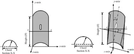
Fig.7. Valve-aided semicircular and twisted blades [39].

Fig.8. Vector velocity [43].
The geometry design refers to the research conducted by Montelpare et al.[14] and the modification on blades by adding slotted blades in refers to the simulations by Alaimo [32].The slotted blade modification used in this study is shown in Fig.9,where Fig.9a is used as a benchmark for making the proposed slotted blades configuration,see Fig.9b.Slotted blades are obtained by cutting and offsetting the outside of the blade by shifting it towards the center of the blade,which is different from the configuration done .
Then,at this present study,the turbine uses the 2 bladed configurations,overlap ratio of 10%,12.5% and 15%,with a slotted position (f) 15%,20%,25%,35% and a gap width of 3 mm,5 mm,7 mm and 9 mm.The wind speed variations carried out in this experiment are 5.94 m/s,6.46 m/s,6.99 m/s and 7.27 m/s as shown at Table 2.Fan blowers are used as sources of wind because they can represent environment that resemble the actual condition.The position of the turbine to get a uniform wind speed is set at 1 m in front of the blower fan [44].Meanwhile,to get the value of the coefficient of power and torque,a prony brake system is utilized[45].

Table 2 Experimental variations.

Table 3 Wind velocity and corresponding Reynolds number.
The experimental set up of the Savonius wind turbine study is shown in Fig.10a.The wind source in this experiment uses fan blowers with the configuration shown in Fig.10b.To get stability and uniformity of airflow,the distance between the fan blowers and the turbine is set as far as 1 m [25,44].
The data taken in the experiment were the air flow velocity,the turbine rotation speed (rpm),and the force reading on the prony brake system.The data acquisition procedure is as follows:
(1) The experimental setup is shown in Fig.10a.The distance of the blower surface to the turbine axis is 1 m.
(2) The fan blower is turned on,and wait for five minutes to make sure that the wind is blowing steadily.Furthermore,to determine the average wind velocity,the velocity is measured on 9 points (Fig.11) using a hand-held anemometer.The data are taken five times in thirty seconds intervals.
(3) The turbine rotation speed is measured using a tachometer and taken ten times for every loading.This tachometer is connected to the bottom of the rotating turbine shaft.
(4) A digital balance is used to measure the net tangential force on the pulley of the prony brake system,as depicted in Fig.12.Based on the tangential force obtained,the torque that works on the wind turbine will be generated by doing calculations.
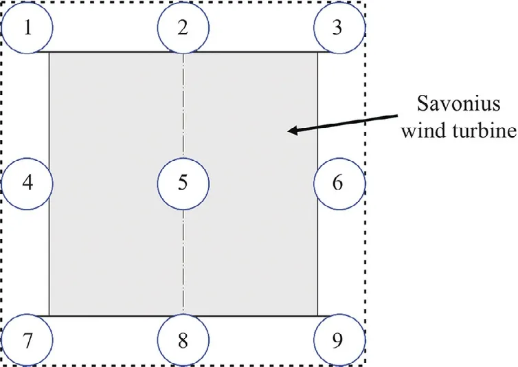
Fig.12. Prony brake system.
(5) The load on the prony brake system gradually increases,starting from 5 g until the turbine stops rotating,with a 5 g increment.Rotation speed and digital weight balance data are taken for each load with ten repetitions for each variation.
(6) Base on the data taken,the torque coefficient (Ct),power coefficient (Cp),and the tip speed ratio (TSR/λ) are determined.
TheCprepresents how much energy of the wind can be converted by the turbine rotor.It can be defined as the ratio of turbine output power to the available power of the wind.TheCprelation to the other parameters can be written in the following equations:

The turbine output powerP(W)is the result of the torque (TT)of the prony brake system multiply with angular velocity (ω) of the rotor shaft.The torque is equal toTTFe×Re,whereRe(radius effective) is determined from pulley radius added with rope radius.Whereas the effective force(Fe)is defined fromFeFs−w,Fsis the reading on the digital weight balance while the pulley is rotated anti-clockwise.
The torque coefficientCtis defined as the ratio of actual torque working on the rotor to the theoretical torque.The torque coeffi-cient is formulated as follows:

Fig.9. Turbine design: a conventional, b with slotted blades.

Fig.10. a Experimental set up test bench; b blower fans 2 × 2 configuration.

whereTTrepresents the actual torque produced by the rotor.
The other parameter is the tip speed ratio (TSR/λ) is the result of linear velocity on the tip of the rotor divided by the wind free stream velocity.The tip speed ratio is formulated in the following equation:

whereRis the rotor radius (m),Nis the rotor rotation speed (rps),Vis the wind free stream velocity (m/s),andωis the angular velocity of the rotor (rad/s).
TheCpandCthave a linear relationship.It can be shown by substituting Eqs.(2) and (3) to Eq.(5).The relationship is as follows:


Fig.11. Schematic of wind speed data collection point.

This section discusses the results obtained from the turbine performance study.The effects of slotted blades and Reynolds number are discussed in the next sub section.The wind velocity set up and the corresponding Reynolds number for the experiment is presented in Table 3.Wind speed is measured using an anemometer at 9 measurement points which represent the entire test area of the turbine as shown in Fig.12 with the measurement position 1 m in front of the blower fan.

Fig. 13. a Power coefficient on overlap ratio 10%,Re1.44 × 104.b Torque coeffi-cient on overlap ratio 10%, Re1.44 × 104.
The Reynolds number is calculated by using Eq.(9)

where,the dynamic viscosity,μ,density of air,ρ,and rotor diameter,Dare taken as 1.983 × 10⁻⁵kg/(m·s),1.18 kg/m3and 0.04 m respectively.
The power coefficient of the Savonius wind turbine with the position of the slotted blades is shown in Fig.13a.The power coefficient increases with the rise of tip speed ratio and decreases after reaching the maximum power coefficient at the optimum tip speed ratio [46].This happens when the turbine rotation speed achieves the certain velocity,the momentum is transferred from the turbine to the airflow,therefore reduces the moment that can be extracted by the turbine rotor [9].The highest power coefficient attained is 0.109 in the position of slotted blades 15% atTSR0.530.On the other hand,the highest torque coefficient is 0.320 atTSR0.099 as shown in Fig.13b.This is in accordance with previous studies where a 10% overlap ratio can distribute fluid flow quickly from the concave side of the advancing blade to the concave side of the returning blade so that the produced positive torque enhance [31].The addition of slotted also affects the pressure difference through zones on both sides of the Savonius turbine [9].

Fig. 15. a Power coefficient on overlap ratio 15%,Re1.44 × 104.b Torque coeffi-cient on overlap ratio 15%, Re1.44 × 104.
Figure 14 shows the power coefficient of the Savonius turbine with a variation of the slotted position of 15% obtaining the highest value at a wind speed of 5.94 m/s with aCpof 0.100 at aTSRof 0.453.Wind turbines with a 15% slotted blade position can increaseCpby 5.7% compared to conventional Savonius turbines.The same thing also happened to the 10% overlap variation,because the wind speed was more than 5.94 m/s,the wind flow in the overlap area collided due to a gap in the concave blade.Thus,the wind flow does not fully flow towards the concave blades (returning blades).
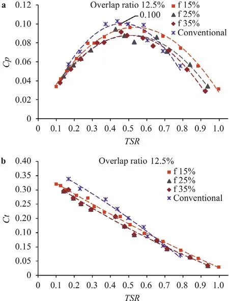
Fig.14. a Power coefficient on overlap ratio 12.5%, Re1.44 × 104. b Torque coeffi-cient on overlap ratio 12.5%, Re1.44 × 104.
The power coefficient on the turbine with the slotted blade position 25% and 35% shows a decrease compared to other turbines both in the condition of the overlap ratio of 10% or 12.5%.This is because the slotted blade that moves away from the turbine root or closer to the middle of blades will reduce the energy utilization of the airflow captured by the concave blade.This is not proportional to the reduced negative torque on the slotted blade returning the convex blade.Based on the data,wind turbines with a slotted blade position of 15% can increase power coefficient values up to 15.9% compared to conventional Savonius turbines and has the best performance.
Figure 15 shows the results of the experimental power coeffi-cient with the slot position (f) 15%,25% and 35% at an overlap ratio of 15%.The figure shows the highestCpat (f) 15% with aCpof 0.980 atTSR0.453 withRe1.44 × 104.The conventional Savonius turbine gets aCpof 0.103 at aTSRof 0.494.However,the turbine with an overlap ratio of 15% does not show an increase in theCp.Besides,the variation of turbines with slotted (f) blade 25% and (f)35% shows theCpobtained is also decreased compared to conventional wind turbines.This is because the fluid flow that hits the turbine cannot be fully utilized to drive the turbine,at (f) more than 15% there is a fluid flow that breaks the turbine through the slotted gap.This is not proportional to the reduced negative torque on the slotted blade returning the convex blade.The phenomenon that occurs is the drag coefficient in the form of a barrier object experiencing fluid flow losses so as to make drag force decrease on the concave blade side.Based on tests conducted,the data shows that in this study the bestCpwere obtained at the lowest wind speed of 5.94 m/s.This is because when the wind speed is more than 5.94 m/s,the wind flow in the overlap area collides due to a gap in the concave blade.Thus,the wind flow does not fully go to the concave blade (returning blade).
Based on the results of previous experiments showed that the use of a 10% overlap ratio in Savonius wind turbines showed the most maximum results.In addition,the position of slotted blades between 15 and 35 can improve turbine performance.This is consistent with the results of previous studies conducted by Agung et al.[41].Then an experimental test is then performed to see the effect of the width of the slotted gap with an overlap ratio of 10% and the position of the slots between 15% and 35%.
To find out the performance of Savonius wind turbines,the value of the power coefficient was analyzed.Some energy cannot be absorbed by the turbine when the fluid passes through it.Based on the results obtained in Fig.16,we can see that the value of the coefficient power on the variation of 3 mm slotted has the highest value in all Reynolds number conditions.A similar trend occurred in all conditions of Reynolds Number when the value of theTSRincrease,Cpwill further increase to the maximum point after the TSR reaches the optimum valueCpwill decrease with increasing the value ofTSR,so it forming a parabolic curve [46].The highestCpis found in the variation of 3 mm slotted with the conditionRe1.44 ×104which is 0.138 atTSR0.526.
The next step is to analyze the value of the torque coefficient on all variations with differentReconditions.Based on the results of the study the value ofCtandTSRis inversely proportional to the value ofCtdecreases when the value ofTSRincreases [26].This happens because the testing process is done using a prony brake system that is given a gradual loading until the turbine stops spinning.The resulting torque coefficient value can be seen in Fig.17 where the best torque coefficient value is in the variation of 3 mm whenRe1.44 ×104which is 0.409 atTSR0.118.
Turbine performance has a maximumCtat 3 mm gap variation because the fluid flow in the concave blade still leads to the other concave blade and increases positive torque at the convex blade.Due to the addition of Slotted,the flow that hits the convex blade can pass through the blade and does not prevent the blade from moving forward and reduces the drag force,thereby increasing the blade’s performance.

Fig.16. Coefficient power vs tip speed ratio of Savonius wind turbine with various slotted blades and different Reynolds number.

Fig.17. Torque coefficient vs tip speed ratio with various slotted blades and different Reynolds number.
Contrastingly,turbine performance decreases when the slotted gap gets wider,this happens because the wind flow on the concave side of the returning blade collides with the wind flow through the slotted gap,thus reducing the positive torque on the returning blade.The phenomena are shown in Fig.18.At a small slot gap,such as 3 mm,the wind flow that causing negative torque on the convex side of the returning blade reduces by channeling the wind through the gap.At small gap,the channeling wind is able to reduce the negative torque,but does not affect significantly to the positive torque on the returning blade (Fig.18b).On the other hand,at wider slot gap (5,7 and 8 mm) especially at highReand lowTSR,the channeling wind flow through the slot gap,over powers the wind flow through the blade overlap,thus reducing the positive torque on the returning blade,as it seen in the Fig.18c,18d and 18e.

Fig.18. Illustration of wind flow for Savonious: a conventional; b 3 mm gap; c 5 mm gap; d 7 mm gap; e 9 mm gap.
This research has been successfully carried out with the configuration of the slotted blades on the Savonius turbine.Based on the results and analysis,it can be concluded that the addition of slotted blades can improve the performance of Savonius wind turbines.The highest power coefficient value is in the variation of 3 mm slotted with the conditionRe1.44 × 104which is 0.138 and has increased by 34% from conventional Savonius wind turbines.Slotted blades reduce the airflow hitting the convex blades through the gaps thereby reducing negative torque and with a 3 mm gap it increases the power coefficient on the Savonius wind turbine.
DeclarationofCompetingInterest

The authors declare no conflict of interest.
Acknowledgement
This research was funded by Universitas Sebelas Maret,grant of PNBP with contract number 452/UN27.21/PN/2020.
Supplementarymaterials
Supplementary material associated with this article can be found,in the online version,at doi:10.1016/j.taml.2021.100249.
杂志排行
Theoretical & Applied Mechanics Letters的其它文章
- A geometry-based framework for modeling the complexity of origami folding
- Why neural networks apply to scientific computing?
- Analytical solutions for inflation of pre-stretched elastomeric circular membranes under uniform pressure
- Computing mean fields with known Reynolds stresses at steady state
- Fundamental kinematics laws of interstitial fluid flows on vascular walls
- Analytical and numerical studies for seiches in a closed basin with various geometric shapes of longitudinal section
