A geometry-based framework for modeling the complexity of origami folding
2021-08-14SamuelSchulmanXinNing
Samuel Schulman,Xin Ning
Department of Aerospace Engineering, The Pennsylvania State University, University Park, Pennsylvania 16802, USA
Keywords:Origami folding Framework Miura-ori
ABSTRACT This paper presents a quantitative framework to analyze the complexity of folding origami structures from flat membranes.Extensive efforts have realized intricate origami patterns with desired functions such as mechanical properties,packaging efficiency,and deployment behavior.However,the complexity associated with the manufacturing or folding of origami patterns has not been explored.Understanding how difficult origami structures are to make,and how much time they require to form is crucial information to determining the practical feasibility of origami designs and future applications such as robotic origami assembly in space.In this work,we develop this origami complexity metric by modeling the geometric properties and crease formation of the origami structure,from which it outputs crease and pattern complexity values and a prediction of the time to complete the pattern assembly,based on the characteristics of the operator.The framework is experimentally validated by fabricating various Miura-ori origami paper models.
Origami,an ancient form of art,has rapidly evolved into an engineering design approach in aerospace,mechanical,civil,biomedical,and many other fields.Its capability of transforming materials and structures into different two and three-dimensional configurations is not only of fundamental scientific interests,but also has enabled a wide variety of engineering applications that were previously infeasible.This shape-transformative characteristic of origami has stimulated a rich collection of fundamental studies on its mechanics including stability,dynamics,folding and deploying behavior,mechanical properties,and numerical modeling [1–7] .Recent advances have realized novel applications ranging from largescale solar arrays,space telescopes,spacecraft sunshields,and antennae to micro-scale tissue scaffolds,electronics,and microelectromechanical systems [8–12] .Engineering with origami has further promoted research in active self-foldable materials,metamaterials with exotic mechanical properties,soft robots and compliant mechanisms,stiff energy absorbers,and bulletproof shields [2,8,13–28] .
Origami engineering has moved farther away from simple shapes to more complex geometries to serve more advanced design purposes.For example,Freeform Origami is a recently developed method to achieve highly complex origami structures based on sets of desired design objectives [29–31] .As more complex origami structures are designed,using computer software or otherwise,they become increasingly intricate and thus require more time and effort to be physically produced.Although intricate origami designs may have advantages,their manufacture could be too challenging to be practical for some applications.Understanding how difficult these structures are to make and how much time they require to form are crucial to the evaluation of origami designs and their manufacture.Despite the extensive study of origami patterns and materials,in recent years,a fundamental understanding of the complexity of folding origami structures has been overlooked.
The work presented here provides a quantitative framework based on origami geometry and topology to understand and analyze those production effort s,which engineers can utilize when comparing different designs.This framework produces a set of metrics which describe the complexity of origami patterns as they are folded from a two-dimensional flat sheet.Pattern complexity describes the origami structure before folding begins and assigns a complexity value independent of folding orders,techniques,or skills.Dynamic crease complexity refers to the relative effort s of folding one crease to folding others as the creases are sequentially made and the structure changes shape.This framework currently takes into consideration only intrinsic geometric and topological properties of origami,such as folding pattern and folding order to determine the complexity of creating the structure.As future advances in origami engineering identify new sources of complexity,this framework can be expanded upon.This paper presents present our efforts to quantify crease complexity and translate it to a useable,practical metric that will benefit future engineering endeavors with origami.
To present the current status of relevant research,we begin with a brief literature review.It should be noted that,although engineering origami is being extensively studied,the practical difficulty and complexity of folding origami structures have been scarcely studied in depth.
Halkjelsvik and Jørgensen [32] performed a comprehensive review on performance time predictions that integrated research from engineering,management science,and psychology.Their results,those which related to our research,mainly discussed sources of error in predicting the time of accomplishing a task by both an observer and a subject.This was a valuable insight into possible sources of error that could be encountered.However,due to the technical focuses and interests of this work,it did not present a method of predicting the amount of time to complete a task nor a measure of the complexity of a task.This paper,like many others from the field of psychology,assigned an arbitrary scale for complexity and focused heavily on subjective,selfreported results of both complexity and estimations of time.The gaps in previous research,as discussed both here and in the following paragraphs,reinforced the need for an objective quantitative determination of these metrics.
An early attempt at quantification for comparable tasks to origami came in a paper by Richardson et al.[33].Then,they lamented,“a general lack of understanding as to what factors affect assembly task complexity and the use of diagrammatic instructions”,which follows remarkably closely to the need we have ascribed to origami research.Part of their preliminary quantification stemmed from experiments conducted by Novick and Morse[34],which showed that reducing the number of steps in an assembly process,increased the accuracy of the assembler.To analogize to origami,an assembly process and order is equivalent to the act of folding the membrane and the order in which the folds are made.They then identified and defined seven task variables each of which they posited might have a contribution to the efforts of completing the tasks.Three of these,"symmetrical planes","fastening points",and "component groups",are likely not relevant because the folds do not change their relative position on the membrane,are already aligned within the assembly,and do not consist of any subassemblies.The remaining four all have analogues in origami folding."Selections" corresponds to the reduction in complexity as the folds are made over time,"fastenings" corresponds to the complexity of making nodes (the points at which folds meet),"components" corresponds to either the number of folds or the number of nodes that must be made,and "novel assemblies" corresponds to differences in fold length and nonrepetitive patterns.By establishing these task variables,they have made the quantification more universal,applicable to a greater variety of structures.This research was continued by Richardson et al.[35] with further efforts to identify the physical attributes of an assembly which make it more difficult or complex from a cognitive science perspective.Understanding this perspective is important,as that field has specific definitions of complexity which differ from those used in this paper.As will be shown,we utilized a very similar line of logic to Richardson et al.for developing our framework;showing that our approaches to the problem were aligned.A 2013 paper by Kanis [36],cited this paper and asserts there may be significant flaws with similar studies to this and Halkjelsvik and Jørgensen’s concerning the abuse of statistical information and the use of arbitrary complexity scales,among others.The nature of the criteria the researchers set is not seriously called into question,but their attempts to find statistical significance in their experimental data are.This again reinforces the necessity of objectivity,which requires a measurement of task complexity and duration based entirely on the properties of the structure and modified only by the operator’s actions,rather than by self-reported data on arbitrary scales.
The first sources of our literature review dealt primarily with humans as the operators and how they performed the assembly.Structures can be assembled by robots or self-assemble using,for example,motors and actuators.Self-folding methods largely apply energy (e.g.thermal,magnetic,or electrical) to a pre-creased membrane to induce folding or unfolding along the crease lines,without the aid of an operator [37].Stern et al.[37] defined the crease complexity of self-folding origami as relative to the geometry of the folding pattern,the locations of the motors or actuators,and the energy requirements to activate and control them.Therefore,in the case of a self-folding origami structure the crease complexity directly corresponds to a calculation of the energy required at each actuator and has no relation to the human capacity to perform the task,as was the case in the previously discussed papers.The difficulty of completing the entire structure (pattern complexity) then is the sum of the energy required at each actuator.Dynamic crease complexity for robotic assembly may be similarly quantified by the taxation on the operator’s energy or computational systems.A paper on robotic origami folding by Balkcom and Mason [38] described the process of robots analyzing and completing the pattern as node-centric;where the tasks to be completed were the nodes and not the folds.As our calculation for crease complexity is similarly computationally-based,we adopted this node-centric approach into our method;tracking the development of folds as they pertain to the formation of nodes.
In the next few paragraphs,we describe how our framework generates and analyzes a pattern,calculates its complexity,and calculates the time of completion.Figure 1 lays out the schematic for our analysis in three phases:pattern generation (red),static nodal complexity calculation and pattern complexity (blue),and dynamic crease complexity and time calculations (green).
ThePatternGenerationphase takes the geometric information(fold lengths,angles,and tessellations) of the pattern and generates two matrices which describe the position and orientation of the fold lines and the nodes.TheStaticNodalomplexitycalculation determines the initial value of complexity for forming every node in the pattern,prior to any folds being made.This calculation is based on the distance of the node to the nearest corner of the pattern and the number of folds required to complete the node.ThePatternomplexityis the sum of the static nodal complexity of each node and indicates the initial complexity of an origami pattern without regard to folding order,folding technique,or operator skill.
PatternGeneration:TheDynamicCreaseComplexityand time calculations change the values of complexity over time,as folds are successively made according to a specific folding order.This is done by reducing the number of remaining folds around a node,as they are made,and removing the geometric weight if the node has been completed.An experimentally determined time value of a similar task on a smaller scale (initial time) is used to provide a base time for the completion of the first fold of the pattern.From this,the framework compares the complexity values of the rest of the folding pattern as the folds are made to this value to determine the amount of time (T-matrix) each fold in the pattern will take to complete.The framework is implemented in Matlab.
We chose to use the Miura-ori pattern to test and refine our analysis method (Fig.2) [39,40].To generate the geometry of the Miura-ori pattern,four variables are used:lengthis the length of the fold lines (which are all the same),angleis the smaller interior angle of the parallelogram panels formed by the folds,rowsis the number of times the unit parallelogram is flipped and repeated across the top straight side,andcols(columns) is the number of times the unit parallelogram is repeated next to the right angled side.Figure 2 shows the direction of increasing rows in red and columns in blue and marks the angle in green and the equal lengths of two sides in purple.
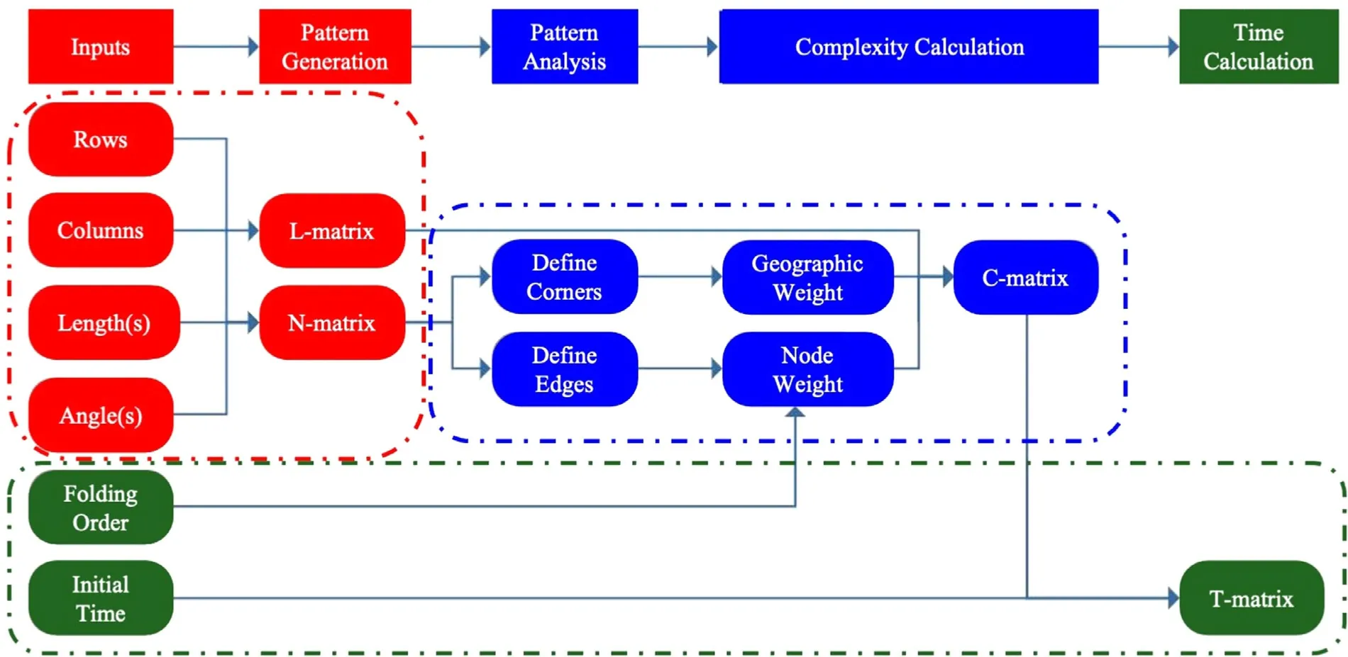
Fig. 1. Schematic of quantitative framework for calculating the complexity of folding origami structures.(For interpretation of the references to color in this figure,the reader is referred to the web version of this article.)
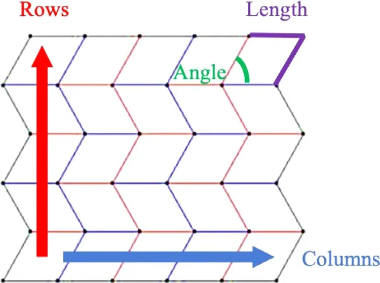
Fig. 2. Geometric input variables.(For interpretation of the references to color in this figure,the reader is referred to the web version of this article.)
From these four values,the framework creates one initial angled line and one initial straight line at the bottom left of the pattern;setting their intersection (a node) as the origin to the coordinate system relevant for later calculations.It then propagates the straight and angled lines to fit the prescribed pattern by generating a matrix of all of the fold lines (L-matrix) and a matrix of their intersecting nodes (N-matrix) and their respective properties.This matrix generation is depicted in Fig.3.The L-matrix stores each line with an ID (which is the order it was placed in the pattern),the length of the line,and the coordinates of both of its endpoints.The N-matrix stores the coordinates of each node and the number of intersecting lines.The matrices are generated simultaneously and the function which creates the nodes checks to avoid duplicates.Table 1 shows the lists of variables used to generate the L-and N-matrices.

Table 2 Summary of matrix definitions.
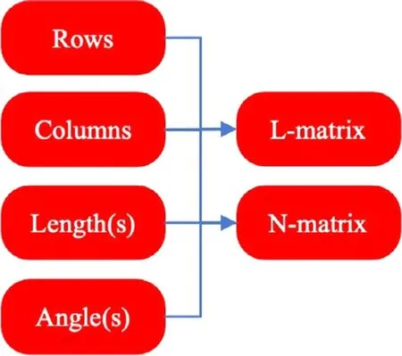
Fig.3. Pattern generation.

Table 1 L-and N-matrices.
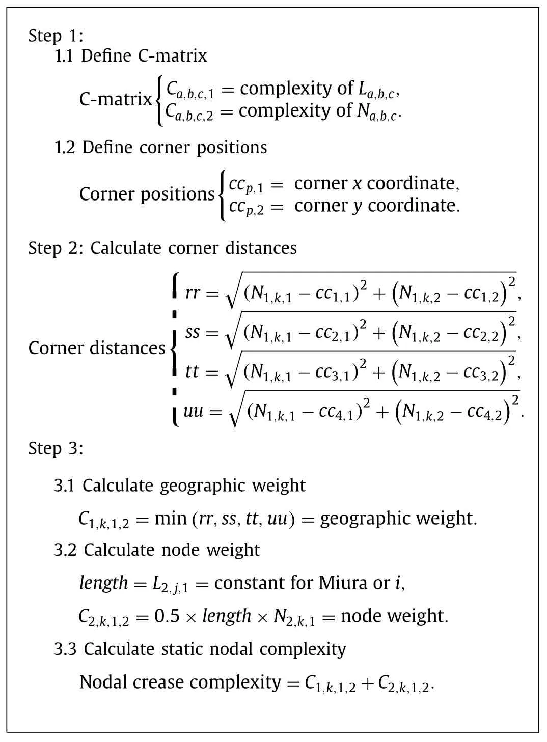
As described previously,theStaticNodalComplexityrepresents the effects of the intrinsic pattern properties on the ability of the operator to fold the pattern,regardless of skill or experience.We quantify this as the relative efforts of completing one task (a node)to completing similar tasks with different parameters.Figure 4 presents the flow of information for the calculation ofStaticNodal Complexity,and the accompanying shaded box shows the spe cific procedure.TheStaticNodalComplexitycalculation determines complexity before any folds have been made,creating a control against which different folding approaches can be equally compared.A matrix of the nodal complexity values in a given structure(C-matrix) therefore has a sum,thePatternComplexity,which represents the complexity of completing the entire structure,independent of operator characteristics.In the framework,the nodal complexity values are based on the geographic position of the nodes relative to the closest corner of the pattern and the number and length of intersecting lines at each node.

Fig.4. Static nodal complexity calculation flowchart.

Fig.5. Dynamic crease complexity and time calculations flowchart.
The C-matrix overlays the L-and N-matrices in its structure to facilitate identification and incorporation of the complexity contributions from each of their respective elements (static nodal complexity equations,Step 1.1).At present,it is understood that a significant contribution to dynamic crease complexity originates from the formation of the nodes.The complexity calculations in this paper thus influence and draw from the C-matrix overlay of the Nmatrix to reflect this.This approach further allows the source of the complexity (i.e.geographic or node weight) in the C-matrix to be easily traced to its dependent element in the N-matrix.Although our research has not identified a direct contribution to complexity from the L-matrix,it is included in in the C-matrix structure,should future research find such connections.
After the C-matrix is created,the pattern analysis section of the framework defines which four nodes on the Miura-ori pattern are corners by checking if the number of intersecting lines equals two(static nodal complexity equation (SNCE) Step 1.2).There would be a similar process for other patterns which define corners generally as the farthest nodes from the center of the structure;which in some cases may be more or less than four.In the Miura-ori case,neither of the two lines which intersect the corner nodes will ever fold,therefore the number of intersecting fold lines is set to zero.The distance of a non-corner node to its closest corner defines the geographic weight of its crease complexity (SNCE Steps 2 and 3.1).
The number of intersecting lines times half of the length of the lines (lengths are stored in the L-matrix) defines the node weight of the crease complexity (SNCE Step 3.2).After defining the corner nodes,the pattern analysis next checks which nodes are edges.Edge nodes are those on the sides of the membrane where two lines mark the border of the membrane and the third connects to a node within the membrane.Similar to the corner nodes,the edge nodes discount the two lines on the border and only count the one intersecting fold line.The static nodal complexity of each node is the sum of its geographic weight and its node weight and the sum of the complexities at all of these nodes prior to folding is called thePatternComplexity(SNCE Step 3.3).
Static Nodal Complexity Equations
As a membrane is folded to create an origami structure,the geometric conditions change over time.The complexity values change after each fold to reflect that the geometry of the membrane has changed and thus the complexity of making subsequent folds may increase or decrease.Figure 5 shows the flow of information,and the bordered box titled dynamic crease complexity and time calculations (DCCTC) shows the procedure of calculating the dynamic crease complexity.The change in complexity values after each fold is calculated by reducing the number of intersectinglines at the two adjacent nodes by one (DCCTC Step 1.3.1).If the node weight is zero,that means all of the folds around the node have been made,so the geographic weight in the C-matrix is reduced to zero (DCCTC Step 1.3.2).The sum of the C-matrix components calculated after each fold is completed is called thedynamic creasecomplexityand is stored in a vectorX.The sum of this vector is thus a dynamic pattern complexity.This simulates the folding process over time and allows this method to be used to estimate how long the folding process will take for any given origami structure,quantitatively how complex different patterns are relative to each other,and whether some folding orders are easier,faster,or more effective than others for completing a structure.
Dynamic Crease Complexity and Time Calculations
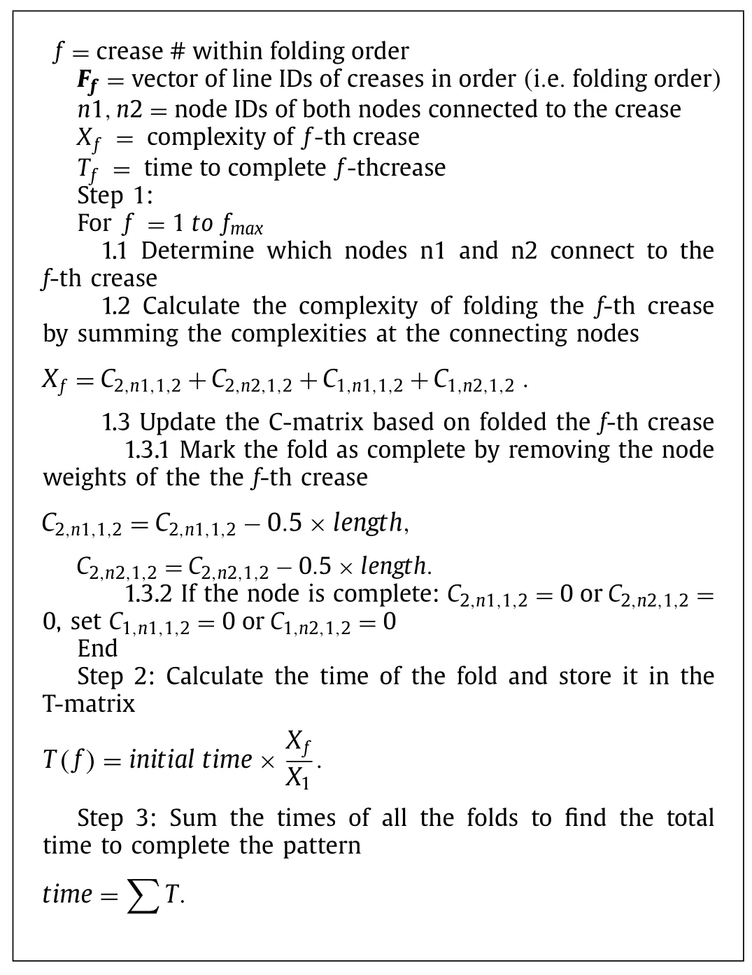
As the C-matrix is generated and adjusted for each fold,an additional vector (T-matrix) is generated to store the time each fold takes to make (DCCTC Step 2.1).Table 2 summarizes the definitions of all matrices used in the framework.The values of time are directly proportional to each other by their complexity values.Their constant of proportionality is determined experimentally,based on the time it takes to complete a smaller or simpler version of the same pattern.For example,the time to complete the first fold of a two row by two column miura-ori could be used to predict the completion time of larger patterns.We demonstrate the soundness of this approach in the first of the experiments we conducted to identify and study sources of complexity in paper origami.
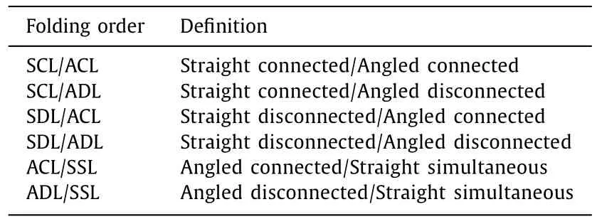
Table 3 Sample folding orders.
Our first study utilizing the framework concerned complexity due to tessellation of the Miura-ori pattern.For this study,the operator was provided pre-printed and cut Miura-ori patterns on printer paper.The operator was well trained on folding paper origami patterns,therefore the time needed for mastering the folding techniques was not included.In the future,it will be interesting to study the learning curves for new operators.The patterns ranged from two rows by two columns (2 × 2) to five rows by five columns (5 × 5) with every permutation in between.Further,three copies of each pattern were made to provide more data points.The folding pattern followed the same rule regardless of the shape of the membrane.The first fold was the mountain fold (red) in the lower left of Fig.2,followed by the unconnected folds up the first column.Next were the connected valley folds (blue) between the first and second columns.Using the orientation as shown in Fig.2,the operator proceeded up each column of unconnected folds from left to right,alternating with going up the intermediate connected folds.This folding order will be referred to as the“columnar”folding order in the next subsection.The operator was timed for how long each pattern took to complete.The average times in seconds to complete each set of three patterns are shown in Fig.6.In Fig.7,a 5 × 5 paper Miura-ori is shown before (left) and after (right)folding.
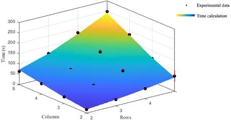
Fig.6. Columnar folding order calculation and experimental data.
The folding pattern as described above was input into our framework along with the geometric information.For this test,all of the patterns had anangleof 60 degrees and alengthof 50.8 mm (2 in).We performed the full calculation of static nodal and dynamic crease complexity for only the 2 × 2 pattern and divided the average time found during the test proportionately across the four folds based on their relative complexity.The time value of the first fold of the 2 × 2 pattern,which is the same first fold for all patterns,was then set as the time value of the first fold for all other pattern sizes.For all subsequent folds that time value was multiplied by the ratio of the complexity of that fold to the complexity of the first fold.Those time values were stored in the Tmatrix,the sum of which was the total predicted time that each other pattern should have taken to fold (see dynamic crease complexity and time calculations).Figure 6 displays the results of this test of our framework on the same scale as the experimental data.We found that our estimates differed by an average of 4% or about 3–4 s from the actual average time of each set of three patterns.
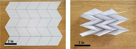
Fig.7. 5 × 5 Miura-ori before and after folding.
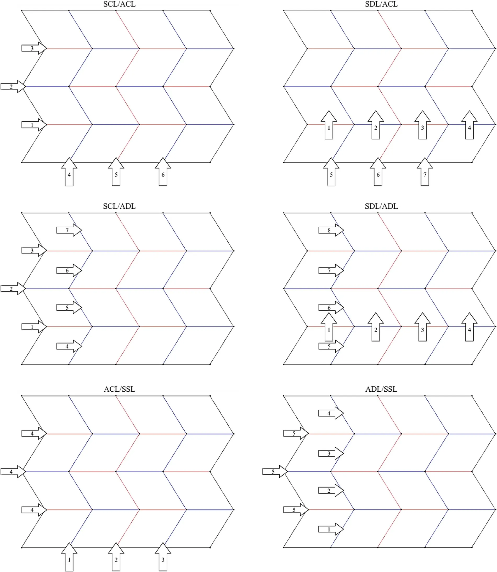
Our second study concerned complexity due to varying the folding order and scaling direction of the Miura-ori pattern.For this study,the operator was provided the same materials and training as in the previous study and tessellation of the pattern was from a 2 × 2 to 4 × 4 Miura-ori pattern.Table 3,below,lists a variety of folding orders on which we tested our framework.The table compares all permutations of straight (S) and angled (A)lines,connected (CL) and disconnected (DL) lines,and the order in which each type of line was completed first (First/Last).A visual representation of folding orders from Table 3 can be found in the Appendix.The terms“straight”and“angled”are in reference to the orientation of fold lines in Fig.2,where“angled”lines are those not parallel with adjacent lines.“Connected lines”refers to a sequence of fold lines of the same orientation which adjoin each other at nodes,as shown in the aforementioned figures.“Disconnected lines”refers to a sequence of fold lines which do not adjoin each other at nodes.“SSL”means“straight simultaneous lines”,referring to a single folding of all straight lines,after all angled lines were completed.In all folding orders,the operator began at the bottom left of those patterns and worked toward the top right,following these guidelines.
For this paper,we highlight the results of the SCL/ACL (Fig.8,left) and the ACL/SSL (Fig.8,right) folding orders from the second study,to demonstrate the efficacy of our framework in a variety of assembly circumstances.In the SCL/ACL time trials,we completed the folding order in the same manner described,assembling each permutation between 2 × 2 and 4 × 4.In our framework,however,we reversed the scaling from the columnar pattern;instead using the 4 × 4 data to make time calculations for pattern sizes down to 2 × 2 (Fig.9).When compared to the pattern with normal scaling,their errors differed by less than 1%.This demonstrates that the framework can predict the complexity of varied folding orders,scaling,and tessellation of the same pattern with consistent accuracy.
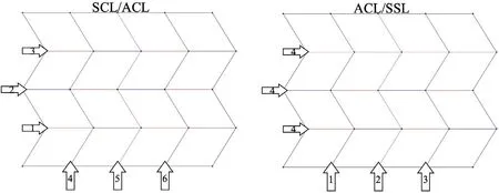
Fig.8. SCL/ACL and ACL/SSL folding orders.
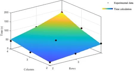
Fig.9. SCL/ACL folding order calculation and experimental data.
The ACL/SSL folding order presented a unique challenge to our framework,initially.Both of the SSL orders began simply as reversals of the straight-line/angled-line orders;but we found that once all of the angled lines were complete,the straight folds would naturally form when the structure was compressed from the edges.This prompted the implementation of a simultaneous fold contingency in the complexity calculation.This was accomplished with a simple logic statement regarding user input information:If a given folding order has an associated simultaneous fold (the number of which would be greater than zero),then all folds in the folding order after the simultaneous fold number will have their complexity reduced to zero.This treats the simultaneous fold as the final fold and removes the complexities of the remaining folds in the order.Previously,the framework overestimated the amount of time required to complete those patterns.Figure 10 shows that,with this modification,the framework predicts the completion times for the pattern with an error consistent with other folding orders.
Origami engineering has realized many unique applications that were previously infeasible.Advances in origami engineering have created more and more complex designs without considering the practical complexity of fabricating those designs.This paper pre sented a quantitative framework for calculating the complexity of origami manufacture based on the initial geometry and dynamic geometry during folding.The accuracy and versatility of the frame work in our study demonstrated that the underlying analytical methods are sound and that exceptional circumstances can be eas ily identified and changes easily implemented to account for them.From the qualitative analyses of the ergonomists in the literature review to the consistently accurate time calculations of our exper iments,the successful methodology we have developed and pre sented throughout this paper creates an open infrastructure which facilitates improvement as the field of origami engineering progresses.This framework is an early step in streamlining the design and assembly process for origami-inspired structures.Further experimentation in a diversity of scenarios will yield a wider applicability of the methodology and a greater understanding of human factors in origami engineering.The future of our research will explore how changes in pattern design,folding orders,and materials affect the complexity of origami structures.We will also investigate the influences of operator experience on speed and accuracy,by studying the learning curves of human operators and the machine learning capabilities of robotic operators and self-deployed systems.The applications of this research will improve the training of human and machine operators who may need to assemble origami structures far from the aid of experts.
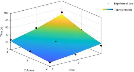
Fig.10. ACL/SSL folding order calculation and experimental data.
DeclarationofCompetingInterest
The authors declare no conflict of interest.
Acknowledgments
S.S.and X.N.acknowledge the financial support from the Pennsylvania State University startup funds.X.N.acknowledges the Haythornthwaite Foundation Research Initiation Grant from Haythornthwaite Foundation and Applied Mechanics Division of the American Society of Mechanical Engineers and the support from the National Science Foundation of US (Award number 2030579).
AppendixA.Samplefoldingorders
杂志排行
Theoretical & Applied Mechanics Letters的其它文章
- Why neural networks apply to scientific computing?
- Analytical solutions for inflation of pre-stretched elastomeric circular membranes under uniform pressure
- Computing mean fields with known Reynolds stresses at steady state
- Fundamental kinematics laws of interstitial fluid flows on vascular walls
- Analytical and numerical studies for seiches in a closed basin with various geometric shapes of longitudinal section
- Effect of interfacial stiffness on the stretchability of metal/elastomer bilayers under in-plane biaxial tension
