Study on the Performance of Micro-perforated Plate Absorber under Coupling
2021-07-03,
,
(1.School of Civil Engineering and Transportation,South China University of Technology,Guangzhou 510641,China;2.School of Naval Architectureand Ocean Engineering,Guangzhou Maritime University,Guangzhou 510725,China)
Abstract:A plate-cavity coupling model was proposed to calculate the acoustic attenuation performance of a micro-perforated plate on the cavity.The micro-perforated plate is generally a relatively thin plate,when the area of the plate is large,the vibration of the plate itself may also affect the sound field of the cavity.The model considers the influence of the micro-perforated plate and can more accurately calculate the noise reduction performance of the acoustic absorber of the micro-perforated plate.The noise reduction performance of the micro-perforated plate was evaluated using the Noise Reduction(NR).The experimental results show that the coupling model is accurate and reliable.Based on the proposed calculation model,the perforation rate,the back cavity thickness,the aperture and the plate thickness of the micro-perforated plate were optimized.
Key words:micro-perforated panel;coupling model;sound insulation
0 Introduction
The Micro-Perforated Plate(MPP)sound absorber has been widely researched and used due to its simple structure,environmental friendliness and fiberless material.[1-4].The basic theory of MPP was originally proposed by a Chinese scholar,Maa[5].The mechanism and design method of MPP sound absorption were discussed in detail[6].Most researches on MPP were based on the theory of Maa.In this theory,it is assumed that the MPPis rigid,ignoring the influence of the vibration of the plate.When the thickness or the rigidity of the plate is relatively large,the MPPcan be regarded as a rigid plate and the sound absorption performance can be calculated accurately;but if the plate is relatively thin,it is found that,in many experiments,its own mode has a strong influence on the acoustic performance,and that the influence of the plate vibration should not be ignored[7-10].Most of the existing works and calculations on MPPconsider MPPas an infinite rigid plate.At the same time,the back cavity is also considered as an infinite cavity.In engineering practice,the back cavity cannot be infinite.Therefore,the research of the micro-perforated plate under the coupling of the muffling performance can make better use of the micro-perforated plate.In past studies,the sound absorption coefficient of MPPat normal incidence was used as the only parameter for MPP,ignoring the performance of MPP absorbers when coupled with cavities[11].In an indoor sound field,the sound source will be coupled with the cavity,and the cavity bodies before and after the MPPwill be coupled together.Therefore,the actual noise reduction performance will be different from the sound absorption coefficient under normal incidence.
In this paper,the sound absorption performance of the MPPabsorber is related to consideration of the plate-cavity coupling.Firstly,the coupled model of the MPP sound absorber was obtained.Based on the proposed model,the experimental verification was carried out and the correctness of the coupled model was proved.Based on the proposed coupling model,the parameters of the MPP were studied,and the MPPabsorber wasoptimized.
1 Theory
1.1 Formula derivation
Fig.1 shows the system under investigation.A room is silenced using a micro-perforated sound absorber.The chamber is Cavity I.The back cavity of the micro-perforated plate is Cavity II,and the two cavities are separated by a micro-perforated plate.The coordinate system is established for the model.As shown in Fig.1,the micro-perforated plate is parallel to thexyplane,and the position on thezaxis isz1.The equation for the two cavities and micro-perforated plates is asfollows:

Fig.1 Diagram of MPPabsorber structure
For the Cavity I,

For the MPP,

For the Cavity II,

whereD=h3E/12(1-μ2)denotes the flexural rigidity of the plate;hdenotes the thickness of the panel;Eis Young’s modulus;μis Poisson’s ratio;mdenotes the area density of the MPP,which is the product of the densityρof the MPPand the plate thicknessh;qdenotes the point source amplitude;δ(x-x0)denotes the Dirac delta function;cdenotes the speed of sound;ρ0denotes the air density;pandware the sound pressure of the cavity and the normal vibration displacement of the MPP;vdenotes normal vibration velocity of MPP.The normal vibration velocity of the MPP consists of two parts,one part is the vibration of the MPPitself determined by the solid plate,and the other part is the vibration velocity of the air in the micro pores on the MPP,which is related to the pressure difference between the two cavities.It is assumed that the distance between the MPPholes is significantly smaller than the acoustic wavelength(a distributed array of holes across the MPP),and the particle velocity at the MPPsurface is modified by the fluid flow velocityvhthrough the holes.The net particle velocityvMPPformed by a combination of the normal velocity of the MPPv~MPPand the fluid motion velocityvhis expressed as follows[12]:

whereσdenotes the perforation ratio such as the fraction of open area holes.The particle velocityvhis represented in terms of the pressure difference of the cavities at its position and acoustic impedanceZMPPas follows:

The acoustic impedance of the MPPZMPPof a circular hole with a diameter ofdand a length ofth,such as the thickness of the MPP,are both low when compared to the acoustic wavelength given by Maa as follows[5]:

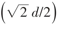

whereτ=η/ρ0is the kinematic viscosity.The displacement of the panels is expanded in terms of the structural modal shapeφnasfollows:

whereWndenotesthe amplitude of the modal displacement response.
The pressure in the cavities is expanded in terms of the acoustic modal shapeψnas follows:

wherePndenotesthe amplitude of the modal pressure response.
The structural modal shapes satisfy the following characteristic equation:

The acoustic modal shapessatisfy the following characteristic equation:

where the superscript‘cavity’represents Cavity I and Cavity II.In Eqs.(10)and(11),ωndenotes thenth structural or acoustic natural angular frequency.We substitute Eqs.(8)-(11)into Eqs.(1)-(3)and apply the orthogonality propertiesof modal shapesto obtain the following equations:
For Cavity I,

For the MPP,

For Cavity II,

where
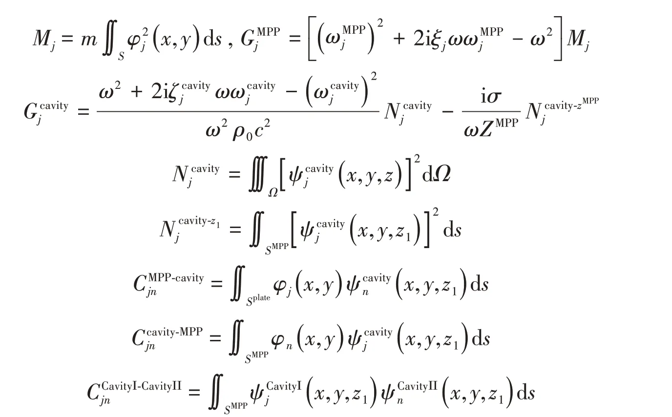
In the above equations,Qdenotes the modal amplitude of the sound source,ξjdenotes the modal damping ratio of thejth mode,ζjdenotes thejth modal factor of the cavity,andMjdenotes thejth modal mass of the panels.Additionally,Cjndenotes the modal coupling coefficient that characterizes the coupling strength between thejth structural or acoustic mode and thenth acoustic mode.Eqs.(12)-(14)constitute a system of linear equations that consist of a series of equations with five subsystems including MPP and two air cavities.The modality of each subsystem is truncated,and the number of truncations is represented byTx,wherexis a specific value,and they are combined into a linear equation group asfollows:

where

Eq.(15)constructs a set of linear equations with modal pressure of cavities and modal displacement of panels as unknowns.The equation is solved,and the pressure response inside the cavities and the normal vibration displacement of the coupled panels are obtained.
1.2 Calculation of noise reduction
The coupled algebraic Eq.(15)is solved by using MATLAB software.The solution provides all unknown modal amplitudes for the MPPand cavities.They are used to calculate the noise reduction(LNR).The acoustic energy in Cavity IisΠ,which is defined as:

whereVis the volume of the Cavity I.If there is no MPPabsorber for the noise control of the Cavity II,the governing equation is written as:

Using the modal expansion method,we obtain the modal sound pressure of the cavity without the control of the MPPsound absorber:

In this paper,all cavities are parallelepipeds,the modal can be expanded to the product of the cosine function:

wherean,bnanddnare the sub-modal orders of the cavity in thex,yandzdirections respectively in thenth cavity mode.The integral in Eq.(18)can be expressed as:

whereLx,LyandLzare the length,width and height dimensions of the Cavity I respectively.εa,εbandεdare calculated using the following formulas:

Substituting Eq.(20)into Eq.(18),we obtain the sound pressure amplitudes of the various modes of Cavity I,and then performing linear superposition to obtain the sound pressure of the cavity:

TheLNRof the MPPabsorber is obtained as follows:

whereΠ0denotes the acoustic energy in Cavity I without MPP absorber,Πmdenotes the acoustic energy in Cavity I with MPPabsorber.Π0is calculated using Eq.(16)withpIcalculated by Eq.(22)andΠmis calculated using Eq.(16)withpIcalculated by Eq.(15).
2 Experimental validation
In the previous formula derivation,some necessary assumptions and simplifications were made for the plates and cavities,and the model proposed in the previous section should be verified.The experimental setup is shown in Fig.2.High-density boards with a thickness of up to 50 mm,a density of 900 kg/m3,an elastic modulus of approximately 500 MPa,and Poisson’s ratio of 0.25 are employed to create the rigid box by using epoxy resin.The dimensions of Cavity I are:length(x)×height(y)×depth(z)=0.6 m×0.8 m×1.0 m,and the dimensions of Cavity II are:length(x)×height(y)×depth(z)=0.6 m×0.8 m×0.2 m.Fig.2 shows the working condition when Cavity I is connected to Cavity II.The two cavities are separated by microperforated plates.The size of the MPPis:length(x)×height(y)=0.6 m×0.8 m,thickness 0.3 mm,perforation rate 1.5%,and small hole diameter 0.19 mm.A plurality of microphones is placed in the cavity to test the sound pressure at different points,and the measured sound pressure will be used to determine the acoustic energy in Cavity I.A square hole measuring 0.1 m×0.1 m is located at the top of the cavity.The center of the square hole is[0.2,0.8,0.85]in meters,and a 6.5-inch speaker is mounted on it as a sound source.A small cavity behind the speaker separates the speaker from the outside,so that the speaker produces only a forward plane wave.The actual excitation is a plane wave incident from the square hole into the cavity.Since the coupling between the plane wave and the cavity is complicated,in the numerical simulation calculation,the point sound source is used instead of the plane wave for excitation.Due to the difference between the experimental model and device,corrections are needed to ensure the accuracy of the calculation results.Cummings[13]gave a correction formula using point sources instead of square holes:


Fig.2 Experimental setup
wherercdenote the position vector of the point source;the value of the subscripti,which is equal to 1,2 and 3 respectively,represents values in thex,yandzdirections;ndenotes the order of the modes in the corresponding direction;εis the size of the opening in the corresponding direction;andlis the cavity size in the corresponding direction.After the correction of the formula,a point source can be used instead of a plane wave to stimulate the air in the box.In the experimental setup,the boundary conditions of the MPPwas fixed.In the calculation,the method proposed by Xin et al[14]was used to expanding modal of the fixed plate.
Fig.3 compares the measuredLNRwith those obtained from the simulations.It can be seen from the figure that the experimental results have six large absorption peaks with a peak value of about 40 dB below 600 Hz,and that the calculated values are well estimated for these six peaks.At higher frequencies,the absorption peaks are more difficult to distinguish,and the experimental data are consistent with the simulation results.The sound absorption coefficient of the MPP absorber obtained according to the Maa’s theory is also shown in Fig.3,where the MPPis assumed to be rigid.According to Maa’s theory,the MPPabsorber has two absorption peaks in the frequency range,the first one is about 350 Hz,the other is about 1 000 Hz,and the peaks are close to 1,which is completely absorbed.Maa’s theory only considers the coupling between the MPP and the back cavity,and does not take into account the coupling between the front large cavity and the MPPsound absorber.Therefore,there are big differences in the calculated absorption curve and the actual noise reduction.It can be seen from the figure that the MPPsound absorber has a plurality of narrow absorption peaks.It can be seen that the vibration of the MPPitself has a great influence on the sound field outside the MPPsound absorber.At the same time,the boundary conditions of the finite back cavity also affect the performance of the MPPsound absorber.Comparing the noise reductionLNRand the sound absorption coefficient of the experimental test,it can be found that only the sound absorption coefficient is used as the sound absorption performance of the MPP,and it is difficult to accurately describe the absorption sound characteristics of the MPPin actual use.

Fig.3 Noise reduction comparison between experimental and calculation results
In Fig.4,the spectrum in Fig.3 is converted to one-third octave,and thus it is easier to compare calculation results and experimental test results.As can be seen from Fig.4,at all frequencies,the difference between the two is no more than 3 dB,so it can be considered that the results of the model calculation are accurate.At the center frequency of 400 Hz,the experimental results and the noise reduction values of the calculated results are substantially equal,while at other frequencies,the model calculation results are slightly larger than the experimental test values.Because the experimental conditions are not completely ideal,for example,the size of the experimental box is not accurate enough,the manufacturing error of the micro-perforated plate causes inaccurate parameters,and the influence of the box itself,the noise reduction value tested is slightly less than that of the calculation value.However,this difference is only within the calculated error range,and it can be seen that the calculation model hasa quite good accuracy.

Fig.4 Noise reduction comparison between experimental and calculation results in 1/3 octave
The stability and accuracy of the coupled model calculations presented in Chapter 1 of this paper are verified by comparison of calculations and experiments.Next,the relevant parameters of the micro-perforated plate will be optimized to find the relationship between the sound absorption characteristics of the micro-perforated plate and related parameters,so as to facilitate the desired performance by adjusting the parametersin practical applications.
3 Parameter optimization of MPPabsorber under coupling
The main influence parameters of the single-layer MPP absorber are the back-cavity depth,the perforation rate,the small hole diameter and the thickness of the MPP.The optimization of these four parameters of the MPPwill be carried out below.According to the model established in Chapter 1,Cavity I is set to be the main cavity size:length(x)×height(y)×depth(z)=0.6 m×0.8 m×1.0 m,and the size of the MPPis 0.6 m×0.8 m.These parametersare constant in later optimization studies.For the convenience of calculation,the boundary conditions of the MPP are all set to simple support.The modal expansion of the simple support isas follows:

whereaandbare the numbers of modes in thex-direction and they-direction of the plate in thenth-order plate mode respectively.Using the modal expansion to calculate the simply supported MPP can greatly improve the calculation speed of the coupled model and save computational resources.
3.1 Influence of back cavity depth
This section studies the effect of the depth of the back cavity of the MPPon the noise cancellation performance.The perforation rate of the MPP was set to 1.5%,the aperture of the small hole was 0.19 mm,and the thickness of the MPPwas 0.3 mm.The thickness of Cavity II was changed to calculate and compare,and the NR pattern of the MPP absorber was obtained with different back cavity depths.
Fig.5 shows the comparison of the noise reduction with the depth of the back cavity from 6 cm to 28 cm.It can be seen from the figure that as the depth of the back cavity increases,the peak of the MPPsound absorber rises at the first absorption peak,while the higher frequency peaks remain substantially unchanged.As the first resonance absorption peak continues to increase,a decreasing sound absorption valley occurs before the resonance absorption peak.This valley value even reaches-30 dB when the back-cavity depth reaches the maximum of 28 cm.The peak frequency of the first absorption peak is about 180 Hz,and the valley value is about 160 Hz.Since this valley is already negative,the noise is amplified at this frequency.To see the noise reduction performance in this band,it can be viewed by a one-third octave.Fig.6 shows the spectrum in Fig.5 to one-third octave.It can be seen that in the frequency band with a center frequency of 160 Hz,the noise reduction value still increases with the increase of the back-cavity depth.Although the large back cavity depth will have a reverse absorption peak before the first absorption peak,it does not affect the sound absorption performance of the MPP absorber in the low frequency(160 Hz)band.In the study of the infinity and the assumption that the MPPis rigid,the depth of the back cavity does not change the maximum sound absorption coefficient and the sound absorption bandwidth of the MPP,and only the sound absorption peak is shifted to the low frequency;in the calculation of the coupled model,it can beseen that theincreasein thedepth of theback cavity only increasesthemufflingperformance of the MPPsound absorber at the first resonance absorption peak of the low frequency,and doesnot causeasignificantdecreasein themufflingperformanceat thehigh frequency.
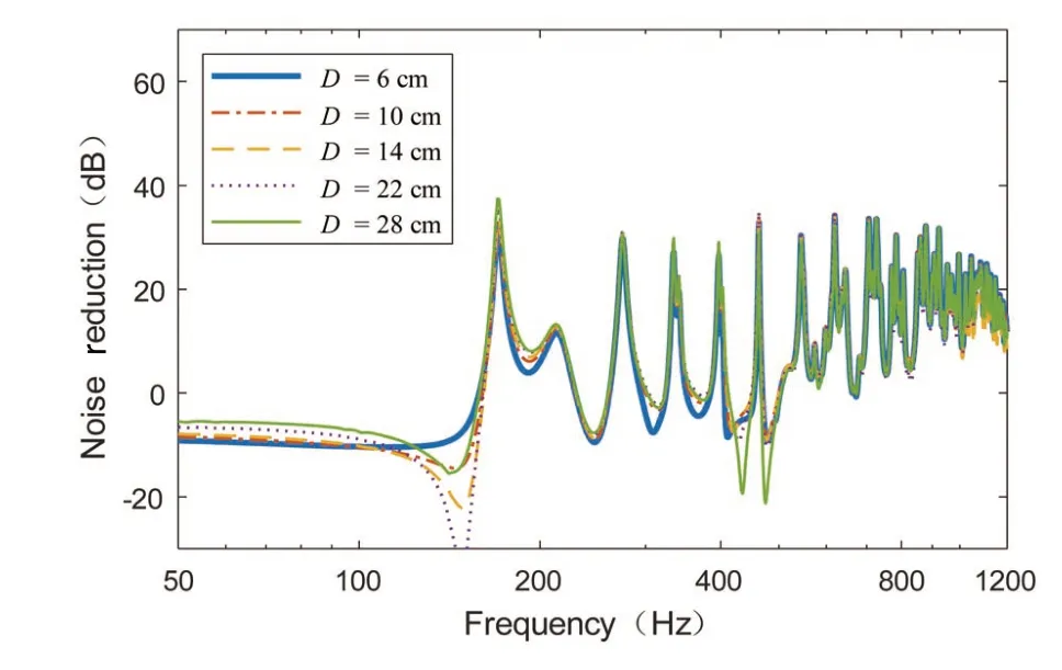
Fig.5 Noise reduction comparison at different back cavity depths

Fig.6 Noise reduction comparison at different back cavity depths in 1/3 octave
3.2 Influence of perforation ratio
This section studies the effect of the perforation rate of MPPon the performance of noise reduction.The micro-perforated plate has a back-cavity depth of 0.2 m,a small hole diameter of 0.19 mm and a plate thickness of 0.3 mm.Only the perforation rate of the micro-perforated plate is changed for calculation and comparison,and the muffling performance curve at different perforation ratesisobtained.
Fig.7 shows the muffling performance of the MPPsound absorber at different perforation rates,and Fig.8 converts the spectrogram shown in Fig.7 to one-third octave.As can be seen from the figure,as the perforation rate increases,the noise consumption of the MPPincreases at almost all frequencies.When the perforation rate is relatively small,increasing the perforation rate can greatly improve the noise reduction performance of the MPPsound absorber;when the perforation rate increases to a certain value,the perforation rate of the MPPfurther increases,and the noise is slowly reduced.Performance is also increasing,but not as much as the perforation rate.As seen from Fig.8,when the perforation rate isincreased from 0.2%to 1.8%and from 1.8%to 5.8%,the perforation rate is increased by 1.6%and 4%respectively,while the noise reduction amount is greatly increased,and the increase is the maximum,which improves nearly 20 dB.When the perforation rate is above 5.8%,the increase in noise reduction becomes very slow,increasing from 5.8%to 9.8%,the perforation rate is increased by 4%,and the maximum increase in noise reduction is only about 5 dB.In the study of the infinity and the assumption that the MPPis rigid,the increase of the perforation rate of the MPPwill broaden the bandwidth of the sound absorption and affect the maximum sound absorption coefficient,and there is an optimal perforation rate value.At the perforation rate,the maximum sound absorption coefficient of the MPPsound absorber can reach to 1[15].In the calculation of the fully coupled finite-size micro-perforated plate absorber,we can see that the performance of noise reduction has been increasing with the increase of the perforation rate.In the case where the pore diameter of the MPPis constant,increasing the perforation rate of the MPPis equivalent to increasing the number of small holes of the MPP.The sound energy is consumed through the small hole and inside the back cavity.Incresing the number of small holes can make it easier for sound waves to enter the back cavity,dissipating sound energy in the back cavity.The consumption will be more.So increasing the perforation rate of the MPPcan greatly increase the muffling performance of the MPP.When the perforation rate becomes larger and larger,although more sound waves enter the back cavity,the coupling of the two cavities through the small holes is stronger,so the noise reduction is smaller.If the perforation rate is increased,the coupling between the two cavities is also stronger and will drop rapidly after reaching a certain value.When the perforation rate is 100%,that is,when there is no micro-perforated plate,there is no noise reduction effect,that is,LNR=0.It can be concluded that when the micro-perforated plate is used to eliminate noise in the closed cavity,the perforation rate of the micro-perforated plate can be appropriately increased to obtain a better muffling performance.

Fig.7 Comparison of noise reduction when MPPuses different perforation rates

Fig.8 Comparison of noise reduction when MPPuses different perforation rates in 1/3 octave
3.3 Influence of hole diameter
This section discusses the effect of the diameter of the small holes on the MPPsound insulation performance.The MPPwas set to have a perforation rate of 3%,a plate thickness of 0.3 mm and a back-cavity depth of 0.2 m.The calculation results of different aperture sizes are compared,and the noise reduction curves at different apertures are obtained.
Fig.9 shows the muffling performance of MPP sound absorber with different perforation rates,and Fig.10 converts the spectrogram shown in Fig.9 to a one-third octave.As can be seen from Fig.9,when the size of the aperture is increased,the performance of the MPPsound absorber is first increased and then decreased.In the first-order resonance absorption peak of the MPP sound absorber,the pore diameter of the micro-perforated plate reaches the highest at 0.75 mm,and then decreases slightly,and the extent of the decrease is not large,and is basically about several decibels.At higher frequencies,the noise reduction value of the MPPis maximized at 0.25 mm and then rapidly decreases.It can be more clearly seen from Fig.10 that the noise reduction performance of the MPPsound absorber among the aperturesisdifferent.Comparing the noise reduction at a hole diameter of 0.25 mm and 0.05 mm,the maximum difference is nearly 30 dB.According to the results of the infinitely large rigid MPP,the aperture has an optimum value so that the maximum sound absorption coefficient is equal to 1,and increasing or decreasing the aperture reduces the maximum sound absorption coefficient of the MPP,except that the aperture is reduced.The sound absorption bandwidth becomes larger,and the sound absorption bandwidth becomes narrower when the aperture is increased.This conclusion is basically supported when comparing the sound absorption model of a finite-size flexible board to a rigid board.When the aperture is very small and becomes ultra-microporous,the amount of noise reduction in the entire frequency band is very low,which is actually a low absorption with little significance,so in the design of the MPPsound absorber,the aperture of the MPPshould be set very low.As seen from Fig.10,the optimum aperture is 0.75 mm at frequencies below 250 Hz;the optimum aperture is 0.25 mm at frequencies of 315 Hz and above.In the actual structural design,it is necessary to make certain trade-off.A slightly smaller aperture can obtain better sound-absorbing performance at high frequencies,and if the noise at low frequencies is mainly reduced,the aperture of the micro-perforated plate needs to be appropriately enlarged.
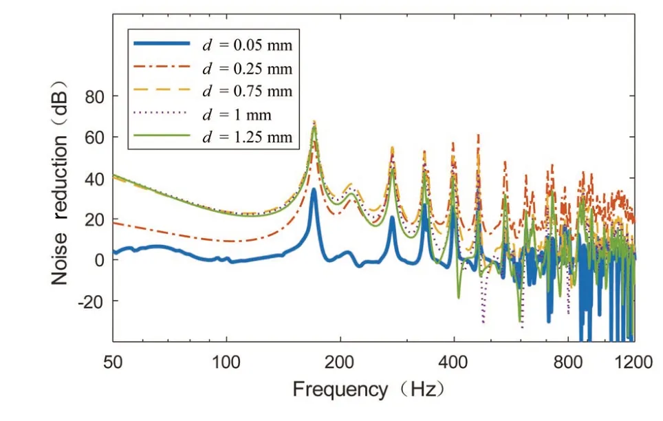
Fig.9 Comparison of noise reduction in MPP with different hole diameters
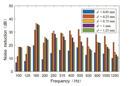
Fig.10 Comparison of noise reduction in MPPwith different hole diameters in 1/3 octave
3.4 Influence of MPPthickness
This section discusses the effect of the thickness of the MPPon the sound absorbing performace.The depth of the back cavity of the micro-perforated plate was set to 0.2 m,the perforation rate was 3%,and the diameter of the small hole was 0.8 mm.The thickness of the micro-perforated plate was changed to calculate and compare,and the noise reduction curve of different micro-perforated plate thickness was obtained.
Fig.11 shows the muffling performance of the MPPsound absorber at different plate thicknesses,and Fig.12 converts the spectrogram shown in Fig.11 into one-third octave.As can be seen from the figure,the increase in the thickness of the MPPreduces the noise reduction performance of the MPP sound absorber.For MPP,the plate thickness is the length of the micro pores.Changing the plate thickness of the MPP changes the slenderness ratio of the micro pores,which influences the performance of the entire sound insulation system.As seen from Fig.12,except for the center frequency of 630 Hz,the amount of noise reduction is substantially unchanged when the plate thickness is changed.At other frequencies,the amount of noise reduction substantially decreases as the thickness of the MPPincreases.The sound absorption bandwidth of an infinitely large micro-perforated plate decreases as the thickness of the plate increases,and an optimum MPP thickness can maximize the sound absorption coefficient.Comparing the limited-size flexible MPP used in this paper,the performance of noise reduction decreases with the increase of the thickness of the sheet,indicating that the thickness of the thin micro-perforated sheet can achieve a better sound-absorbing effect.When the thickness of the MPPis increased,the distance between the two chambers of the room and the back cavity is actually increased.In the case where the perforation rate and the aperture of the MPPare constant,this reduces the exchange of acoustic energy between the two cavities,that is,the consumption of acoustic energy on the MPP is reduced,and therefore,the MPP should choose a smaller thickness for better noise reduction.When the thickness of the MPPis very small,the plate actually becomes a film,and the MPPmuffling structure becomes a film sound absorbing structure with a hole.The thin film sound absorbing structure is characterized by the use of a small back cavity to produce a resonant absorption peak up to 1 at a very low frequency[16-17].It can also be seen from Fig.12 that when the plate thickness of the MPPbecomes small,the noise reduction of the MPPsound absorber at low frequencies is obviously greater than that of the medium and high frequency,and also hassome characteristics of a filmsound absorbing structure.

Fig.11 Comparison of noise reduction of different MPPthickness
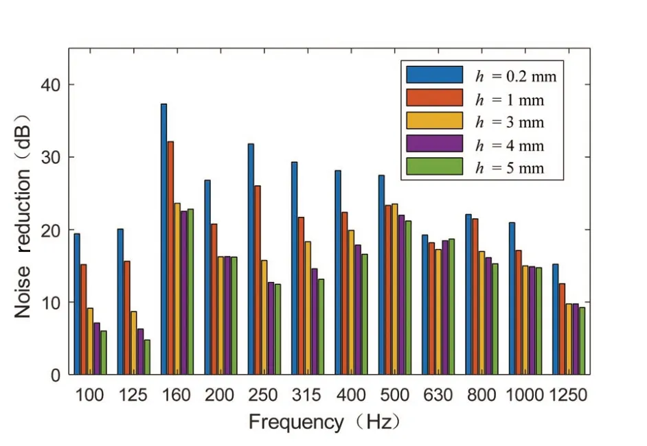
Fig.12 Comparison of noise reduction of different MPPthickness in 1/3 octave
4 Conclusions
In this paper,the noise reduction performance of a finite-size micro-perforated plate sound absorbing structure under plate-cavity coupling is studied.A coupling model suitable for the structure is proposed,and the calculation method of acoustic propagation loss of the structure is obtained.The validity and reliability of the coupled calculation model are verified by experiments.The coupled model can reliably predict the noise reduction of the room using the MPP sound absorber.The calculation results show that the boundary conditions have effect on the performance of the MPPsound absorber.Only the sound absorption coefficient is used as the sound absorption performance of the MPP,and it is difficult to accurately describe the absorption sound characteristics of the MPPin actual use.Through the study of the MPPparameters,the following conclusions can be drawn:
(1)Increasing the depth of the MPPback cavity can increase the muffling performance of the MPPsound absorber at low frequencies,and the change at high frequency is not obvious.
(2)When the perforation rate of the MPPis very small,increasing the perforation rate can greatly increase the muffling performance of the MPPsound absorber.Therefore,in actual use,the perforation rate of the MPPcan be appropriately increased to obtain better sound-absorbing effect.
(3)A small aperture can obtain a better muffling performance at medium and high frequencies,and a slightly larger aperture performs better at low frequencies.
(4)The increase in the thickness of the MPP reduces the noise reduction performance of the MPPsound absorber.
杂志排行
船舶力学的其它文章
- Application of the Cell-vertex Finite Volume Method in the Solution of the Lubrication Characteristicsof Journal Bearings
- Numerical Simulations on the Dynamic Characteristicsof a Shallow-draft Spar-type Floating Wind Turbine
- Study on Torque Characteristics and Structural Strength of Large Container Shipsunder Oblique Waves
- Collapse Analysis of Model Sphere of Titanium Manned Cabin under External Pressure
- Numerical Investigation of Dynamic Responsesof Ship Structure and Gas Turbine Subjected to Underwater Explosion
- Experimental Study on Characteristicsof Marine Propeller Cavitation and Noise
