Numerical Investigation of Dynamic Responsesof Ship Structure and Gas Turbine Subjected to Underwater Explosion
2021-07-03,,,,
,,,,
(1.Tongji University,Shanghai200092,China;2.Harbin Marine Boiler&Turbine Research Institute,Harbin 150078,China;3.Huazhong Institute of Electro-Optics,Wuhan 430070,China;4.College of Shipbuilding Engineering,Harbin Engineering University,Harbin 150001,China)
Abstract:Dynamics responses of the ship structure and the gas turbine subjected to underwater explosion are investigated numerically in this paper.Firstly,the underwater explosion numerical model near free surface is established based on the Coupled Eulerian-Lagrangian method.Then,both the shock environment of the ship structure and the dynamics responses of the gas turbine subjected to different underwater explosion loads are simulated by incorporating with the hull-equipment integrative method.Finally,the influences of the underwater explosion condition parameters on the damage response characteristics are analyzed to offer technical reference for the anti-shock design of the gas turbine.
Key words:underwater explosion;gas turbine;dynamics responses;Coupled Eulerian-Lagrangian method;anti-shock
0 Introduction
Underwater non-contact explosion is one of the major threats to ship survivability.The shock wave load,bubble pulsation load as well as hysteresis flow load generated by underwater explosion will not cause the breakdown of the ship structure,but will cause large-scale damages to the naval equipment[1-2].Therefore,the shock resistance capacity of the shipboard equipment has always been a strong concern of navies.Besides,gas turbine engines play an important role in modern warship propulsion systems.Anti-shock performance of a gas turbine will directly affect the combat capability and athletic ability of the warship.
The research on underwater explosions can be traced back to the actual ship anti-explosion experiments[3]carried out in the last century.However,the responses of ship structures subjected to underwater explosion(UNDEX)is quite complex,involving Fluid-Structure Interaction(FSI),high strain rate constitution equations,material and geometric nonlinearities,tensile tearing,and rupture etc[4].Limited experimental data can be obtained from previous studies.Besides,due to the high cost of real ship experiment for its poor repeatability,the numerical method has become an effective alternative tool to study dynamic responses of hull structures and naval equipment.The difficulty in numerical analysis is how to simulate the load generated by UNDEX and fluid-structure interaction accurately.Shock wave and its damage to the structure have been studied for a long time.Double progressive approximation DAA method of underwater shock wave analysis program(De Runtz,1989)[5]proposed by Geers(1978)[6]is well-known.The bubble dynamics theory of underwater explosion proposed by Cole(1948)[3]has been in use ever since it was published.Geers and Hunter[7-8](GH)developed a procedure which can calculate the pressure generated by underwater explosion at any point in a flow field.But it does not consider geometric nonlinearities of bubbles as well as effect of hysteresis flow on hull structures.Dynamic design analysis method[9-10]has been widely used.But it is only applied to independent equipment.However,there is little research on the interaction between three-dimensional bubbles and hull structures as well as naval equipment.Besides,few discussions are related to a close-in non-contact UNDEX problem.Zhang et al[1]investigated dynamic response of the non-contact underwater explosions on naval equipment based on acousticstructure coupling method,by which the interaction between the ship’s wet surface and the surrounding flow field can be calculated.However,it does not take the non-linear coupling of shock wave load,bubble pulsation load,free surface and hysteresis flow into consideration.
In this paper,close-in non-contact underwater explosion numerical model near free surface is established based on the Coupled Eulerian-Lagrangian(CEL)method by considering the compressibility of the flow field and boundary nonlinearities.And the presented model is validated by comparing with the classical GH model and empirical formula.Then,the damages to the hull structure and shipboard equipment resulting from specific close-in non-contact UNDEX loads can be analyzed based on the integrated ship-equipment model.Finally,the dynamic response of gas turbine under a specific UNDEX condition is analyzed.
1 Theory and numerical methods
1.1 Brief theory of Coupled Eulerian-Lagrangian Method
In the Lagrangian method,the shape of a cell changes as the shape of the object changes,whose advantage is that the governing equation can be simplified,and the boundaries of objects can be accurately described.However,when considering large deformation problems such as UNDEX problem,the Lagrangian cell will be severely distorted,resulting in non-convergence of the calculation.The Eulerian method,also known as the space-point method,uses spatially consecutive regular cells,and the material can flow between the cells.So the Eulerian method can deal with large deformation problems,but it is difficult to capture material’sinterface.
Based on the above methods,Noh[11]firstly proposed a Coupled Eulerian-Lagrangian method,which combines the advantages of the two methods.Eulerian material can interact with Lagrangian elements through Eulerian-Lagrangian contact;simulations that include this type of contact are often referred to as Coupled Eulerian-Lagrangian analysis[12-15].This powerful,easy-to-use feature of general contact enables fully coupled multi-physics simulation such as fluid-structure interaction as well as UNDEX.
When dealing with structure response problems,the explicit finite element method is adopted,whose basic idea is that it introduces the polycondensation mass matrix based on the traditional Galerkin method in order to reduce the amount of computation for a single step.Besides,the second-order central difference formula is used for explicit integration at time step.The semi-discrete formof the governing equation[16]is

whereρis the mass density andfirepresents the components of the body force,ui()tis the prescribed displacement on part of boundary,Γu.girepresents the components of the tractions on part of the boundaryΓs.ΦNandΦMrepresent the shape function of finite element.The stressσijis a function of the deformation and material properties.
That is,at each time increment step,firstly,the physical quantity and the grids are updated according to Lagrangian method.
When dealing with fluids,the Eulerian method incorporating the operator splitting technique is used.That is,at each time increment step,firstly,the physical quantity and the grids are updated according to the Lagrangian method;Secondly,the Eulerian step is introduced to move girds back to its original position,and it considers the physical quantity advection between the new grid and the old grid,which uses the second order MUSCL[16]algorithm.
Based on underwater explosion analysis,there are water,air,explosives,and other materials in the Eulerian domain.In order to capture the material’s interface,Volume of Fluid Method(VOF)proposed by Hirt et al[17]isadopted in thispaper.
Through experimental analysis,the first bubble pulsation period and the maximum radius of the bubble generated by TNTcan be approximatly described by the following formulas[3,18]:

whereTis the bubble pulsation period(s),Rmis the maximum radius of the bubble(m),Wis the mass of the explosive(kg),andHis the depth of detonation point(m).
1.2 Validation of the numerical model
Firstly,the numerical model of underwater explosion is established in ABAQUS[12].150 kg of TNT with detonation point 10 m away from water surface is selected as the calculation condition.The equation of state(EOS)and the material constants used in this paper are shown in Tab.1.Fig.1 is a sketch of the computational domain.There are three kinds of materials in the calculation domain.Then,the air,water,and explosives are assigned to different areas in Euler domain using Volume of Fluid Method(VOF).According to the empirical formula,the bubble pulsation period is estimated to be 0.896 s and the maximum bubble radius is 6.616 m.Calculation time is set as 1.5 s.

Fig.1 Sketch of computational model

Tab.1 Material properties[12,19]
Setting pressure boundary conditions for surfaces of the model,and the upper and lower surfaces are completely fixed.Minimum grid size of the finite element model is 0.3 m and maximum grid size is 1 m.The total number of grids is 924 700.
Several major stages of underwater explosion are well simulated by using Coupled Eulerian-Lagrangian method:detonation of explosives,propagation of shock wave,bubble pulsation,and hysteresisflow,which are shown in Fig.2.

Fig.2 Main stages of underwater explosion
Explosive detonation process is completed within 10-5~10-2s[19],generating a high-temperature high-pressure air mass after detonation,the initial pressure is very large.Then,the water around the explosives is compressed suddenly,producing a shock wave in water at a speed of about 1 500 m/s[20],when shock wave propagates to free surface or the surface of solid,it will produce reflection.After that,due to the pressure inside the bubble is higher than the ambient pressure,the bubble begins to swell,with the volume increasing,pushing the surrounding water forward.Besides,the free surface of the water is raised.The pressure inside the bubble decreases to the ambient pressure due to expansion,but the bubble continues to swell due to inertia.Finally,the radius reaches the maximum.Currently,the pressure inside the bubble is lower than the ambient pressure.Then the bubble begins to shrink,the surrounding water begins to move backwards,compressing the bubble to the minimum,then,the pressure inside the bubble is higher than the ambient pressure,the bubble begins to swell again.Again and again,the process is called bubble pulsation.After pulsations for several times,the bubble eventually collapsesand producesa high-speed jet.
It can be seen from Fig.3 that the maximum radius of the bubble is 5.776 m at 0.37 s,and the minimum at 0.76 s.Then followed by the second bubble pulsation,the bubble collapses at 1.5 s,producing a high-speed jet upward under gravity.
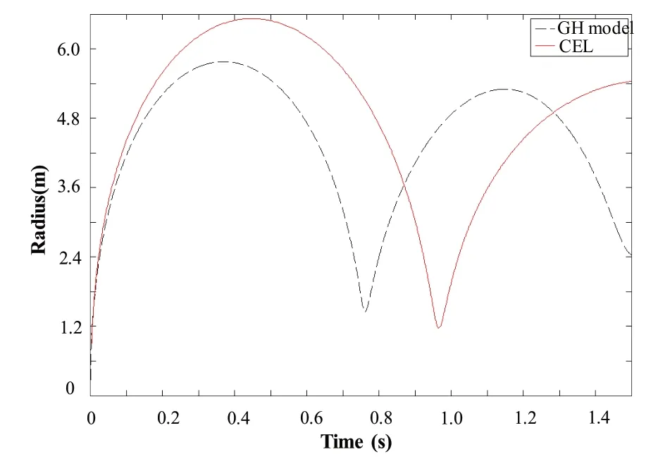
Fig.3 Comparison between the bubble radius curves with different methods
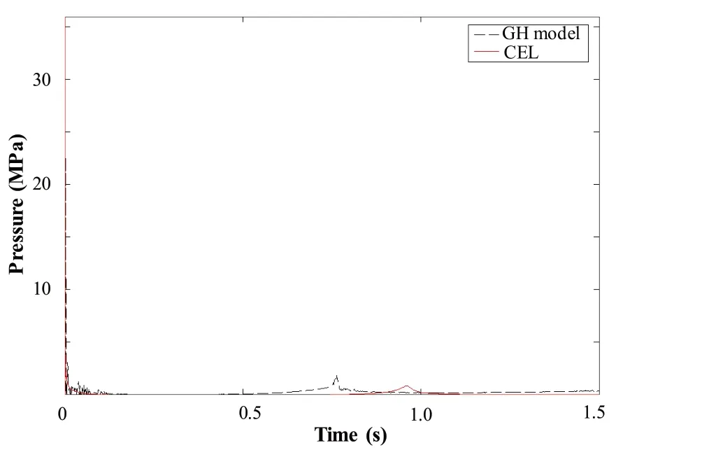
Fig.4 Comparison between the pressure curve with different methods
And then,measuring point at a distance of 1.5Rmaxaway from the detonation point is selected.Pressure curve of the flow field in Coupled Eulerian-Lagrangian model is plotted.Comparing with the curve drawn by GH pressure model[7],both are shown in Fig.4.Bubble radius curve of GH model isshown in Fig.3.

Tab.2 Bubble pulsation period and maximum radius with different models
As shown in Tab.2,the empirical formula is obtained by deep-water bubble experiments,which can only be used as a preliminary estimation formula,when the condition changes,for example,an underwater explosion near the free surface,the dynamic characteristics of the bubble will differ greatly fromthe empirical formula.
In GH model,only spherical bubble in the non-gravity field is considered.Nonlinear interaction between bubble and free surface,non-spherical effect of bubble and the effect of atmospheric pressure are not considered.In fact,the movement of bubble in flow field shows non-spherical features,and it is affected by free surface and atmospheric pressure.Therefore,the maximum radius and pulsation period of the bubble in the CEL model are smaller than those of the GH model.Due to the grid size,the pressure peak is slightly smaller than that of the GH model.The pressure eventually tends to zero in GH model,but tends to ambient pressure in CEL model.The small oscillations are due to the reflection of the shock wave at the free surface and the numerical oscillations.However,the trend is basically the same in the two models,the total momentum is equivalent.So the impact on the structure will not differ greatly.
Through the calculation results,it can be found that the model with Coupled Eulerian-Lagrangian Method can capture the main features of all stages of underwater explosion well.Besides,the simulated environment is closer to the actual working conditions,which proves that the model is effective in calculating underwater explosion loads.
1.3 Simulation method of hull-gas turbine integration
At present,the Dynamic Design Analysis Method(DDAM)[10]is widely used in the shock resistance research of the naval equipment.Although it has a better efficiency when the modal information of the structure is known,the applications are limited due to the linearized assumptions.Firstly,only the equipment with linear installation can be analyzed.Secondly,only the linear elastic response can be analyzed.Thirdly,it dose not consider the coupling effect of nearby equipment and the hull structure.
On this basis,we adopt the theory for coupled vibrations of master-salve systems,that is,the integrated ship-equipment model.Firstly,the interaction properties between the equipment and the hull are defined.Then,the quality,stiffness and damping coefficient of the damper are simulated.Lastly,shock response to gas turbine and hull structure under different underwater explosion conditionsin time domain is analysed.
2 Analysis of computing results
2.1 Numerical model setup
In this paper,a single cabin is extracted from a surface ship whose draft is 4.5 m.Two gas turbines are symmetrically placed on the inner bottom.An explosive charge of 150 kg TNT is placed at a depth of 10 m and right below the cabin’s center such that the standoff distance from the cabin bottom is 5.5 m.The configuration of thisproblem isshown in Fig.5.
Modeling and meshing are completed in Hypermesh,the structure of simplified gas turbine model and cabin model are shown in Figs.6-7.

Fig.5 Layout diagramof cabin and explosive
The spring-damping element is adopted to simulate the vibration isolator fixed between the gas turbine and the ship hull.And,the spring mechanical parameters are shown in Tab.3.The gas turbine discussed in this paper,a total of 32 vibration isolators are installed under itsbase.

Fig.6 Simplified finite element model of gas turbine
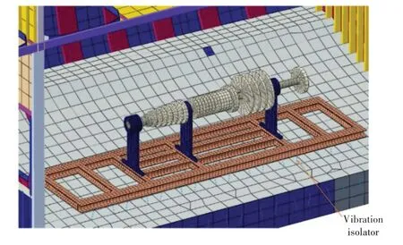
Fig.7 Assembly of gas turbines-hulls

Fig.8 Whole computational domain

Tab.3 Spring mechanical parameters
The CEL finite element model in ABAQUSis established,material properties,solvers and other parameters are defined.Meanwhile,the hull-gas turbine finite element model is imported into ABAQUS,and the interaction properties between hull and gas turbine,hull and flow field are defined.The computational domain isshown in Fig.8 after defining all properties.
2.2 Coupling processbetween underwater explosion and hull structure
As shown in Fig.9,the shock wave firstly comes into contact with the hull at 7.5 ms,causing dynamic response on it.Mises stress at the bottom of the hull suddenly increases.Then,it propagates upwards from the bottom in the form of stress wave,which gradually decays in propagation.As can be seen in contours,the pressure of the hull structure near the detonation point is obviously higher than the farther one.Then,the bubble begins to expand,the hull is raised,resulting in slight hogging at 0.15 s.The shock wave generated by bubble pulsation also causes dynamic response on the structure.Finally,the bubble collapses,resulting in high-speed jet that causes a huge impact on the hull bottom at 1.5 s.

Fig.9 Interaction between underwater explosion loads and the hull
2.3 Dynamic response of gas turbine
The dynamic response of a gas turbine largely depends on that of the equipment base mounted on the hull,so,the dynamic response of the equipment base should be analyzed first.In this case,we select some typical nodes on the equipment base,then,draw velocity-time response curve and displacement-time response curve.Fig.10 shows the velocity-time response curve of the equipment base while Fig.11 displaysthe displacement-time response curve of the equipment base.
It can be seen from Fig.10 that the high frequency response appears in the first 0.1 s,which is induced by the impact of the shock wave on the hull,and that the low-frequency part shows after 0.6 s because bubble encounters the hull.When the bubble collapses at about 1.5 s,the response velocity peaks around 1.8 m/s,which is only 25%of the first peak velocity caused by shock wave.As shown in Fig.11,the displacement response of the gas turbine base is caused by the long-time bubble pulsation pressure.When the bubble collapses,there is another peak at about 1.4 sas well.
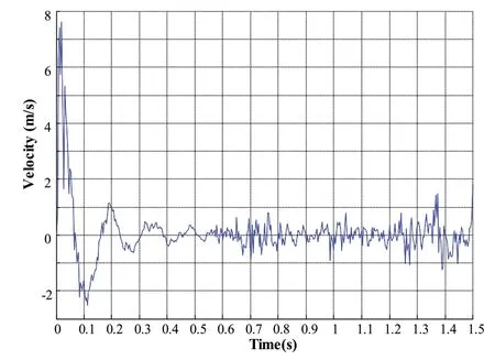
Fig.10 Velocity-time response curve of gas turbine base

Fig.11 Displacement-time response curve of gas turbine base
To further explain this phenomenon,the response curve of node velocity for typical parts of the gas turbine is shown in Fig.12,corresponding with the velocity,and the curve of the displacement of the equipment relative to the hull bottomisshown in Fig.13.
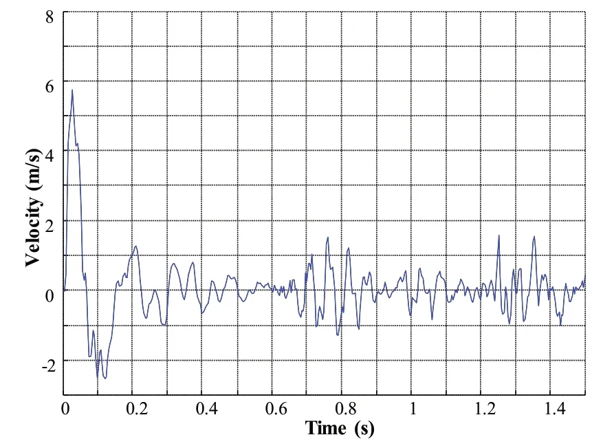
Fig.12 Response curve of node velocity for typical parts.

Fig.13 Displacement curve of gas turbine relative to hull bottom
It can be seen from Fig.12 that beforet=0.6 s,the velocity of the gas turbine increases rapidly resulting from the impact of shock wave and decays gradually with the same trend as the base shown in Fig.10.When the bubble encounters the hull aftert=0.6 s,there are multiple peaks as well.When the bubble collapses,the maximum value of the node velocity of the gas turbine is about 1.6 m/sat 1.35 s.
As shown in Fig.13,the node displacement of the gas turbine relative to the hull bottom manifests the vibration of the equipment after being shocked.Because the gas turbine is connected to the hull base by the vibration isolator.The vibration isolator of gas turbine is compressed with the hull at the shock wave stage,and the vibration amplitude of the gas turbine is relatively large in the first tension with a maximum value of 55 mm.Then it gradually decays before the bubble encounters the hull att=0.6 s,it increases again under the action of bubble pulsation load.And the amplitude value tendsto continue to increase after the bubble collapses,the peak value is38 mm.
In order to check the safety of the gas turbine and its base,the stress and strain response of the gas turbine under the UNDEX loads are analyzed.Fig.14 shows the Mises stress on the simplified gas turbine model at different moments.Besides,Fig.15 shows the PEEQon the simplified gas turbine model at different moments.At 7.5 ms,the shock wave load plays a major role,the Mises stress of the gas turbine is rapidly increasing,besides,there is an obvious stress concentration phenomenon on the base.During the bubble pulsation period,the peak value of Mises stress is obviously reduced.But the whip motion caused by bubble pulsation results in deformation of the gas turbine structure.At 1.5 s,the bubble collapses,and produces a high-speed jet,resulting in severe deformation of the local structure on the base.

Fig.14 Mises stress on the simplified gas turbine model at different moments
It can be seen from Fig.14 that the maximum Mises stress of structure under shock wave load is larger than the maximum Mises stress under bubble pulsation load.At 0.007 5 s,i.e.during shock wave period,the maximum stress reaches about 510 MPa while the maximum stress during bubble pulsation reaches about 350 MPa.The stress response of the gas turbine increases rapidly and the peak value reaches about 910 MPa after the bubble collapsing,i.e.t=1.5 s.The local pressure of the high-speed jet is very high,resulting in severe structural damage.
As shown in Fig.15,the equivalent plastic strain(PEEQ)induced by shock wave is smaller than PEEQ induced by bubble pulsation.The maximum PEEQ induced by shock wave is about 10 mm,and 65 mm induced by bubble pulsation.The strain response of the equipment base increases rapidly and the maximum PEEQreachesabout 260 mm after the bubble collapsing.
Compared with that of far-field non-contact,the structure damage caused by bubble pulsation and high-speed jet is more severe and the impact factor[3]is larger in a close-in non-contact UNDEX problem.The analysis of gas turbine stress and strain response shows that the Mises stress and PEEQcaused by UNDEX bubble are moreseverethan those caused by shock wavein close-in noncontact UNDEX case.Therefore,it can be concluded that the equipment installed with vibration isolators can be severely damaged by bubble load.


Fig.15 PEEQon the simplified gas turbine model at different moments
Measuring points on the hull bottom,base,and gas turbine right above the bubble are selected,then node acceleration-time curves are plotted.We analyze and compare node acceleration-time curve in both shock wave period and bubble pulsation period,which are shown in Fig.16 and Fig.17.As is well-known,the load is transmitted upward from the hull bottom to the gas turbine in the form of stress wave.Due to the shock absorber mounted on the base,the peak value of acceleration is significantly reduced.It can be seen from the red curve in Fig.16 and Fig.17 that the node acceleration at the hull bottom increases rapidly and decays rapidly,showing high-frequency characteristics.As can be seen from the green and blue curves in Fig.16 and Fig.17,the node acceleration on the base and the gas turbine changes more slowly compared to that on the hull bottom,which indicates the vibration isolator works well.The peak value of the acceleration resulting from UNDEX loadsissignificantly reduced with increasing distance.
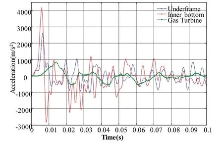
Fig.16 Acceleration time curve at shock wave period
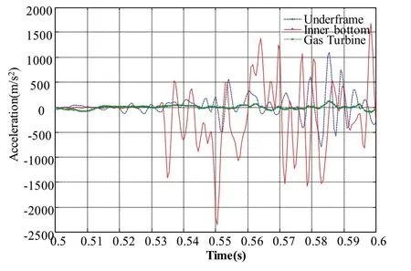
Fig.17 Acceleration time curve at bubble pulsation period
3 Conclusions
In this paper,the fluid-structure interaction model is established to investigate the dynamic responses of hull-gas turbine structure subjected to close-in non-contact underwater explosion based on Coupled Eulerian-Lagrangian Method.The damage characteristics of the hull-gas turbine under a certain condition are obtained,and the dynamic response of gas turbine and its base is analyzed.The conclusions are drawn as follows:
(1)The numerical model based on the Coupled Eulerian-Lagrangian method can capture the main features of all stages of underwater explosion well.Besides,the simulated environment is close to the actual working conditions,which proves that the model is effective in calculating underwater explosion loads;
(2)The damage mode of the hull-gas turbine structure subjected to underwater explosion loads can be divided into three cases:destruction of local structure,instability of base,and longitudinal instability caused by bubble pulsation load;
(3)Mises Stress and PEEQ caused by UNDEX bubble are more severe than those caused by shock wave in close-in non-contact UNDEX case.Therefore,it can be concluded that the equipment installed with vibration isolators can be severely damaged by bubble load;
(4)Vibration isolator can significantly reduce the impact generated by underwater explosion loads,and it is a reasonable arrangement.
杂志排行
船舶力学的其它文章
- Application of the Cell-vertex Finite Volume Method in the Solution of the Lubrication Characteristicsof Journal Bearings
- Numerical Simulations on the Dynamic Characteristicsof a Shallow-draft Spar-type Floating Wind Turbine
- Study on Torque Characteristics and Structural Strength of Large Container Shipsunder Oblique Waves
- Collapse Analysis of Model Sphere of Titanium Manned Cabin under External Pressure
- Study on the Performance of Micro-perforated Plate Absorber under Coupling
- Experimental Study on Characteristicsof Marine Propeller Cavitation and Noise
