Numerical Simulations on the Dynamic Characteristicsof a Shallow-draft Spar-type Floating Wind Turbine
2021-07-03,,,
,,,
(1a.State Key Laboratory of Mechanical Systemand Vibration;b.State Key Laboratory of Ocean Engineering,Shanghai Jiao Tong University,Shanghai 200240,China;2.School of Engineering,Newcastle University,Newcastle Upon Tyne NE1 7RU,United Kingdom)
Abstract:The dynamic characteristics of a shallow-draft spar-type floating wind turbine(FWT)system are investigated using the numerical code FAST.This FWT system is designed for harvesting wind power in a water depth of 150 m where the cost of energy is believed to be reasonable.A comparison between this FWT system and OC3-Hywind system in terms of their dynamic responses is presented firstly.The influence of wind on the dynamics of FWT system is then investigated.Finally,a comprehensive load-case analysis is performed for this FWTsystem.It is found that turbulence brings significant excitations around the natural frequencies of FWTsystem.Surge and pitch are dominated by rotor thrust.They are believed to couple with each other through the relationship between rotor thrust and relative wind velocity.And yaw is mainly determined by the yaw moment induced by rotor thrust when the platformis rolling.
Key words:floating wind turbine;Spar buoy;shallow draft;FAST;dynamics
0 Introduction
The scarcity of on-land installation sites and the public concern about noise pollution impose limitations on the development of land-based wind power.As a result,a substantial shift of the focus toward offshore wind energy has been made in recent decades[1].Currently,most offshore wind turbines are installed on the bottom-mounted substructures in shallow water area with a water depth of up to approximately 60 m[2].However,the bottom-mounted substructures are economically nonviable for deeper water sites where more offshore wind resources exist.In this context,a floating platform will be a better choice.
Floating wind turbines(FWTs)are still immature and a lot of research efforts have been put on developing a feasible floating support-platform configuration.The spar buoy is one of the primary concepts of floating platforms.Spar buoy platform achieves stability by using ballast weights in the low part of the floater which results in righting moments and high inertial resistance to pitch and roll[3].This is an advantage of spar buoy over other kinds of support platforms such as semi-submersible platform since large pitch motions will greatly weaken the energy capture capability of an FWT system.Furthermore,the simple structure of the spar buoy makes it easy to fabricate and allows for quicker implementation of numerical models and laboratory scale testing.The world’s first full-scale floating wind turbine‘Hywind’was installed in 2009 off the Norwegian coast at an average water depth of 220 m by Statoil[1].Based on this concept,a new FWT system,namely the OC3-Hywind system,was developed by the National Renewable Energy Laboratory(NREL)[4].The spar buoy platform of the OC3-Hywind system is an enlarged version of the Hywind platform and it is suitable for supporting the NREL 5-MWbaseline wind turbine.
Numerous studies have been performed for analyzing the dynamic characteristics of spar-type FWT system.Karimirad[5]utilized the HAWC2 code to investigate the stochastic dynamic response of a tension leg spar-type FWT.Sethuraman and Venugopal[6]carried out wave tank tests to measure the hydrodynamic response of a stepped-spar FWT under regular and irregular waves and employed the time-domain modelling tool,OrcaFlex,to validate the measured results.Solberg[7]conducted a thorough research on the dynamic response of OC3-Hywind system by using several codes,i.e.,HydroD,DeepC as well as TDHMILL3d.Simulation results showed that the FWT system was mostly influenced by wind loads.And the spar buoy platform experienced large yaw motionswhen wind and waves had different directions.
The NERL FAST(Fatigue,Aerodynamics,Structures and Turbulence)simulator is a well-recognized wind turbine dynamics analysis software[8].Offshore Code Comparison Collaboration(OC3)wasestablished to verify the accuracy and correctness of several aero-hydro-servo-elastic codes including FAST through the code-to-code comparisons[9].Jonkman and Matha[2]presented a comprehensive dynamic-response analysis on three FWT concepts(i.e.,three 5 MWwind turbines located on a tension leg platform,a spar buoy and a barge respectively)using FAST.The ultimate and fatigue loads induced by platform motions for all turbine components in the barge system were found to be the highest among three concepts.They also pointed out that instabilities in all systems need to be solved.Ma et al[10]utilized FASTto analyze the wind-wave induced dynamic response of OC3-Hywind system.They noticed that wind-induced loads mainly contributed to the low-frequency excitations.The coupling of surge and pitch due to wind and wave loads was also validated.
Although these studies presented the unique dynamic characteristics of spar-type FWT systems,the mechanisms behind these characteristics need to be investigated further,such as the relationships between loads and excitations and the causes of the coupling effects among different modes of motions.
It is noted that OC3-Hywind system has a draft of 120 m,thus it is suitable for a water depth of above 150 m.The water‘deeper than 150 m’is often associated with very far offshore locations and site accessing difficulties.For example,the water depths of sea areas within 200 kilometers off the coast of China are below 150 m[11].Further distance fromthe shore significantly increases the development and operation costs[1].Thus the area with a water depth of within 50~150 m is considered to be economically ideal since this area is not too far away from the shore and has a relatively sufficient amount of wind energy.For harvesting wind power in such water depths,the spar buoy platform of FWT system needs to have a shallower draft.A research group in Worcester Polytechnic Institute(WPI)developed a 100:1 scale model of shallow-draft spar-type FWT[12].The corresponding full-scale model has a draft of 60 m and its projected water depth is 150 m.Model tests were performed to find out the spar-buoy response in different wave conditions.However,comprehensive simulations on the dynamics of this kind of shallow-draft spar-type FWT system remain to be carried out to predict its characteristics in an actual ocean environment.This will provide valuable data for design and engineering practice.
This paper aims to present a thorough research on the dynamic characteristics of a shallowdraft spar-type FWT system.This new FWT concept is modified from the one described in Ref.[12]and its draft is 72 m.It is suitable for deployment in a water depth of over 100 m.In fact,the projected water depth of this new system is 150 m.The shallow-draft spar-buoy platform is designed to support the NREL 5MWbaseline wind turbine.The NREL-developed FAST is applied to enable coupled nonlinear aero-hydro-servo-elastic analysisin the time domain.
The remainder of this paper is organized as follows.The model and simulation method used in the present study are given in Chapter 1.The results and discussions are presented in Chapter 2.Finally,some concluding remarksare given.
1 Model and simulation method
1.1 Model description
Since the diameter of the tower base is smaller than that of spar buoy,a taper section is introduced to the WPI model to obtain the FWT concept investigated in this work.This taper section is similar to the one of OC3-Hywind spar buoy.This shallow-draft spar-type FWT system will be called as new system in this paper to distinguish it from the OC3-Hywind system.Fig.1 illustrates the configuration of new system.
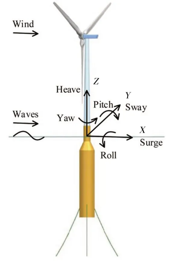
Fig.1 The sketch of new system
New system also uses the NREL 5MWbaseline wind turbine with a rotor diameter of 126 m,a hub height of 90 m and a rated wind speed of 11.4 m/s.The gross properties of this wind turbine can befound in Ref.[13].Tab.1 showsthe platformstructural properties of new system as well as those of OC3-Hywind system[4].It can be seen that the platform of new system has a smaller draft,a greater diameter and a larger mass.This can be attributed to the requirement of static stability of FWT system in a relatively shallow sea area.As mentioned above,the projected water depth of new system is 150 m.Thus,a typical mooring systemisdesigned for thiswater depth.Tab.2 summarizesthepropertiesof mooring system.

Tab.1 Floating platform structural properties of new system and OC3-Hywind system

Tab.1(Continued)

Tab.2 Properties of mooring system
1.2 Simulation method
The nonlinear time domain simulator,FAST,is employed in this work to analyze the FWT dynamics[14].FAST consists of several modules such as AeroDyn,ServoDyn,HydroDyn and Elasto-Dyn.
AeroDyn is an aerodynamic subroutine package which models rotor dynamics using the classic quasi-steady blade element momentum(BEM)theory or a generalized dynamic wake(GDW)theory[15].In this work,the BEM theory[16]is used to calculate aerodynamic loads.
The control scheme of wind turbine is defined in ServoDyn.For the NREL 5MW baseline wind turbine,two basic control systems are employed to control power-production operation[13].In the below-rated wind-speed range,the generator-torque controller works to maximize power capture.In the above-rated range,the blade-pitch controller is active to achieve constant generator speed.Under this control scheme,the resulting steady-state rotor thrust of the NREL 5MW wind turbine can be obtained by running a series of simulations with a steady wind velocity.The thrust curve is shown in Fig.2.Rotor thrust is the highest at the rated wind speed,i.e.,11.4 m/s.It is noted that the platform motions are disabled in these simulations.
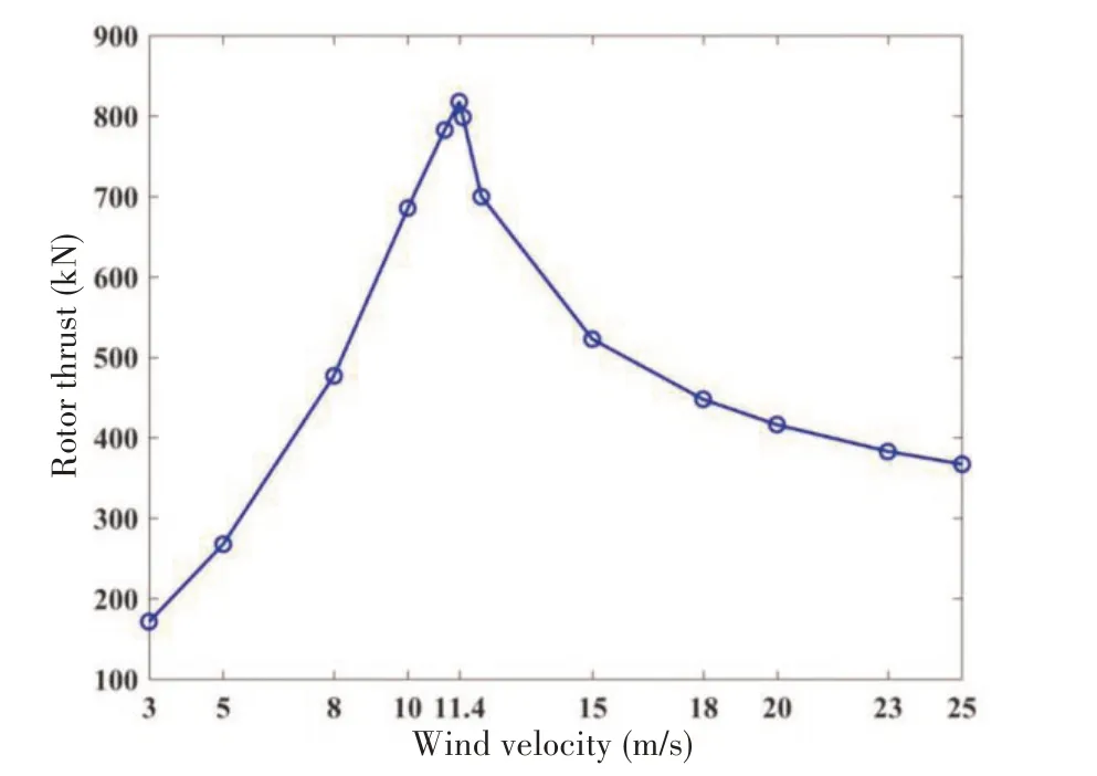
Fig.2 Rotor thrust curve of the NREL 5 MW baseline wind turbine
HydroDyn is a time-domain hydrodynamics module.It allows for multiple approaches for calculating the hydrodynamic loads on a structure such as potential flow theory or strip-theory[17].Under the assumption of linearization,the hydrodynamic problem can be divided into three separate problems:radiation,diffraction and hydrostatics[18-19].The linear potential-flow hydrodynamic radiation and diffraction problems are solved using the WAMIT computer program[20].The solution to the radiation problem is given in terms of oscillation-frequency-dependent added mass and damping coefficient matrices.And the solution to the diffraction problem is given as wave-exciting force and moment vector which dependson the incident wave frequency and direction.
It is noteworthy that the hydrodynamic calculations should be augmented with the nonlinear viscous-drag term form Morison’s equation[4,21].It is found that the oscillatory Reynolds number exceeds 105in most conditions of importance,that is,in moderate to severe sea conditions.Thus,the viscous drag coefficient,CD,is taken to be 0.6,which is considered to be a typical value for a cylinder at high oscillatory Reynolds numbers[22].
ElastoDyn is the structural dynamics solver which takes aerodynamic loads,hydrodynamic loads as well as controller commands as inputs and then outputs the displacements,velocities and accelerations of a number of structural degrees of freedom(DOFs).The Kane’s dynamics method is adopted to derive the equations of motion used in FAST[23].The complete nonlinear time domain equations of motion of the FWTsystem are of the general form,


There are 24 DOFs in the three-bladed FWT model.This work mainly focuses on the six rigid-body modes of motion of the support platform.These include translational surge,sway and heave displacement DOFs together with rotational roll,pitch and yaw displacement DOFs,as shown in Fig.1.
It is decided to run one-hour simulation.To account for transient start-up,the simulation time is augmented with 1 000 s.Thus,the total simulation time is then 4 600 s and the time series from 1 000 s to 4 600 s are selected to calculate the statistical values(i.e.,maximum value,minimum value,mean value and standard deviation)as well as power spectra.
2 Results and discussions
2.1 Free decay tests
Free decay tests are performed to find the natural frequencies of the FWT system.The decay test is done by moving the system out of its equilibrium position in one of its degrees of freedom and then releasing it.Tab.3 shows the results of free decay tests(i.e.,the natural periods(Tn)and the natural frequencies(fn)specified in Hz)of OC3-Hywind system together with the results provided by Matha[24].It can be found that there are little discrepancies between the results of this work and those in Ref.[24].The resultsof new system are shown in Tab.4.

Tab.3 Resultsof free decay tests of OC3-Hywind system

Tab.4 Results of free decay testsof new system in a water depth of 150 m
2.2 Comparison between new system and OC3-Hywind system
It is mentioned in Section 1.1 that the structural properties of spar buoy of new system are different from those of OC3-Hywind system.This section discusses the effect of spar-buoy structure on the dynamic behavior of FWT system.To achieve this,new system is placed in a water depth of 320 m which is the projected water depth of OC3-Hywind system.And a mooring system similar to the one of OC3-Hywind system is selected for new system.This ensures that the relationships between mooring line tension and the 6-DOFmotion of spar buoy are set to be the same for both FWT systems.It is worth noting that the natural periods of new system have changed since its original mooring system is replaced.The results of free decay tests of new system in a water depth of 320 m are listed in Tab.5.

Tab.5 Results of free decay testsof new system in a water depth of 320 m
Firstly,simulation cases are run with regular waves only.A series of incident wave periods are selected.Fig.3 shows the simulation results of these cases.These results are presented in the form of Response Amplitude Operator(RAO)which is defined as the amplitude of body motion in a certain mode in response to an incident wave of unit amplitude[18].

Fig.3 RAOversus incident wave period for the FWTsystem
For a certain FWT system,the RAOof surge or pitch is the highest when the incident wave period is close to the pitch natural period.Similarly,the RAOof heave reaches its highest value if the wave period is around the heave natural period.The RAO of new system is greater than that of OC3-Hywind system unless the wave period is close to the heave or pitch natural period of OC3-Hywind system.This indicates that new system has more intense dynamic response than OC3-Hywind system under the same wave condition.
Then,the two cases described in Tab.6 are investigated.The same wind and wave conditions are chosen for both cases,i.e.,irregular waves defined by JONSWAP spectrum and steady wind with a speed of 11.4 m/s at hub height(Vhub).The power spectra of surge,heave and pitch are presented in Fig.4.Case B has a higher spectrum density than Case A throughout the whole frequency region.This means that the new system experiences a greater intensity of dynamic response when it is excited by wind and wave loads.In fact,the change of spar-buoy structure leads to the changes of hydrodynamic loads and inertial properties of FWT system.All of these result in the differences in the dynamics of the FWTsystems.

Tab.6 General description of the simulation cases

Fig.4 Power spectrum comparison
2.3 Comparison of three load conditions
In order to investigate the influence of wind on the dynamic behavior of new system defined in Section 1.1,three different simulation cases are carried out.Tab.7 presents the details of these cases.The wave conditions of these cases are set to be the same.It is noted that Case 1 is run with waves only.In Case 3,TurbSim[25]is used to simulate the turbulence velocity.The time series of the wind field isgenerated by the use of the Kaimal spectrum[26]before time domain simulation starts.

Tab.7 General description of the simulation cases
Fig.5 shows the power spectra of three principal DOFs(i.e.,surge,heave and pitch)in the cases mentioned in Tab.7.In order to have a clear view of the wave frequency region(i.e.,the frequency region near the peak spectral frequency(0.111 Hz)),two ordinate axes are used with the left ordinate axis showing the low frequency region of power spectrum(below 0.07 Hz)and the right one showing the high frequency region(above 0.07 Hz).In this figure,0.017 Hz and 0.020 Hz are considered to be frequency components around surge natural frequency(0.021 Hz).0.028 Hz and 0.031 Hz are around heave natural frequency(0.028 Hz).0.046 Hz is around pitch natural frequency(0.052 Hz).And 0.103 Hz is around the peak spectral frequency of wave spectrum.
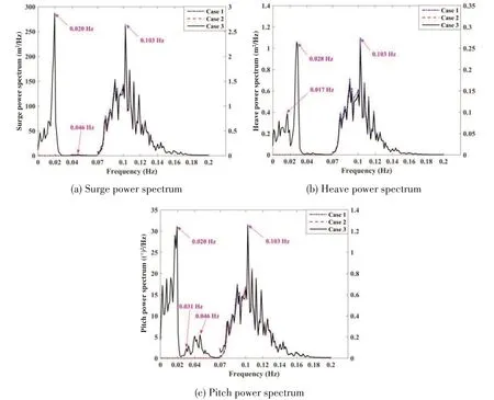
Fig.5 Power spectrum comparison
In Case 1,the excitations are mainly located in the wave frequency region.This indicates that the influence of wave forces/moments on the dynamic behavior of FWTsystem is mainly reflected in the wave frequency part of power spectrum.The excitations in wave frequency region are almost the same for all cases(i.e.,they overlap each other)due to the fact that the same wave conditions are defined.However,in Case 3,there are significant excitations in the low frequency region especially around the natural frequencies of surge,heave and pitch.In fact,there are also some excitations in the low frequency region of Case 2,but they are much smaller than those of Case 3 and cannot be seen clearly in Fig.5.Thus,a conclusion can be drawn that the loads induced by wind(mainly rotor thrust force)can bring about the low-frequency excitations of FWT system especially those around the natural frequencies of the system.What is more,compared with steady wind,turbulence can have much more significant influence on the low-frequency excitations.This kind of influence will be discussed further in the next section.Since the turbulence is closer to the in-site wind condition,all the casesdiscussed later will be run with turbulence.
2.4 Load case analysis
To study the dynamic response of the new system,suitable environmental conditions must be applied.The conditions need to be realistic and span through different severities of sea and wind state.The environmental parameters of a typical sea area near the Hainan Island are selected.The water depth of the reference site is above 100 m.These environmental parameters are based upon Ref.[11].
The chosen load cases(LCs)are listed in Tab.8.In total,there are 5 different cases that span a wide range of wind and wave conditions.There are variations in mean wind speed at hub height(Vhub),significant wave height(Hs),peak spectral period(Tp)as well as wind and wave directions.The 0°direction means that the waves and wind are moving along the positiveX-axis.The directional angles are defined positive in the counter-clockwise direction.Fig.6 illustrates the wind and wave directions as well as the location of mooring lines.

Tab.8 General description of load cases

Fig.6 Sketch of wind and wave directions and mooring line location
LC 1 is considered as a mild condition with a mean wind speed below rated.Motions of the FWT system are expected to be small for this case.LC 2 is situated at the rated wind speed(11.4 m/s).It includes three different load cases,i.e.,LC 2-a,LC 2-b and LC 2-c.The thrust curve in Fig.2 showsthat the thrust is at its maximum for this mean wind speed.LC 3 has aboverated mean wind speed.The mean thrust here is less than that of LC 2,even though the mean wind speed ishigher.
The corresponding wave and wind spectra of all load cases are plotted in Fig.7.From LC 1 to LC 3,the peak spectral period as well as significant wave height increases steadily.As a result,the wave spectrum spans an increasingly larger area.An increasing trend can also be seen in the density of Kaimal spectrum.Fig.7 shows that the waves in LC 1~LC 3 have no significant energy around the natural frequencies of new system,except yaw.Since the spar-buoy platform is symmetric,there will be no wave forces/moments that can directly excite yaw motion.However,for all cases,the Kaimal spectrum has significant densities situated around all the natural frequencies.
In LC 1,LC 2-a and LC3,the wind and waves propagate in the same direction which is the positive direction ofX-axis.Thus this kind of load case is called as collinear case.In contrast,LC 2-b together with LC 2-c are defined as non-collinear case since there is an offset in wind and wave directions.
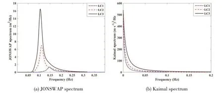
Fig.7 Wave and wind spectra of all load cases
In Sections 2.4.1-2.4.2,the frequency region of power spectrum is divided into two parts,i.e.,the low frequency region and the high frequency region.The low frequency region ranges from 0 to 0.07 Hz.The natural frequencies of new system(except for yaw)lie in the low frequency region.The high frequency region refers to frequencies above 0.07 Hz.And the peak spectral frequency(0.147 Hz in LC 1,0.111 Hz in LC 2 and 0.105 Hz in LC 3)of wave spectrum locates in this region.In the high frequency region,the frequency zone around 0.103 Hz is regarded as the wave frequency region.The corresponding frequency components of natural frequencies of new system in the power spectrum are shown in Tab.9.

Tab.9 Corresponding frequency components of natural frequencies in the power spectrum
2.4.1 Collinear cases
Fig.8 shows the statistical values and power spectra of surge,heave,pitch,rotor thrust as well as fairlead tension in collinear cases.In order to show the wave frequency region in surge power spectrum clearly,the method mentioned in Section 2.3 is also adopted here,that is,two ordinate axes are used.It is worth mentioning that the standard deviation of time series of six-DOF motion represents the intensity of motion.
The mean surge and pitch positions are dominated by the mean thrust force.The mean thrust force is at its highest(about 749 kN)in LC 2-a.Similar trends can also be seen in the variations of mean positionsof surge and pitch.
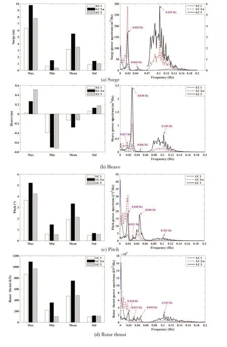
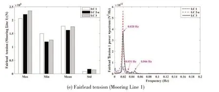
Fig.8 Statistical values and power spectra of collinear cases
In the surge spectrum,there are excitations around the surge natural frequency with some small contributions around pitch natural frequency.The excitations from the waves are very small compared to those in the low frequency region.Pitch excitations follow a similar pattern as surge.However,there are small excitations around the heave natural frequency in pitch spectrum.
Most of the excitations in the low frequency part of surge/pitch power spectrum are believed to be induced by thrust.Rotor thrust is determined by the relative velocity between wind and rotor,that is,the difference of incoming wind velocity and rotor velocity.The Kaimal spectrum indicates that the main energy of turbulence lies in the low frequency region.And rotor velocity is mainly determined by the six-DOF motion of support platform.As previously mentioned,the natural frequencies of new system are also within the low frequency region.Thus the main frequency components of rotor thrust are those in the low frequency region.This kind of rotor thrust is considered to contribute to the low-frequency excitations.Since the density of Kaimal spectrum in LC 1 mainly concentrates on a relatively small region below 0.05 Hz,there exists a large component around 0.001 Hz in the rotor thrust spectrum of LC 1.This component can also be found in the surge and pitch power spectra of LC 1.
Furthermore,there exists a coupling effect between surge and pitch due to the relationship between rotor thrust and relative wind velocity.This coupling effect can be learnt from the excitations around pitch natural frequency in surge spectrum and the excitations around surge natural frequency in pitch spectrum.In fact,surge and pitch will change the relative velocity between incoming flow and rotor.This causes a variation in rotor thrust and influences surge and pitch in turn.Thus,surge and pitch couple with each other through the relationship between rotor thrust and relative wind velocity.
With the sea state severity increasing from LC 1 to LC 3,the excitations from the waves in surge and pitch spectra also increase.Due to the relationship discussed above,this also leads to an increase in the wave frequency part of rotor thrust spectrum.In fact,there are significant wave frequency components in the rotor thrust spectrum of LC 3.
In surge power spectrum,the excitations around surge natural frequency in LC 1 and LC 3 are lower than those in LC 2-a.This can be related to the same variation in the density of thrust spectrum around surge natural frequency.The same phenomenon can also be seen in the density variations of pitch and thrust spectra around pitch natural frequency where both of them increase steadily from LC 1 to LC 3.The total energy of surge as well as that of pitch(i.e.,the standard deviation of its time series)increase to a maximum in LC 2-a.This can also be related to the fact that the standard deviation of rotor thrust hasa maximum value in LC 2-a.
The FWT system experiences small excitations in heave for all the load cases.The negative mean position in heave results from the rotor shaft tilt(5°)and the positive mean position in pitch.Both of them cause some of the rotor thrust to act downward.And the standard deviation of heave increasestogether with the sea state severity since the heave isalso influenced by wave forces.
The rotor thrust is counteracted by tensions in the mooring lines,with the downstream mooring line(i.e.,Mooring Line 1)lessloaded than the upstreamlines(i.e.,Mooring Line 2 and Mooring Line 3).In the tension spectrum,it is the low frequency part that is the main contributor for all cases,especially the region around surge natural frequency.There are also some small excitations around the heave and pitch natural frequencies.This indicates that fairlead tensions are mainly determined by surge.The largest tension standard deviation is in LC 2-a.This is also the case when the surge standard deviation is at its maximum.The lowest mean tension of Mooring Line 1 is found in LC 2-a.Thisisalsothecase when themean thrust aswell asthe mean surge position isat itshighest.
2.4.2 Non-collinear cases
The results of the non-collinear cases are shown in Fig.9.The statistical values of rotor thrust remain stable despite the increasing wave incident angle from LC 2-a to LC 2-c.The mean position of pitch in LC 2-b and LC 2-c is basically unchanged from its corresponding collinear case(i.e.,LC 2-a)since it is mainly the mean thrust force that influences this DOF.The standard deviation of pitch is also not greatly influenced by wave incident angle.For the pitch and rotor thrust spectra,the small changes are in the wave frequency region where the excitations are reduced with an increasing wave incident angle.Similar trends are also found in the statistical values and power spectrum of surge.There are nearly none excitations within the wave frequency region in LC 2-c when waves propagate along the positiveY-axis.This can be attributed to the fact that wave forces/moments have no influences on the surge and pitch DOFs in this case.Heave is not shown in Fig.9.However,it is worth mentioning that heave motion is,as before,not excited much,and there are no large differencesin the statisticsbetween collinear and non-collinear cases.


Fig.9 Statistical values and power spectra of non-collinear cases
The roll DOF is naturally more involved when waves are no longer propagating along the positiveX-axis.The standard deviation of roll increases with wave incident angle.This is related to the increase of wave frequency part in roll power spectrum since wave moments have a greater influence on roll.
There are two main effects that can provide moments around theZaxis of the reference coordinate system,resulting in excitations in yaw[7].The first one is the gyro moment from the spin of the rotor when the support platform is pitching.Secondly,if the support platform rolls,there will be an arm from the origin of the reference coordinate system to the position of the thrust force,resulting in yaw moment.The thrust induced yaw moment is believed to be the most important contributor to the yaw motion.
Yaw motion is the largest in LC 2-c.Studying the power spectrum of yaw in LC 2-c,two contributions in yaw are visible.There is a double peak around 0.045 Hz as well as a larger wave frequency region which also stretches around yaw natural frequency of 0.112 Hz.The double peak coincides with the roll and pitch natural frequency.The contributions of density around 0.045 Hz are considered to be a combined effect of coupling in yaw through the gyro moment with pitch and thrust with roll.It is mentioned above that for LC 2-c pitch does not oscillate with frequencies in the wave frequency region,while roll does.Due to the roll motion,the thrust force induces moment about theZaxis,resulting in excitations in the wave frequency region including the yaw natural frequency.The excitations in the region below pitch/roll natural frequency is believed to be induced by the rotor thrust since similar frequency components can also be found in the power spectrum of rotor thrust.
3 Conclusions
The dynamics of a shallow-draft spar-type FWT system have been investigated.A series of simulation cases are run in different kinds of wind and wave conditions using FAST.The main conclusionsare summarized asfollows:
(1)To achieve static stability in a relatively shallow sea area,the spar-buoy platform of FWT system needs to have a smaller draft,a greater diameter and a larger mass.As a result,under the same wind and wave conditions,this new FWT system has a greater intensity of dynamic response than the OC3-Hywind systemif they are placed in the same water depth.
(2)The excitations in the wave frequency region of power spectrum are found to be caused by wave loads.The loads induced by turbulence(mainly rotor thrust force)can bring about significant excitations around the natural frequenciesof FWTsystem.
(3)The mean positions of surge,heave and pitch are dominated by the mean thrust force.Most of the excitations in the low frequency part of surge/pitch power spectrum are also induced by thrust.Surge and pitch are considered to couple with each other through the relationship between rotor thrust and relative wind velocity.And the fairlead tensions are mainly determined by surge motion.
(4)The statistics of surge and pitch remain basically unchanged despite the increasing wave incident angle.In contrast,the intensity of roll increases with wave incident angle.Yaw is believed to be excited by two main effects,i.e.,the gyro moment and the thrust induced yaw moment.The latter one isconsidered to be the main contributor.
杂志排行
船舶力学的其它文章
- Application of the Cell-vertex Finite Volume Method in the Solution of the Lubrication Characteristicsof Journal Bearings
- Study on Torque Characteristics and Structural Strength of Large Container Shipsunder Oblique Waves
- Collapse Analysis of Model Sphere of Titanium Manned Cabin under External Pressure
- Numerical Investigation of Dynamic Responsesof Ship Structure and Gas Turbine Subjected to Underwater Explosion
- Study on the Performance of Micro-perforated Plate Absorber under Coupling
- Experimental Study on Characteristicsof Marine Propeller Cavitation and Noise
