Collapse Analysis of Model Sphere of Titanium Manned Cabin under External Pressure
2021-07-03,,,
, ,,
(1.China Ship Scientific Research Center,Wuxi214082,China;2.State Key Laboratory of Deep-sea Manned Vehicles,Wuxi214082,China;3.Shanghai Engineering Research Center of Hadal Science and Technology,Shanghai Ocean University,Shanghai 201306,China;4.School of Mechanical Engineering,Jiangnan University,Wuxi 214122,China)
Abstract:Before the final design of a deep-sea manned cabin,some small model spheres are generally made for test in a pressurized chamber to check the capabilities of the material and structure and provide reference for improvement of design.In this paper,the failure analysis and fracture surface observation on a pressurized Ti-6Al-4V ELImodel sphere are conducted,and the failure scenario of the model sphere is explained by finite element simulation.It is shown that localized yielding occurs first in the vicinity of the forged component,and the folding with tearing takes place along the radial direction from the welding line of the forged component,which will be separated completely from the north hemisphere together with several fractured pieces.The finite element simulation can be used as a reference for further dynamic or impact analysis of manned cabins.
Key words:manned cabin;model sphere;collapse analysis;titanium alloy
0 Introduction
As a pivotal component of deep-sea submersibles,the manned cabin is designed with enough strength to provide a safe living space for pilots and scientists[1-3].The form of a thick spherical hull with several large openings is typically adopted for deep-sea manned cabins,which is generally manufactured by hemisphere punch and equatorial welding or by welding several spherical parts and the opening strengthening components together.
To insure the safety of a designed manned cabin,small model spheres made of the same material and manufactured by similar techniques are usually developed for collapse tests to check the failure mode of the sphere and the reasonability of the design method.As for the newly-developed manned submersible(4500 m depth)[4-6],a type of beta-annealed titanium alloy Ti-6Al-4V(extralow interstitials,ELI)[7]is used for the manned cabin.A model sphere made of Ti-6Al-4V ELIwith an inner diameter of near 500 mm is manufactured by two hemispheres punched and welded together.One opening is made in one of the hemispheres and strengthened by a forged component.The model sphere is put in a pressure chamber to verify the material,manufacture capability and the collapse strength.In the chamber,the collapse pressure is recorded,and its fracture morphology when taken out after failure is analyzed for failure mode.The analysis results can be used by designers as a reference to improve their design methods[4-5].
To save the cost of validation tests,finite element(FE)simulation may be used as an aid to design the cabins at a primary design stage.A reasonable FE model is very important for precise results.The dynamic collapse simulation can be carried out to explain the collapse mode and mechanism,which can be found in literatures as failure explanation illustration[8].During the collapse simulation,the material nonlinearity,the average hull thickness,the out-of-roundness of the sphere,the welding,and the forged opening strengthened component should be considered thoroughly.
In this paper,the model test procedure and results on a 500 mm sphere were illustrated first,and its failure process and failure mode were explained by fracture analysis of the debris.FE simulation was done in combination with fracture strain dependency on mesh and small specimen tests on dynamic material properties.FEsimulation results were compared with model test results.Model test,fracture analysis and FE simulation show that collapse beginning near the weakest point of the hull is caused by thinnest shell and strength reduction of welding joint.The simulation results provide valuable information for the improvement of design methods and manufacturing techniques.
1 Model test
A small model sphere made of Ti-6Al-4V ELI titanium alloy was manufactured.Ti-6Al-4V ELIis a beta-annealed Ti-6Al-4V(extra-low interstitials,ELI),and Fig.1(left)shows the designed geometry dimensions.Then the model sphere was tested to collapse and its collapse strength and failure mode were investigated.The model sphere was made by two punched parts,with the north hemisphere and the south hemisphere welded together,and there was an opening in the north hemisphere,where it was strengthened by a forged component welded to the hemisphere.An opening cover wasfastened duringtest.Thematerial propertiesof the baseand weld material were experimentally studied during the manufacture processof the model sphere with theresultslisted in Tab.1.

Fig.1 Designed geometry dimensions of the model sphere and its loading phases used in model test

Tab.1 Mechanical properties of base and weld material in room temperature
The thickness of the sphere in different positions were measured using ultrasonic thickness gauge with the measurement precision of 0.01,which had been calibrated correctly.The out-ofroundness was measured by three coordinates measuring instrument.Results showed the thickness ranges were 9.28-9.47 mm(average value of 9.376 3 mm)in north hemisphere and 9.06-10.1 mm(average value of 9.243 6 mm)in south hemisphere respectively.Detailed data would be applied in FEsimulation of the paper.
After test preparation,the model sphere with strain gauges pasted on it was sent to the pressure chamber,and the watertight and insulation tests were carried out in two tentative loading phases as shown in Fig.1(right).The third loading phase was carried out gradually with the step of a pressure increase of 5 MPa,and the original stage were maintained for 3 min..Normally the step of pressure increase is reduced to 3 MPa,1 MPa or even 0.5 MPa to capture the actual collapse pressure as accurately as possible,then the pressure is increased near to the predicted collapse pressure or till significant nonlinear strain-stress relation appears.The comparison between the photographic illustration of the sphere before and after collapse is shown in Fig.2.And the collapse pressure is 55 MPa.For more details,reference can be made to Pan et al[5].

Fig.2 Photographic illustration of the sphere before and after collapse
2 Fracture analysis
The morphology of the fractured sphere after stability test under high pressure showssevere deformation and the sphere split to several pieces from the vicinity of the opening strengthened component.The sag area shown in Fig.3 includes the opening strengthened component together with the opening cover.The model sphere was made of high strength titanium alloy with a relatively low fracture toughness.Very high shear stress in the vicinity of the strengthened part approached the shear yield strength of the material and led to this result.During the buckling deformation,the stress state of the sphere mutated and cracking occurred in the vicinity of welding line with a relatively larger stiffness.The pressure on the sag area caused the cracks to propagate in all directions.At the same time,concaves also occurred in the other parts under external pressure and a plenty of small cracks gradually tore the sphere,but the crack propagation paths changed along with the sudden change of stressstatesand then cross-linked to form several separated debris.
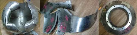
Fig.3 Morphology of the fractured sphere and one of separated debris
And from Fig.3,it can be noticed that the flange and the sphere body were completely separated.The three pieces of debris in Fig.3 were separated between the equatorial weld and the flange weld,indicating that they included both the base and weld materials.It can be estimated that the cracks initiated in the vicinity of the two welds.The fracture surfaces of one of the three typical pieces of debris in the positions of the base and weld materials are shown in Fig.4.The vast majority of the cracking section kept straight as a tearing surface but the variation of the direction of cracking made some sections with complex shapes.The fracture morphology paralleling with the weld bead(Fig.3 right)shows a normal fracture surface with non-uniform microstructure caused by the resultant force of tension and tear.

Fig.4 Imagesof fracture surfaces in base and weld materials
3 FE simulation
The collapse process of the sphere is simulated using the commercial simulation software ANSYS/DYNA,in which the fracture takes place when the criterion in terms of strainεeq≥εfcis satisfied.εeqis the equivalent maximum tensile strain at a finite element andεfcis the critical fracture strain specified for the finite-element simulation.
The stress-versus-strain relationship(σtversusεt)of the material used for the finite-element modeling is obtained by transformation of engineering(or nominal)stress-versus-strain relationship(σeversusεe),which can be expressed byσt≈σe(1+εe)andεt≈ln(1+εe).σtis the true stress allowing approximately for Poisson-ratio thinning;εtis the true strain representing integral of change in length over instantaneous length;σeis the engineering stress being given as force divided by unstressed area;andεeis the engineering strain representing change in length divided by initial length.
However,the value of the critical fracture strainεfcused for finite-element simulation should vary with the mesh size.When the mesh size is infinitely small,the critical fracture strainεfcmay be several times larger than the nominal fracture strainεfobtained from material tensile coupontest results,and it approaches the same value ofεfas finite-element size increases.According to Paik and Thayamballi[8],the normalized critical fracture strainεfc/εfcan be expressed as a function of element size which can be expressed by its aspect ratiot/s,wheresis the mesh size(length)andtis the thickness of the plate(or specimen)in the structure.A series of finite element simulations on tensile tests have been conducted to determine the dependency function,which can be expressed by power law as shown in Fig.5 for the base and weld material respectively.The fine mesh size with an aspect ratio of 1.0 is recommended to keep the integrity of the structure and capture the deformation patterns after local failure.

Fig.5 Critical fracture strain versus mesh size for base material(left)and weld material(right)
Meanwhile,it is noted that the nominal fracture strain is significantly dependent on the strain rate and structural deterioration among other factors.And the dynamic yield strength of the material will be changed with the strain rate.Different constitutive models have been proposed over the last few decades describing the dynamic material behavior[9-10].In this paper,the dynamic yield strength of the material is experimentally studied with the strain rate in the region from 1E-5 to 1.0,which is enough for the simulation on the sphere collapse,and its strain rate sensitivity function isexpressed by the equation listed in Fig.6.

Fig.6 Dynamic yield strength(normalized by the static yield strength)versus strain rate for Ti-6Al-4V ELI
Finite-element simulations are then conducted with the critical strain as the failure criterion determined in Fig.7.During finite-element simulation,theout-of-roundness(OOR)of thehull measured is modeled,which means it takes the geometry defect into account.The solid elements are used and will be deleted when their critical strain reaches the critical value,so the mesh size should be fine enough to keep the integrity of the structure and capture the deformation patterns after local failure.Furthermore,it is better to keep the whole mesh uniform in order to use the same failure strain for all the elements.And the cubic shape of the elements is adopted with the aspect ratio close to 1.0,which means that the element side length in the surface is the same as the thickness of 9 mm.
Fig.7(a)shows the deformation pattern of the sphere in the initial stage of collapse stage while Fig.7(b)shows the folding and tearing pattern of the sphere with localized yielding in the final stage of collapse.It can be seen that the mesh size adopted for simulation is fine enough to capture the deformation and tearing pattern of the sphere.With the pressure increasing with time,localized yielding occurs first in the vicinity of the forged component,and the folding with tearing takes place along the radial direction from the welding line of the forged component,which will completely separated from the north hemisphere together with several pieces in its vicinity.The collapse scenario as shown in Fig.7(b)is just similar to the test results in Fig.2.It is assumed that the failure strength is reached when the sphere loses its ability.The failure strength is about 51.8 MPa,which is a bit higher compared with the test result of 51 MPa and the error is about 6%.

Fig.7 Deformation and tearing patterns of the sphere
4 Concluding remarks
In this paper,the test on a 500 mm Ti-6Al-4V ELImodel sphere is presented.and the analysis of the fracture sphere is conducted to explain its failure mode.Dynamic collapse simulation is carried out and compared with model test results.The simulation shows that when the model sphere is pressurized in a chamber,localized yielding occurs first in the vicinity of the forged component,and the folding with tearing takes place along the radial direction from the welding line of the forged component,which will be separated completely from the north hemisphere together with several pieces in its vicinity.More detailed fracture analysis on separated pieces of debris further explains the failure process.The FE simulation results,which have similar collapse load and failure scenario with the test results,can serve as a reference for further dynamic or impact analysis of manned cabins.
杂志排行
船舶力学的其它文章
- Application of the Cell-vertex Finite Volume Method in the Solution of the Lubrication Characteristicsof Journal Bearings
- Numerical Simulations on the Dynamic Characteristicsof a Shallow-draft Spar-type Floating Wind Turbine
- Study on Torque Characteristics and Structural Strength of Large Container Shipsunder Oblique Waves
- Numerical Investigation of Dynamic Responsesof Ship Structure and Gas Turbine Subjected to Underwater Explosion
- Study on the Performance of Micro-perforated Plate Absorber under Coupling
- Experimental Study on Characteristicsof Marine Propeller Cavitation and Noise