Study on the Characteristics of Conformal Rudders and Their Influence on Vertical Plane Maneuver of Submarines
2021-07-03LUOFeiyng
, ,LUOFei-yng
(a.College of Ship and Ocean;b.National Key Laboratory of Science and Technology on Vessel Integrated Power System,Naval University of Engineering,Wuhan 430033,China)
Abstract:A conformal rudder is a new kind of submarine stern control surface composed of a fixed fin and a rotatable rudder.Water tunnel test and numerical simulation based on RANSmethod were carried out to investigate the open water hydrodynamic performance of a conformal rudder.It is found that sealing the gap between the rudder and the fin can effectively improve the hydrodynamic performance of the rudder by suppressing the flow separation.The rudder lift increases with chord ratio and aspect ratio.Simulation was carried out to study the maneuvering in the vertical plane of the submarine equipped with a conventional rudder,a conformal rudder and a gap-sealed conformal rudder respectively.The results indicate that the conformal rudder and the gap-sealed conformal rudder can increase the diving-surfacing angle of the submarine model by 65%and 105%respectively at a rudder angle of 5°.
Key words:submarine;conformal rudder;manoeuverability;computational f luids dynamics;water tunnel test
0 Introduction
Rudders are the main steering device of most marine vessels including submarines,other underwater vehicles and ships of all sizes.The design of rudders is always a hot issue in the study of maneuverability.
The performance of a rudder is affected by the design choices.Molland and Turnock[1]systematically introduced the rudder design strategy and design application.Kim[2]proposed rudder design procedure based on investigation of rudder design process at major Korean shipyards.Liu and Hekkenberg[3]reviewed the design choice of rudders and the impacts on the maneuverability of marine vessels.
The rudder profile has a great impact on the hydrodynamic performance.NACA,wedge-tail and IFSare all famous profiles with a high performance.Schilling rudder is also a kind of high efficiency airfoil rudders[4].Liu,Quadvlieg and Hekkenberg[5]studied the impacts of the rudder profile on maneuvering performance.
The flapped rudder is a kind of high lift rudders derived from the design of aircraft wings.It is made up of two portions.The forward portion can be considered as an all-movable spade rudder,with the aft portion an independently adjustable flap hinged from the forward part.Its hydrodynamic characteristics were studied systematically by experimentsand numerical simulation[6-9].
Because the control surface not only provides the steering force,it also provides stability to the submarine,the stern control surface of many submarines consists of two portions.The forward portion is a fixed fin(stabilizer)attached to the hull for improving the stability of submarines and providing protection for the rotatable rudder.The aft portion is a rotatable rudder for providing steering force,which is similar to the flapped rudder,but not exactly the same.
As for the conventional submarine stern control surface(called“conventional rudder”hereinafter),the rotatable rudder has a complete airfoil profile as shown in Fig.1.To reduce the power of the steering gear,the rudder stock is located at the hydrodynamic center.There is a break between the fin and the rudder.Wu′s study[10]concluded that this layout resulted in the reduction of rudder efficiency in the case of small deflection angle,as the leading edge of the rudder is in the wake flow of the fin.
To solve these problems,some submarines are equipped with conformal rudders,a kind of control surface with a new layout of fin and rudder,as shown in Fig.2.The main characteristic of a conformal rudder is that the gap between the fixed fin and the rotatable rudder is very small,and the two parts form a complete airfoil profile together.The outline of the conformal rudder remains smooth during the rotation.
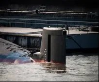
Fig.1 Conventional rudder

Fig.2 Conformal rudder
Liu,Xiong and Ye[11]compared the open water hydrodynamic performance of conformal rudders and conventional rudders.The results indicate that the layout of a conformal rudder can effectively increase the lift of the control surface and reduce the turbulent kinetic energy in the wake zone of the conformal rudder.Zhai[12]studied the hydrodynamic performance and wake field quality of a conformal rudder under the influence of the submarine hull.These studies were carried out in a steady state,which is just the initial state of maneuvering motion.
However,the effects of some parameters on hydrodynamic characteristics of conformal rudders and the influence of conformal rudders on the maneuver of submarines are not well understood.In this study,test and CFD(Computational Fluid Dynamics)research were carried out to study the influence of theCR(chord of rotatable rudder/total chord),AR(span/chord)and sealing of the gap between the fin and the rotatable rudder on the open water hydrodynamic characteristic of the conformal rudder.The maneuver on the vertical plane of submarine equipped with‘s’conformal rudder and‘s’conventional rudder were also studied and compared.
1 Hydrodynamic test of conformal rudders
At present,CFD cannot accurately simulate the stall at a high angle of attack.Therefore,it is necessary to carry out experiments to study the stall angle of conformal rudders and to verify the validity of numerical simulation.
1.1 Configuration of test models
In order to study the hydrodynamic characteristic of conformal rudders,three conformal rudders with different chord ratios(CR,chord of rotatable rudder/total chord)were designed based on NACA0015 airfoil profile.The section and picture of the rudders are shown in Figs.3~4.The leading edge of the rotatable rudder is a semicircle,and the rudder stock is at the center of the semicircle.The gap between the fin and the rudder is held constantly at 1 mm during the rudder rotation.The parameters of rudders are shown in Tab.1.

Fig.3 Section of conformal rudder

Fig.4 Test models
In addition,It is difficult to predict the flow in the gap between the fin and the rudder of the conformal rudder because the gap is very small.The existence of the gap may have an impact on the hydrodynamic performance of the rudder.Therefore,tests were also conducted with the gap between the fin and the rudder sealed.

Tab.1 Parameters of rudders
1.2 Test approach
The experiments were carried out in the water tunnel of the Naval University of Engineering.The dimensions of the rectangular test section are 0.6 m(height)×0.6 m(width)×2 m(length).The Reynolds number(Re)based on chord length can be changed by changing the free stream velocity(Vin).TheReof the test are 3.2×105,4.4×105and 6.2×10⁵.The installation of the rudder force dynamometer and the rudder model in the water tunnel is shown in Figs.5~6.The total lift of the fin and the rudder was measured by the rudder force dynamometer.

Fig.5 Installation of the rudder force dynamometer
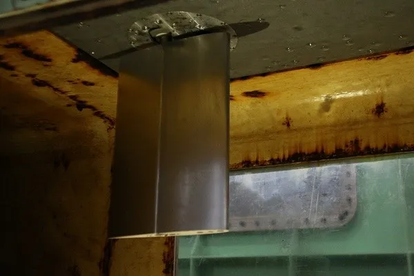
Fig.6 Installation of the rudder model
1.3 Test result and discussion
Rudder lift is non-dimensionalized using the free stream velocity:

whereL,ρ,VinandAare lift force,fluid density,free streamvelocity and the control surface area,respectively.
TheCLof three models with different chord ratios are shown in Fig.7.The slope ofCLcurve of the conformal rudder increases with the deflection angle linearly.And it begins to decrease after the deflection angle exceeds a critical angle of 10 to 20 degrees,but theCLstill increases with the deflection angle.This is different from an all-movable rudder,where the lift coefficient curve maintains a slope to stall and then the lift decreases[13].What’s more,the slope within the critical angle increaseswith the chord ratio.

Fig.7 C L of three test models with different chord ratios
When the deflection angle of the rudder is within the critical angle,the sealing of the gap between the rudder and the fin has little impact on the lift curve slope.But it delays the emergence of the critical angle for 5 to 10 degrees.Therefore,theCLof the conformal rudder increases obviously by sealing the gap when the rudder angle exceeds the critical angle.This is because the flow from the pressure surface to the suction surface in the gap is prevented,and the flow separation of the suction surface is slowed down.It is necessary to seal the gap in the use of the conformal rudder.
Lmis the amplitude of lift andLais the average of lift.Fig.8 and Tab.2 show the lift test result of the sealed gap rudder with a chord ratio of 0.5.It shows thatLm/Lais small when deflection angle is between 10 and 15 degrees,and it is significantly increased to 20 degrees,while the slope ofCLis decreased.The increase ofLm/Lareflects the increase of disturbance and pulsation in the flow field when the critical angle is exceeded,which leads to the decrease of the slope ofCLcurve.

Tab.2 L m and L m/L a of sealed gap rudder with C R of 0.5
Fig.9 shows theCLof the sealed gap rudder with a chord ratio of 0.5 in different Reynolds numbers.The influence of increasingReon hydrodynamics is similar to that of sealing the gap.HigherRecan delay the emergence of the critical angle,and theCLcurve slope does not change withRebefore the critical angle.Thus,the hydrodynamic performance of the conformal rudder improves with the increase ofRe.

Fig.8 Lift test result of the sealed gap rudder with C R of 0.5

Fig.9 C L of the sealed gap rudder with C R of 0.5 at different Re
2 Open water numerical simulation
In order to study the influence ofCRandARon the hydrodynamic performance and flow field of the conformal rudder,open water numerical simulation was carried.Because sealing the gap between the fin and the rudder can obviously improve the open water hydrodynamic performance,only the sealed gap rudder wasstudied.
2.1 Numerical methods
STAR-CCM+,a RANS(Reynolds Average Navier-Stokes)based CFD solver,was used to investigate the hydrodynamic performance and flow field of the conformal rudder.In all the simulations,the realizablek-εturbulence model was applied.
The computational domain and boundary conditions for simulation are:
(1)The upstream boundary of the computational field is at 5 times chord length upstream to the rudder and isset asvelocity inlet.The free streamvelocity is 2.2 m/s;
(2)The downstream boundary of the computational field is at 10 times chord length downstream to the rudder and is set as pressure outlet;
(3)The left boundary and right boundary are both at 5 times chord length beside the longitudinal plane of the rudder and are set asno-slip wall;
(4)The top boundary isconnected tothe rudder and isset asno-slip wall;
(5)The bottom boundary is below the top boundary with 3.3 times span length,and is set as no-slip wall;
(6)The rudder surface isset asno-slip solid wall.
TheRebased on chord length is 4.4×10⁵.
The total number of calculation grid cells is between 4 million and 7 million.The test domain is shown in Fig.10,and the mesh isshown in Fig.11.

Fig.10 Computational domain

Fig.11 Mesh detail
2.2 Numerical methods validation
Fig.12 shows the comparison between CFD results and experimental results of theCLof the conformal rudder.The simulation results agree well with those of the water tunnel experiment,except for the rudder withCRof 0.7 at a deflection angle of 25 degrees.Numerical calculations overestimate the lift coefficient before the slope drops for the rudder with a chord ratio of 0.5 and a chord ratio of 0.7,which may be caused by the 5 mm root gap between the rudder root and the tunnel wall in the model test.Nevertheless,the numerical calculation can basically capture the critical angle and theCLcurve slope within a deflection angle of 20 degrees.When the deflection angle is less than 20 degrees,the calculation iscredible.

Fig.12 Comparison between CFDresults and experimental results of the C L
2.3 Influence of chord ratio
Not only does the rotatable rudder provide lift,but the fixed fin also provides a significant portion of lift.It is necessary to study the effect ofCRon hydrodynamic performance.The three test model rudders and two rudders with theCRof 0.4 and 0.6 were studied by means of CFD.The schematic diagram of lift(L),drag(D)and torque(T)is shown in Fig.13.The hydrodynamic performance of rudders with differentCRis shown in Fig.14.The lift-drag ratio(L/D)and torque coefficient(CT)are dimensionless,and torque coefficient is expressed as follows:

Fig.13 Schematic diagram of hydrodynamic forces

whereT,ρ,Vin,A,andcare torque,fluid density,free stream velocity,the control surface area and chord length,respectively.

Fig.14 Hydrodynamic performance of rudders with different chord ratios
The critical angle of all the five rudders is about 15 degrees.TheCLis basically linear before the critical angle and the slope reduces when the defection angle exceeds the critical angle.Although the angle interval is 5 degrees,it can be seen thatCRdoes not have great impact on the critical angle.CLincreases withCRat all the degrees.
L/Dincreases withCRat small angles and decreases with increasingCRwhen the deflection angle exceeds 10 degrees.CTincreases rapidly withCRbecause the force on both the rotatable rudder and the moment arm increases withCR.AlthoughCLalways increases withCR,it increases slowly afterCRexceeds 0.5,and the increase ofCTis more obvious.Excessive rudder torque will bring many difficulties to the design of rudder stock and steering gear.Therefore,CRgreater than 0.5 should be used with caution.
Fig.15 illustrates the flow field at the spanwise middle section of the rudder with a chord ratio of 0.5.When the rudder angle is 10 degrees and 15 degrees,the flow separation is relatively weak,while at 20 degrees,which exceeds the critical angle,the flow separation is obvious.It is like the stall phenomenon of an airfoil that the flow separation causes the lift reduction.

Fig.15 Flow field at the spanwise middle section of the rudder with a chord ratio of 0.5
2.4 Influence of aspect ratio
Fig.16 shows the effect of aspect ratio on hydrodynamic coefficient.TheCLis basically linear when the deflection angle is within 15 degrees,and the slope decreases beyond this angle.A rudder with a higher aspect ratio has a higher slope before 15 degrees,but it also drops faster after 15 degrees.As for the rudder with an aspect ratio of 0.5,the curve is linear until 20 degrees,and its flow field is shown in Fig.17.There is no significant change in the flow separation from 10 degrees to 20 degrees.The flow separation isstill very weak at a deflection angle of 20 degrees.

Fig.16 Hydrodynamic performanceof rudderswith different aspect ratios

Fig.17 Flow field at the spanwise middle section of the rudder with an aspect ratio of 0.5
At all the deflection angles,the lift-drag ratio increases obviously with aspect ratio.This allows the rudder to provide more lift with a little increase of drag.In other words,a high aspect ratio can improve the efficiency of the conformal rudder.Aspect ratio has little effect on theCT.On the whole,increasing the chord ratio can markedly improve the hydrodynamic performance of the conformal rudder.
3 Simulation of submarine maneuvering in the vertical plane
In order to study the influence of the conformal rudder on the maneuverability of the submarine,numerical simulation of maneuvering in the vertical plane of submarine models equipped with the conventional rudder,conformal rudder and gap-sealed conformal rudder was carried out.
3.1 Numerical methods
As with open water condition,the RANSmethod and thek-εturbulence model are used for numerical simulation of the rudder on the submarine hull.It is a popular method to simulate the submarine motion by RANSequations.Dubbioso[14]analyzed the maneuvering qualities of a submarine model by means of a general purpose unsteady RANSbased CFD solver,and compared with the test result.It proves the feasibility of using the RANSmethod to simulate the submarine maneuverability.
The propeller effects are simulated by the virtual disk model,where the thrust and torque are evaluated from the open water curves of the propeller and are distributed as(axial and tangential)body forces.
3.2 Geometry and test parameters
To study the motion of the submarine in the vertical plane,it is necessary to satisfy the similar Froude number(Fr)to ensure that the recovery torque generated by gravity and buoyancy is similar to those of a real submarine.TheFrof a real submarine with a length of 80 m and a speed of 6 kn is 0.11.In order to make theRenot less than 1×10⁷,the submarine model under consideration is the L-SUBOFF model.The L-SUBOFF model is obtained by the SUBOFF-AFF 8 model,which is enlarged by 2.17 times in three dimensions.The SUBOFF-AFF 8 is a submarine model built by David Taylor Research Center(DTRC)[15].It was designed to evaluate the validation of CFD on submarine.And it is composed of an axisymmetric hull,a fairwater and four stern appendages.
The hull of the L-SUBOFF has an overall length(Ls)of 9.452 5 m and a maximum radius(R)of 0.551 2 m.The hull consists of a forebody of 2.204 7 m,a parallel middle body of 4.836 9 m and an afterbody of 2.410 9 m.Four stern appendages are located with its trailing edge atx=8.695 2 m.The profile of the stern appendages is NACA 0020.The displacement volume of L-SUBOFF is 7.188 6 m3,and the initial metacentric height is 0.032 6 m.Fig.18 is the definition of the coordinate system.
The original stern hydroplane of the L-SUBOFF is replaced with a conventional rudder,a conformal rudder and a gap-sealed conformal rudder,respectively.TheCRfor both is 0.5.The size diagram of rudder modelsis shown in Fig.19.The rudder angle is 5°.
The propeller used isa B5-50.The radius of the propeller is 0.217 m,i.e.,0.39R.

Fig.18 Definitions of the coordinate system
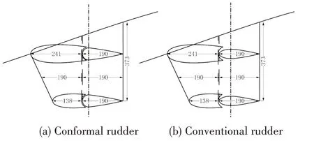
Fig.19 Size diagramof rudder models
3.3 Grid and conditions
The computational domain was a cylinder with a radius ofLsand a total length of 4Ls.The distance from the inlet to the bow wasLs,and from outlet to stern was 2Ls.And the inlet velocity was set as 0.In order to carry out the numerical uncertainty analysis,three sets of grids were generated by using the uniform refinement ratio 2 in all the directions of the grid,and the number of grids was 1.35×106,3.74×106,9.72×106respectively.Fig.20 shows the mesh distribution of the medium mesh on the symmetry plane.The bow,the fairwater,the stern appendages and the wake area were refined.The details of rudder mesh are shown in Fig.21.

Fig.20 Profile meshes of computational domain

Fig.21 Details of rudder mesh
3.4 Uncertainty analysis of numerical simulation
The uncertainty analysisconsistsof verification and validation.Verification isdefined as a process for assessing numerical simulation uncertaintyUSN.The RANSused in the present paper is an unsteady simulation method,thus the simulation uncertaintyUSNis composed of grid uncertaintyUG,iterative uncertaintyUI,and time step uncertaintyUT.When the solution is completely converged,the iterative uncertainty is often negligible,that is,U2SN-U2G-U2T.Validation is defined as a process for assessing modeling uncertaintyUSMusing benchmark experimental data.
No experimental data are available for the maneuvering in the submarine vertical plane.Anyhow,the verification of numerical simulation was carried out according to Ref.[16].
To assess theUG,three sets of grids as described above were used with the time step(Δt)of 0.2 s.And three different time steps were used for the medium grid simulation to assess theUT.The uncertainty of grid and time step is shown in Tab.3.And the definition of diving-surfacing angle()χis shown in Fig.22.TheUSNis lower than 5%.In the latter simulation,the medium grid andΔt=0.2 sare used.

Fig.22 Definitions of diving-surfacing angle and trim angle

Tab.3 Uncertainty of diving-surfacing angle
3.5 Comparison of maneuvering in the vertical plane
The simulation of maneuvering in the vertical plane ischaracterized by two phases:
(1)Acceleration and stabilization The propeller accelerates the submarine model from standstill to a predetermined speed,i.e.,Fr=0.11,and then maintains this speed.The rudder angle remains five degrees from the start of the simulation.In order to prevent the onset of non-zero trim angle and heave velocity at the start of the maneuver,only the longitudinal motion is switched on in thisphase.
(2)Free running After the motion has remained stable for a while,switch on the heave and trim motion.A 3 DOF simulation is carried out.Before releasing the trim and heave freedom,the pitching moment generated by the rudder has already acted on the submarine,rather than slowly loading with the rotation of the rudder as with the actual situation.Therefore,the submarine will have an oscillation after being released,which should be slighter in the actual situation.However,the state and speed of the submarine after entering a stable surfacing state should not be affected by the oscillation.
Fig.23 illustrates the submarine response in terms of trajectory and kinematics.The submarines with three different types of rudders have the same motion law after release.The diving-surfacing angle(χ)and the trim angle(θ)reach a steady state after fluctuation.The submarine equipped with the conventional rudder has the lowestχandθin the steady stage.And the conformal rudder and gap-sealed conformal rudder could increase theχandθby about 65%and 105%respectively,as can be seen in Tab.4.

Fig.23 Submarine response in terms of trajectory and kinematics
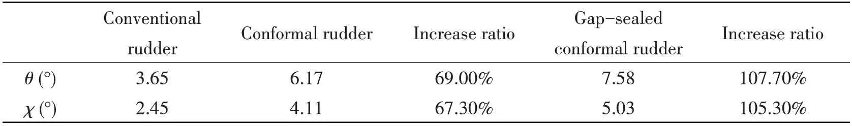
Tab.4 Efficiency of different rudder configurationson the maneuver
In general,the improvement in the vertical plane maneuverability of the submarine by using the conformal rudder issignificant.
The flow fields around the rudders are shown in Fig.24.The conventional rudder has an obvious eddy current between the rotatable rudder and the fin,and the flow separation phenomenon can be observed at the tail.Since the rotatable rudder and the fin of the conformal rudder form a complete airfoil,there will be no eddy current between the rudder and fin,and the flow separation is also weaker.Therefore,the rudder force can be improved.As for the gap-sealed conformal rudder,the flow from the pressure surface to the suction surface in the gap is prevented,so that the flow separation is suppressed,and the rudder force can be further improved.

Fig.24 Flow field around the rudder
4 Conclusions
In this paper,the open water hydrodynamic characteristics of conformal rudders were studied through water tunnel experiment and CFD.The maneuvering in the vertical plane of the submarine equipped with a conventional rudder,a conformal rudder and a gap-sealed conformal rudder respectively were studied through CFD.The results were summarized as follows:
(1)The conformal rudder has a critical angle,and theCLcurve is linear within the critical angle.The slope decreases when the critical angle is exceeded.This phenomenon is caused by flow separation on the suction side of the rudder.
(2)Both the increase of theReand sealing of the gap between the rudder and the fin can effectively improve the hydrodynamic performance by increasing the critical angle.
(3)CLincreases with chord ratio and aspect ratio.CTalso increases with the chord ratio.Increase of the aspect ratio can reduce the critical angle.
(4)The conformal rudder can significantly improve the vertical plane maneuverability of the submarine.
杂志排行
船舶力学的其它文章
- Application of the Cell-vertex Finite Volume Method in the Solution of the Lubrication Characteristicsof Journal Bearings
- Numerical Simulations on the Dynamic Characteristicsof a Shallow-draft Spar-type Floating Wind Turbine
- Study on Torque Characteristics and Structural Strength of Large Container Shipsunder Oblique Waves
- Collapse Analysis of Model Sphere of Titanium Manned Cabin under External Pressure
- Numerical Investigation of Dynamic Responsesof Ship Structure and Gas Turbine Subjected to Underwater Explosion
- Study on the Performance of Micro-perforated Plate Absorber under Coupling