Poly caprolactone/titanium dioxide nanofibe coating on AM50 alloy for biomedical application
2021-05-21MniKrthegMognPrneshChocklingmPoongothiNgrjnSrinivsn
Mni Krtheg, Mogn Prnesh, Chocklingm Poongothi, Ngrjn Srinivsn
a Department of Sciences, Amrita School of Engineering, Coimbatore, Amrita Vishwa, Vidyapeetham, India
b Department of Chemistry, Manonmaniam Sundaranar University, Tirunelveli, India
Received 12 March 2020; received in revised form 24 May 2020; accepted 8 July 2020
Available online 14 August 2020
Abstract
Keywords: Electrospinning; AM50 alloy; Polycaprolactone; Biocompatible; Corrosion resistance; Electrochemical studies.
1. Introduction
In recent years, magnesium (Mg) and its alloys have attracted much attention especially for high load bearing applications, due to its favorable mechanical property, biocompatibility and biodegradability [1]. The biodegradable nature of Mg alloys prevents the need for second surgical procedure to remove the implanted material. But, application of Mg alloys as biodegradable implants is often hampered by its high degradation rate when placed inside the human body or when it comes in contact with SBF environment [2]. Hence, the rate of degradation has to be controlled to use Mg alloys as a long term implantable material. The reduction in the degradation rate of Mg alloy by controlling the metal ion release can be achieved by suitable surface modification Various surface modificatio techniques such as alloying, anodization, microarc oxidation, electrolytic oxidation, electrodeposition, sol-gel etc.,has been discussed and reported by several authors[3-7].Canceicao et al. [8] have reported the hydrofluori acid treatment followed by the polyacrylonitrile coating can control the degradation of Mg alloys. The micro-arc anodic oxidation in alkaline medium with and without addition of nanoparticles improves the corrosion protection of AM60B alloy was reported by Mandelli et al. [9]. Recent reports shows that coating of Mg surface with polymer either by dip coating or spray coating would reduce the release of Mg2+ions from Mg surface. Huang et al. [10] utilized dip coating method to prepare poly lactic acid coating on Mg substrate and reported that the surface modifie Mg surface yields the better corrosion resistance. Wong et al. [11] deposited PCL membrane on AZ91 alloy, which controlled the release of Mg2+ions resulting in the reduction in the corrosion rate.
In addition to the various surface coating methods, electrospinning technique is gaining much interest in surface modificatio of Mg alloys due to their unique properties.It can produce polymeric fiber in nanoscale and deposit over metallic substrates [12,13]. The choice of polymeric material for electrospinning is decided by its properties such as biocompatibility, limited toxicity, biodegradability and sufficien mechanical properties. The polymer used for electrospinning coating should also have some functionalities to stimulate the precipitation of apatite like compounds during bone formation [14]. In recent time, significan advancement in the development of composite materials with structural and material properties was obtained by combining synthetic polymer (polyvinyl alcohol (PVA), poly(lactic acid) (PLA),poly(lactide-coglycolide), polycaprolactone (PCL)) and natural polymers (keratin, chitosan, collagen, gelatin, hyaluronan,silk, alginate, fibrinoge and elastin) with ceramic particulate(silver, magnesium oxide, titanium di oxide, hydroxy apatite etc.) [15-17]. Hanas et al. [18] produced nano fibrou layer on AZ31 Mg alloy using electrospinning technique to control the degradation rate of Mg alloy in physiological medium.Jinwookim et al. [19] reported that PCL/ZnO coated by electrospinning technique over AZ31 Mg alloy showed good corrosion property and biocompatibility. Incorporation of graphene oxide/ silver nanoparticle into poly lactic acid nanofibe lead to the improvement of cytocompatability and antibacterial coating on Mg alloy [20]. Enhancement of biocompatibility, antibacterial activity and corrosion resistance was reported for poly lactic acid akermanite doxycycline electrospun nanofibrou coating on Mg alloy [21].
In the present study,we have used PCL which was reported to be more suitable polymer for scaffold application because of its biocompatibility and biodegradability. However, PCL in the present form is hydrophobic, which results in lack of wettability and poor cell adhesion [22]. Hence, PCL/TiO2composite coating was performed on AM50 alloy through electrospinning technique with the expectation that TiO2would contribute coating performance to reduce the degradation rate as well induce biological activity. Thus, composite nanofiber using PCL/TiO2were produced on AM50 alloy through electrospinning method. Various characterization such as SEM,EDAX, FTIR, electrochemical and cell culture was studied to understand the degradation rate and bioactivity.
2. Methods and materials
2.1. Chemicals and reagents
PCL and TiO2nanoparticles were purchased from Sigma Aldrich (for TiO2nanoparticles, no further characterization was carried out and we referred the data sheet provided by the company). All the other chemicals and reagents were analytical grade used as received.
2.2. Sample preparation
The specimen used for this study was AM50 alloy (obtained from Jagada Industries, Virudhunagar, India) with surface area 1cm2. The chemical composition of AM50 alloy is shown in Table 1. The surface of the specimen was polished using silicon carbide paper with grade ranging from 500 to 1200. Final polishing was done using alumina powder in order to obtain scratch free mirror finis surface. Then, it was washed thoroughly with water and degreased with acetone.

Table 1 Composition of AM50 alloy.
2.3. Solution preparation and electrospinning method
PCL solution was prepared by dissolving 0.8g of PCL(Mw=80,000g/mol) in 10ml of acetone for 3 h. (8wt% of PCL was taken after optimizing the electrospinning parameters such as voltage and concentration, through SEM analysis,which is not shown here). For PCL/TiO2composite solutions,2wt%, 4wt% and 6wt% of TiO2was added to PCL solution followed by vigorous stirring overnight at room temperature. Then, the solution was ultrasonicated for 1 h in room temperature. As prepared solution (PCL, PCL/2wt% TiO2,PCL/4wt% TiO2and PCL/ 6wt% TiO2) was taken in 5ml syringe and loaded into electrospinning instrument (ESPIN-Nano, Physics Equipments). High voltage of 20kV was applied between the syringe needle and AM50 alloy acted as a collector.In turn the collector was grounded.The distance between the needle and collector was maintained around 15cm and fl w rate was adjusted to 4ml/h.
2.4. Surface characterization
Surface morphology and elemental composition of the nanofiber produced on AM50 alloy using electrospinning technique was analysed by Field Emission Scanning Electron Microscope (Fe- SEM ZEISS Scanning Electron Microscope- Sigma V) equipped with Energy Dispersive X-ray analysis. The average fibe diameter for 200 fiber electrospun on each specimen was measured using Image J software. The crystallographic structures of PCL and PCL/TiO2electrospun on AM50 alloy was analysed by X- ray Diffraction Patterns recorded by Pan analytical XPert Pro diffractometer using Cu Kα radiation in the range 2θ=10°- 90° with the scan rate of 0.02°.The wavelength of X-ray used was 1.54 °A with applied voltage and current in the order of 40kV and 25mA. FTIR studies of AM50 alloy coated with PCL and PCL/TiO2was studied using Thermo Scientifi (USA model: Nicolet iS10)in the range 4000 cm-1to 400 cm-1.
2.5. Electrochemical characterization
The electrochemical measurements were carried out using three electrode fla cell assembly maintained at room temperature. It consists of three electrodes, namely, saturated calomel electrode (SCE), platinum and AM50 alloy as reference, counter and working electrode respectively. The electrolyte used was SBF solution. The SBF solution was maintained at 7.4pH. The preparation of SBF solution and the procedure for conducting electrochemical experiments were carried out using earlier reports[23].Corrosion measurements were carried for each specimen in SBF solution using ZIVE SP1, controlled through a personnel computer. OCP studies for the specimen immersed in SBF solution was noted for 100 s. The potentiodynamic polarization was carried out with a scan rate of 10 m Vs-1. EIS measurements were done with the frequency range varying from 104Hz to 10-1Hz. The amplitude of the superimposed a.c signal was 10mV peak to peak voltage. The data obtained in terms of bode phase angle and impedance plot was interpreted and fitte using nonlinear least square method. For reproducibility of the results,experiments were repeated thrice.
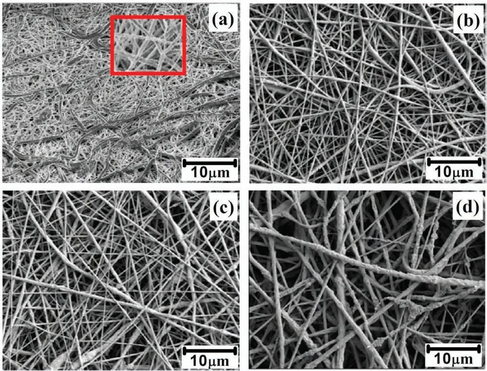
Fig. 1. SEM images of (a). PCL (b). PCL/2wt% TiO2 (c). PCL/4wt% TiO2 and (d). PCL/6wt% TiO2 coated on AM50 alloy.
2.6. Cell culture studies
Cell culture studies were carried out for AM50 alloy coated with PCL and PCL/6wt% TiO2. The L929 cells were grown in minimum essential medium (MEM) supplemented with 10% fetal bovine serum (FBS). The cells were deprived of serum for 8 hour before the adhesion assay. To do so, cells were washed three times with serum-free MEM and then grown in MEM. Trypsin & Versene was used to detach the cells and then it was observed under a microscope to confir complete dissociation of the cells, which would take approximately 10 min. Then the cells were washed twice with MEM to remove ethylene diamine tetra acetic acid (EDTA).The cells were seeded at a density 5×10⁴cells/ml. For cellsubstratum adhesion assay,10 μl cell suspension was added to the sample wells. The plates were incubated at 37°C for 48 h to allow the cells to adhere to the surface. Then 100 μl MEM was added to each well to wash off any non-adherent cells.Later, it was washed for four times. In order to achieve consistency, MEM was added/removed gently with multi-channel pipette for multiple wells. After washing, DMEM with 10%FBS was added and incubated the cells at 37°C for 4 h for recovery.
3. Results and discussion
3.1. Morphology and structural characterization of electrospun AM50 alloy
Fig. 1 shows the SEM images of the electrospinningly developed PCL and PCL/ TiO2composites nanofibe coated AM50 alloy. Fig. 1(a) depicts the surface morphology of the PCL coated AM50 alloy. It was observed that the morphology appears to be fibers uniform and regular without any beads. Fig. 1(a) (inset) shows the fiber are hollow with ribbon like structure, this might be due to the solvent trapped inside the fiber were rapidly evaporated creating a hollow structure.This structure collapsed under the atmospheric pressure to form ribbon like shape [24]. Fig. 1(b) and (c) shows the fiber are highly aligned, randomly oriented, smooth and continuous with regular geometry. Also, we can clearly observe that the fiber are densely packed. This may be due to the size of TiO2particle, which are well incorporated within the fibe. The feasibility and incorporation of nanoparticles into the fiber has been confirme in the previous reports [25]. PCL/6wt% TiO2coated AM50 alloy is shown in Fig. 1(d). A rough surface with number of protrusions could be observed. As the concentration of TiO2increased, most of the TiO2particles were well distributed within the fiber and some were located on the surface of the fiber forming protrusions. The dispersed TiO2had the tendency to accumulate at the center of the liquid to produce an elongation effect along the direction of the flui during its fligh in the air. This helped nanoparticles to settle inside the fiber rather on their surface [25,26].
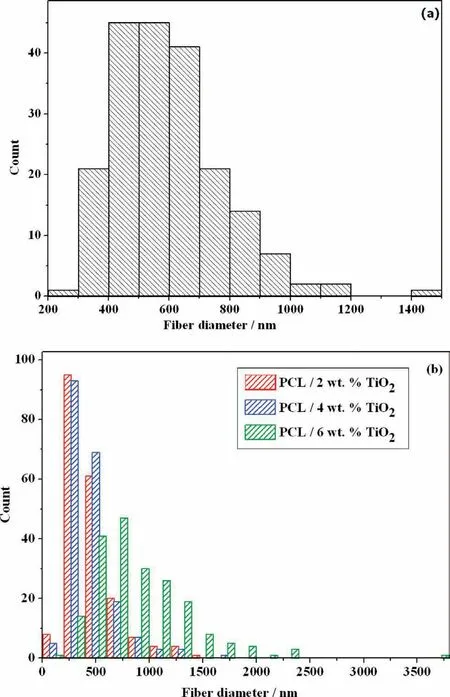
Fig. 2. Histogram of average fibe diameter of (a). PCL and (b). PCL/TiO2 (Various concentration) distributed on AM50 alloy.
The average fibe diameter of PCL and PCL/TiO2of various concentration electrospun over AM50 alloy is shown in Fig. 2. The average fibe diameter for PCL is in the range of 598nm. In case of PCL/2wt% TiO2and PCL/4wt% TiO2nanofibers the average fibe diameter was found by 460nm.The results indicate that the addition of TiO2in to PCL solution reduces the average diameter of nanofiber composite.The presence of TiO2causes high solution conductivity during electrospinning process which leads to the formation of lower fibe diameter, while further increasing the TiO2concentration to 6wt%, the average fibe diameter was found to be 901nm. This may be due to the increased viscosity of spinning solution which enabled the charged jet to withstand larger columbic repulsion. Also, it has been reported that the increased visco-elastic force also caused the onset for the bending instability to occur further away from the tip of the needle, causing the total path length that a jet segment traveled to the collector get decreased. The decreased path length caused the probability for the charged jet to be elongated by columbic repulsive force, making the fiber to increase in diameter with higher TiO2concentration [27]. In general the conductivity and viscosity of the polymeric solution plays an important role in determining the fibe diameter.
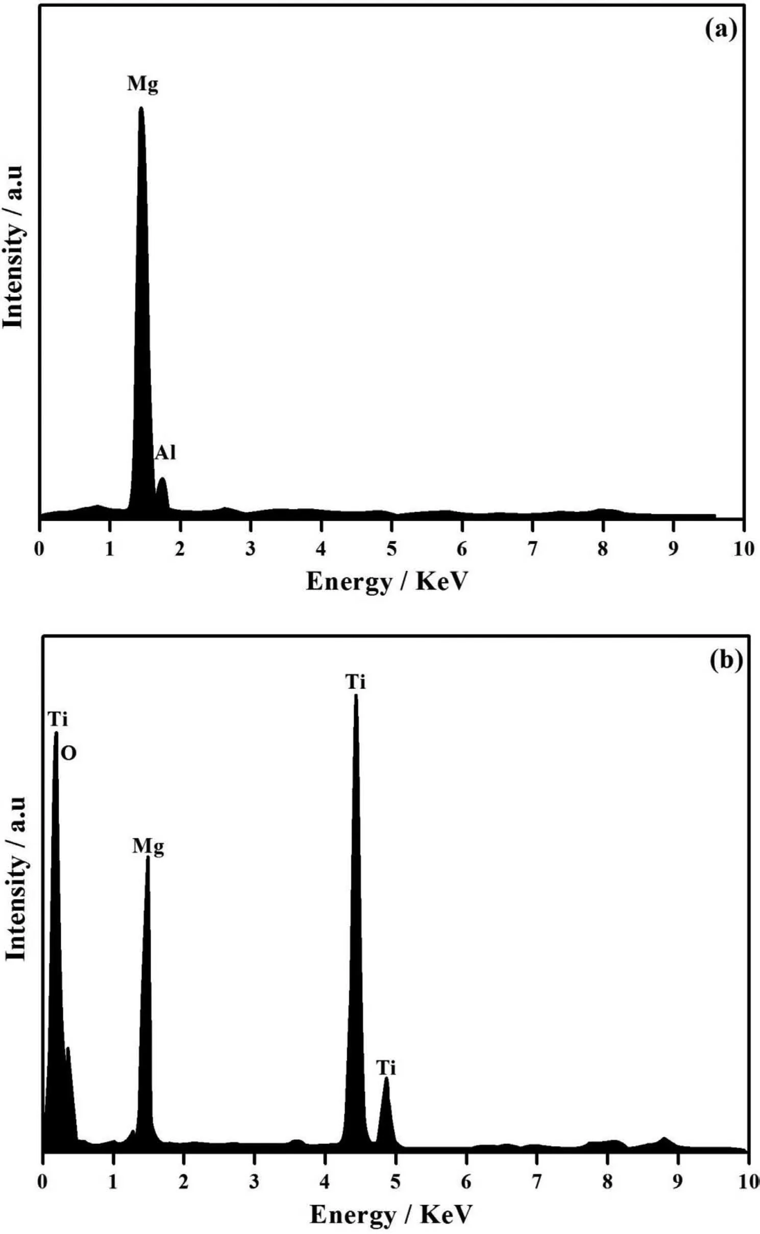
Fig. 3. EDAX spectra of (a). PCL and (b). PCL/6wt% TiO2 electrospun on AM50 alloy.
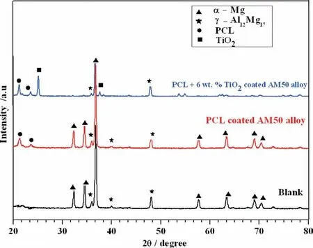
Fig. 4. XRD spectra of Blank, PCL and PCL/6wt% TiO2 electrospun on AM50 alloy.
Fig. 3 shows the EDAX analysis of PCL and PCL/TiO2electrospun over AM50 alloy. The EDAX peaks corresponding to Mg and Al are observed well along with their maximum peak intensity(Fig.3(a)).The peaks corresponding to Ti in Fig. 3(b) shows the incorporation of TiO2in PCL fibe. It has been reported that the TiO2nanoparticles are highly biocompatible, it can improve bioactivity and promote biomineralisation in the physicological medium [28]. This made us to study the behavior of higher concentration of TiO2i.e.,PCL/6wt% TiO2coated AM50 alloy and it was considered for further characterization. Moreover, in SEM images more number of TiO2particles found to be entrapped within the fibe which is clearly visible in Fig. 1(d).
The structural analysis of uncoated, PCL and PCL/6wt%TiO2electrospun AM50 alloy was studied using XRD and is shown in Fig. 4. The XRD peaks were identifie and indexed by comparing with standard JCPDS data (for Mg-JCPDS No 35-0821 and for Al JCPDS No- 04-0787). The peak at 2θ=32.3°, 34.36°, 38.34°, 57.70°, 63.32°, 69.1° and 70.57° corresponds to (100), (002), (101), (110), (103), (110)and (004) planes respectively [29]. A broad peak observed at 21.5° (110) and 23.8° (200) is due to amorphous nature of PCL [30], this confirm the presence of PCL fiber over AM50 alloy. Further, the peak corresponding to TiO2at 2θ=25.10° and 38.34° shows that TiO2nanofiber were coated over AM50 alloy [31].
FTIR analysis showed the variation in the spectral characteristics, which indicates the chemical bonding that might have occurred due to the blending of PCL with TiO2. FTIR spectra of PCL and PCL/6wt% TiO2coated AM50 alloy is shown in Fig. 5. The peak obtained at 2945 cm-1and 2865 cm-1attributed to the asymmetric and symmetric stretching of CH2respectively.The strong peak at 1730 cm-1is ascribed to the carbonyl group with C=O stretching. The typical band at 1370 cm-1indicates the presence of methylene C-H bending. The peaks at 1290 cm-1and 1240 cm-1corresponds to C-C stretching in the crystalline phase and C-O-C asymmetric stretching of PCL in amorphous phase at 1160 cm-1and 1040 cm-1corresponds to O-C vibrations [32]. The band appeared at 1000 cm-1is due to Ti-O and Ti-O-Ti vibrations[33].
3.2. Surface morphology and structural characterization of PCL and PCL/TiO2 coated AM50 alloy after immersion in SBF solution
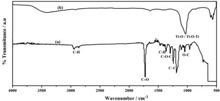
Fig. 5. FTIR spectra of (a). PCL and (b). PCL/6wt% TiO2 electrospun on AM50 alloy.
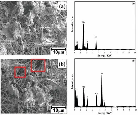
Fig. 6. SEM - EDAX images of (a). PCL and (b). PCL/6wt% TiO2 electrospun AM50 alloy on immersion in SBF solution.
In order to evaluate the bioactivity and biocompatibility of PCL and PCL/6wt% TiO2nanofibe coated AM50 alloy, immersion test were carried out in SBF solution for four days.The morphological variation of PCL and PCL/6wt% TiO2nanofibe coated AM50 alloy after immersion in SBF solution is shown in Fig. 6. SEM-EDAX analysis of PCL electrospun AM50 alloy immersed in SBF solution is shown in Fig. 6(a). SEM -EDAX analysis (Fig. 6(a)) represents that the fibrou structure of the PCL polymer retained even after four days of immersion in SBF solution, and also observed that there is a precipitation of some white colored particles on the surface of PCL electrospun AM50 alloy. These white particles can be the precipitation of calcium and phosphate ions which is present in the SBF solution. Fig. 6(b)shows the SEM - EDAX images of PCL/6wt% TiO2coated AM50 alloy immersed in SBF solution for 4 days. It was found that there is random formation of additional layer over the surface of the composite nanofibe . Interestingly, it was observed that in some regions there is a discontinuity or break in the nanofibers It can be attributed to the degradation of polymer in SBF solution. The degradation of PCL/6wt%TiO2on AM50 alloy was mainly concentrated in specifi sites which generally had some defects due to the irregular thickness produced by agglomeration of TiO2nanoparticles on the surface of the fibe, through which solution would have entered the fibe, creating discontinuity in the fibe morphology.
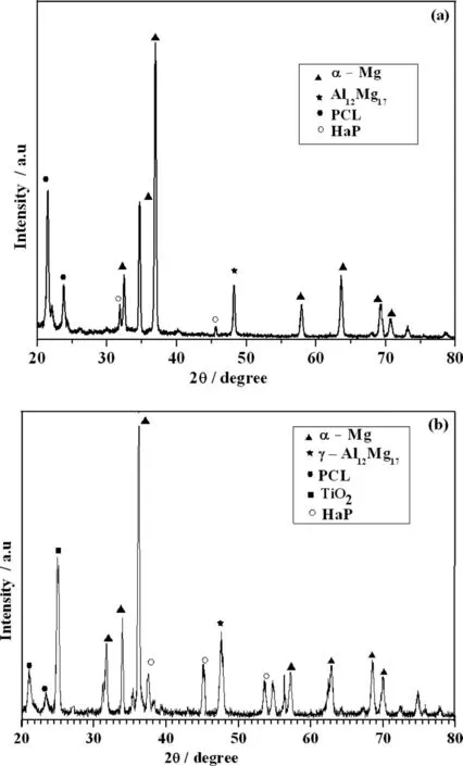
Fig. 7. XRD spectra of (a). PCL and (b). PCL/6wt% TiO2 electrospun AM50 alloy on immersion in SBF solution.
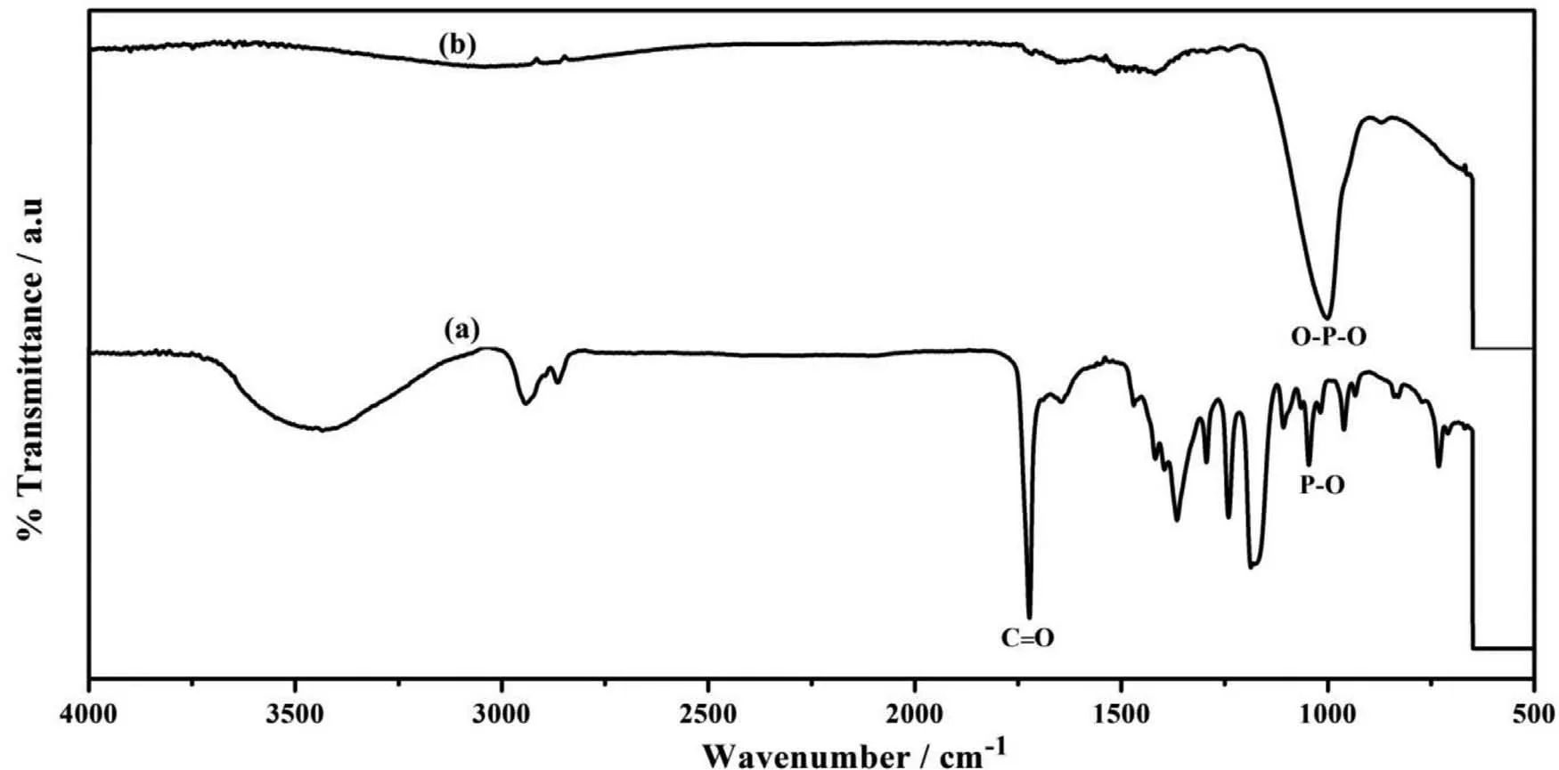
Fig. 8. FTIR spectra of (a). PCL and (b). PCL/6wt% TiO2 electrospun AM50 alloy on immersion in SBF solution.
The confirmatio of white colored particles and formation of additional layer over PCL and PCL/6wt% TiO2coated AM50 alloy immersed in SBF was done using EDAX analysis. The PCL and PCL/6wt% TiO2electrospun AM50 alloy shows the peaks corresponding to Ca and P, apart from Mg and Ti,which confirm the formation of CaP layer over AM50 alloy on both the specimen[34],which indicates that the electrospun coating over AM50 alloy exhibits good bioactivity.
Fig. 7 shows the XRD analysis of PCL and PCL/6wt%TiO2coated AM50 alloy immersed in SBF solution for 4 days. The XRD analysis of PCL electrospun AM50 alloy is shown in Fig. 7(a). Apart from peaks corresponding to Mg,Al and PCL, the peak at 2θ=31.90° and 46.71° corresponds to hydroxyapatite. The peaks present at 2θ=31.27°, 39.81°,45.14° and 53.69° also corresponds to hydroxyapatite, is very well observed for PCL/6wt% TiO2shown in Fig. 7(b) [35].
The presence of small peak intensity for PCL indicates that amount of calcium phosphate formed on the surface may be very less. This indicates that PCL exhibits low bioactivity compared to PCL/6wt% TiO2electrospun AM50 alloy.
Further, to understand the chemical bonding of PCL and PCL/6wt.% TiO2, in SBF solution for four days immersion,specimens were analysed by FTIR. Fig. 8. Showed the absorption bands at 400-600 cm-1which can be attributed to the doubly degenerated O-P-O bending mode of PO3-4 functional group.The peak at 1006 cm-1indicates the PO stretching vibration.The carbonyl group(C=O)stretching vibration peak appeared at 1729-1750 cm-1. This confirm the biomineralization of calcium phosphate [36]. Once the apatite nuclei are formed, they grow spontaneously by consuming the calcium and phosphate ions present in the solution.
3.3. Electrochemical studies
3.3.1. Potential time measurement
The corrosion behavior of PCL and PCL/6wt% TiO2coated on AM50 alloy in SBF solution can be measured by variation in corrosion potential with time. In general, this gives the information regarding the corrosion stability of coating over the surface of the specimen. Fig. 9 shows the open circuit potential curve (OCP) for PCL and PCL/6wt% TiO2electrospun AM50 alloy in SBF solution for various days of immersion.It is observed that the OCP values for PCL coated AM50 alloy is higher than that of PCL/6wt% TiO2nanofibe coated alloy and the corrosion potential value for both PCL and PCL/6wt% TiO2move towards more nobler values. This may be either due to the thickening of existing layer or due to the formation of corrosion product formed by the attack of Cl-ions present in SBF solution on AM50 alloy or nucleation of additional layer due to the ions present in the SBF solution. But from SEM-EDAX analysis (Fig. 6), we may conclude that the thickening happens because of the formation of calcium and phosphate ions present in the solution.The decrease in OCP value for PCL/6wt% TiO2on 4th day of immersion indicates either the degradation of polymer electrospunned on AM50 alloy or the substrate. Once the degradation of the substrate initiates,the bond strength between the coating and substrate tends to decrease, which further accelerates the coating degradation. Once the coating is destroyed,the coated specimen behaves like uncoated one. Zheludkevich et al. [37] reported that the sol-gel layer heavily loaded with ceramic particles can form a highly porous layer, which increases electrolyte uptake into the coating system (between metallic substrate and formed layer), causing low corrosion resistance and coating delamination.
3.3.2. Potentiodynamic polarization
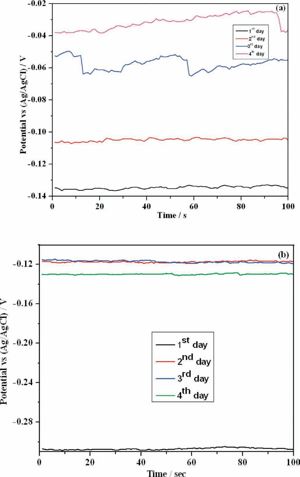
Fig. 9. OCP-time graph of (a). PCL and (b). PCL/6wt% TiO2 electrospun AM50 alloy on immersion in SBF solution.
The potentiodynamic polarization curves for uncoated,PCL and PCL/6wt% TiO2in SBF solution is presented in Fig. 10. The nature of the curve remains almost the same with a significan shift in potential towards positive direction for PCL and PCL/6wt% TiO2electrospun AM50 alloy compared to the uncoated specimen. Simultaneously, a decrease in current density around four orders of magnitude is observed for PCL electrospun AM50 alloy compared to that of PCL/6wt%TiO2electronspun AM50 alloy.This shows that PCL electrospun AM50 alloy exhibited higher corrosion resistance compared to other specimen. The increase in current density for PCL/6wt% TiO2electronspun AM50 alloy may be due to the higher concentration of TiO2nanoparticle which formed protrusion in the fibe morphology (as observed from SEM images) and in turn creating defects in the fibe through which easy diffusion of solution towards substrate would have taken place leading to initiation of corrosion process.
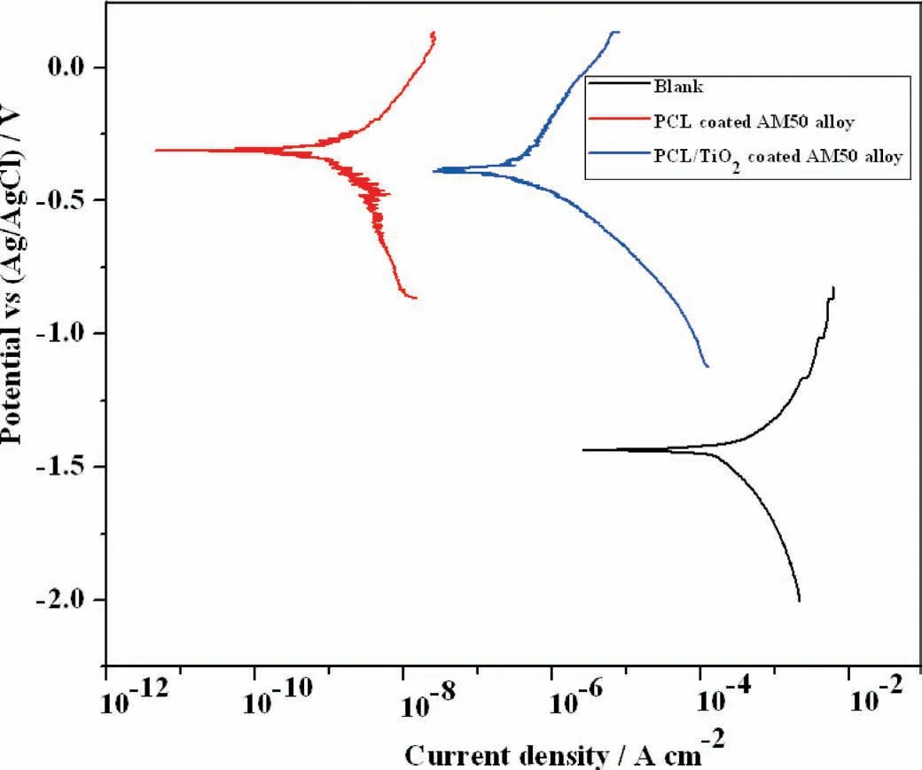
Fig. 10. Potentiodynamic polarization graph of blank, PCL and PCL/6wt% TiO2 electrospun AM50 alloy on immediate immersion in SBF solution.
3.3.3. Electrochemical impedance studies
The Bode phase angle plot for PCL and PCL/6wt% TiO2AM50 alloy in SBF solution is shown in Fig. 11. The Bode phase angle spectra for PCL electrospun AM50 alloy is represented in Fig.11(a).A capacitive behavior with two time constants could be observed. The two time constants are clearly indicated by two humps in phase angle spectra whose value is around -55° for both humps. Time constant between high and medium frequency range indicates the barrier oxide layer which might be due to Mg(OH)2. Whereas, the time constant between medium frequency and low frequency ranges depicts the nature of electrospun layer. It could be observed that nature of the spectra remained the same for all 4 days of immersion. The Bode phase angle spectra of PCL/6wt%TiO2is shown in Fig. 11(b). Here also, the presence of two time constants is very well seen in the spectra. The phase angle value at high frequency and low frequency region varied slightly for all 4 days of immersion. This indicates that electrospun layer act as a corrosion resistant layer preventing the degradation of polymer and alloy.At the same time,formation of nanofiber during electrospinning has large surface area to volume ratio,resulting in increased reaction between fibe and solution. As a result there must also be bio-mineralisation of calcium phosphate, which is very well seen in SEM image.But, the amount of CaP formed would be less for the instrument to deduct it, resulting in two time constant rather than three time constant as reported earlier in other articles [38].
Fig.12(a)shows the Bode impedance plot for PCL electrospun AM50 alloy immersed in SBF solution for 4 days. The impedance value increased with increase in immersion time for all the four days and at the same time for PCL/6wt%TiO2electrospun AM50 alloy, the impedance value increased till 3rd day (Fig. 12(b)). This indicates the formation of additional layer. This additional layer may be due to the exchange of ions present in the solution, resulting in the nucleation of calcium and phosphate over the surface of the alloy. This is very well corroborated with XRD and FTIR results. And on the 4th day, the impedance value decreased, indicating the initiation of the corrosion process and the polymer degradation.
The process involved in degradation of AM50 alloy in SBF solution is been discussed below and it is schematic representation is shown in Fig.13.The redox reactions responsible for the overall corrosion process of Mg alloys are listed below
Cathodic reactions:
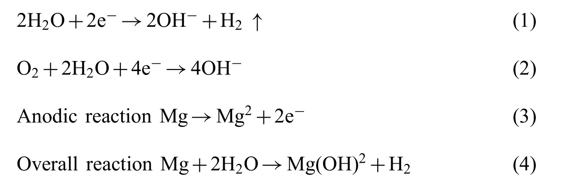
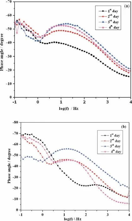
Fig. 11. Bode phase angle plot of (a). PCL and (b).PCL/6wt% TiO2 electrospun AM50 alloy on immersion in SBF solution.
As indicated by Eq.(4),the main products of the corrosion reaction are hydrogen gas and insoluble magnesium hydroxide. The local conditions may also promote the formation of hydroxides of the alloying elements and hydrated oxides [39].
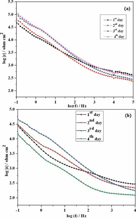
Fig. 12. Bode impedance plot of (a). PCL and (b). PCL/6wt% TiO2 electrospun AM50 alloy on immersion in SBF solution.
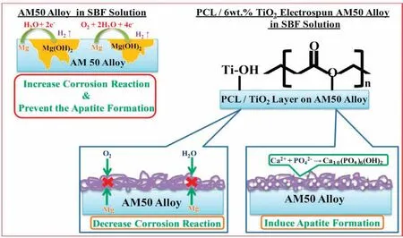
Fig. 13. Corrosion mechanism for PCL/6wt% TiO2 electrospun AM50 alloy on immersion in SBF solution.
The main role of the coating is to hinder water and oxygen to reach the Mg substrate and slow down the corrosion rate at early stages of immersion. This is possible due to the formation of stable bonds between magnesium surface and polymer coating. The coating matrix is formed by dissolving PCL and TiO2in acetone which undergoes a nucleophillic substitution. This results in the formation of hydrogen bond(H+) between the carboxylic group of organic polymer (PCL)and the hydroxyl group (OH-) of inorganic matrix (TiO2).This layer is coated on AM50 alloy and is soaked in SBF solution [40]. The high content of TiO2in PCL/6wt% TiO2leads to increase of Ti-OH groups can stimulus the formation of apatite nucleation. Once the apatite nuclei formed, the growth occurs spontaneously consuming the positive ions of calcium and negative ions of phosphate from the SBF solution to form and transforms into hydroxyapatite. At the same time, the coating is still highly porous for PCL/6wt%TiO2,so, SBF solution is more likely to penetrate quite easily and contact the substrate leading corrosion attack.
The impedance spectra data obtained were fitte with an equivalent circuit. The equivalent circuit model Rs[(RbQb)(ResQes)] was used to fi the PCL and PCL/6wt%TiO2for 4 days of immersion is depicted in Fig. 14. Here in the circuit, Rsrepresents the solution resistance, Resand Qesrepresents the resistance and capacitance of the electrospun layer, and Rband Qbrepresents the resistance and capacitance offered by the barrier layer. The resistance and capacitance values determined by fittin the spectra with an equivalent circuit for both the specimen are presented in Table 2. It is observed that the resistance of the electrospun layer increased and the capacitance value get decreased with immersion time for PCL electrospun AM50 alloy, whereas for PCL/6wt% TiO2the resistance of electrospun layer decreased. This showed that PCL electrospun AM50 alloy exhibited better corrosion resistance and also stability of the polymer fil retained in SBF solution. Further at the same time, the barrier resistance fluctuate for all the four days, indicating the subsequent initiation and formation of the corrosion product for PCL. Even this might have also acted as corrosion protection layer, because as observed from OCP value and impedance plot, the potential and impedance value continuously increased with immersion time. But for PCL/6wt%TiO2electrospun AM50 alloy, the barrier layer resistance decreased. This indicates slow degradation of the polymer over the substrate. The capacitance value of the barrier layer depends on the surface area of the active pores formed due to agglomeration of TiO2particles, which is been fille with solution. Thus increase in immersion time in SBF solution would have activated more pores in the polymeric coating.This shows that at higher concentration of TiO2, particle agglomeration occurs, resulting in a reduction of the protective performance of the coating mainly because of creating uneven surface. This makes us to conclude that by controlling the concentration of TiO2particles in the coating it is possible to slow down or accelerate the corrosion resistance while maintaining the necessary biocompatibility [41].
3.4. Cell culture studies
The cytocompatibility and bioactivity of a biomaterial are strongly dependent on its surface properties, because any biological reactions occur firs directly on its surface when it is contact with biological environment [12]. To understand the ability of PCL and PCL/6wt% TiO2electrospun AM50 alloy to support fibroblas proliferations, L929 cells were seeded and cultured for 48 h. Fig. 15 shows the SEM images of growth of cell cultured on PCL and PCL/6wt% TiO2coated AM50 alloy. Significan differences were observed between both the specimens. The amount of cell distributed on PCL electrospun AM50 alloy was less compared to the PCL/6wt%TiO2electrospun AM50 alloy. In case of PCL/6wt% TiO2coated AM50 alloy, uniform distribution of cells within the entire fibe can be observed. Also, discontinuity in the fibe was observed within 48 h of immersion of the specimen in cell culture medium. This is in correlation with the results obtained from the SEM image (Fig. 6(b)).
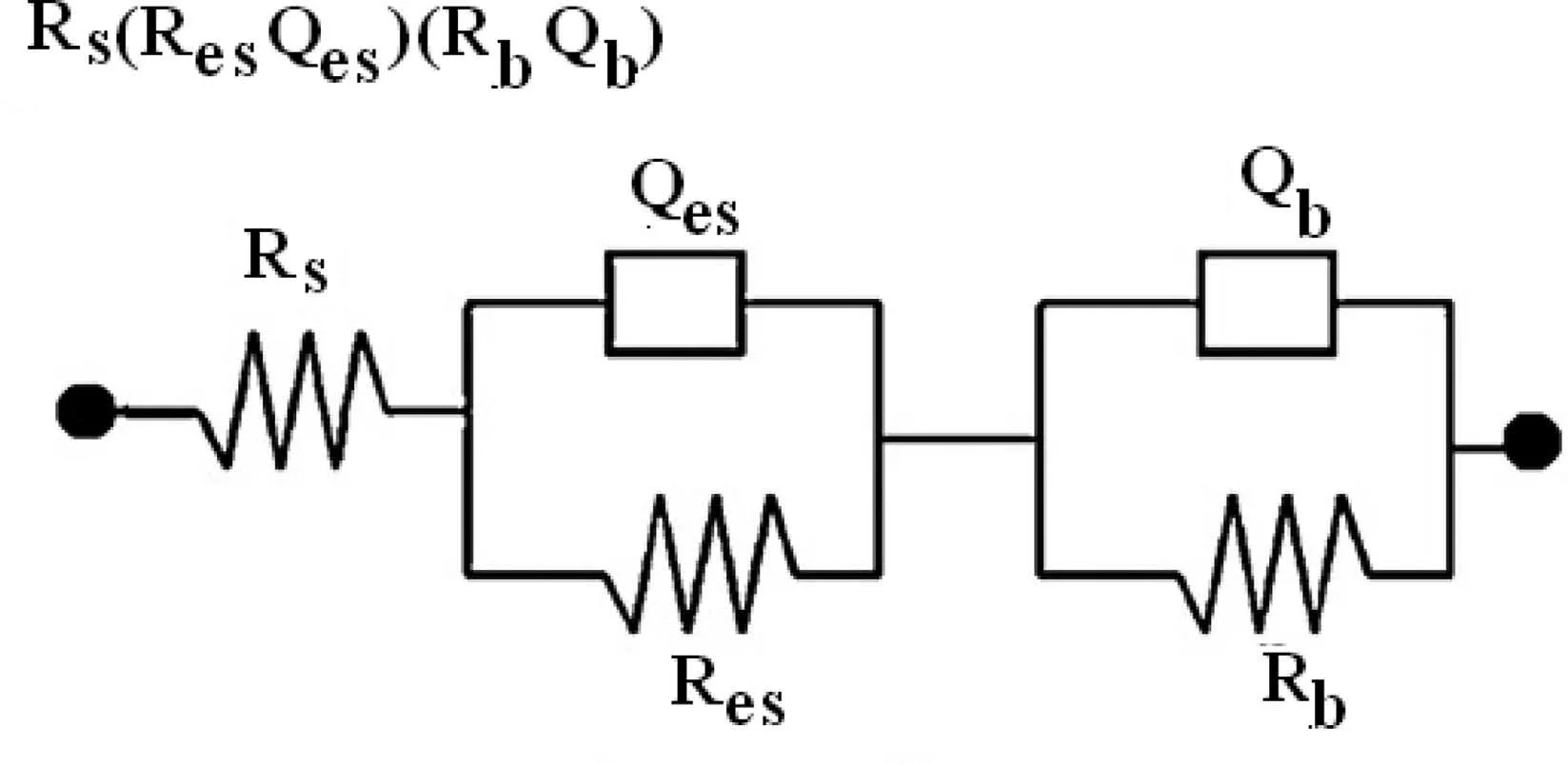
Fig. 14. Equivalent circuit model for PCL and PCL/6wt% TiO2 electrospun AM50 alloy on immersion in SBF solution.
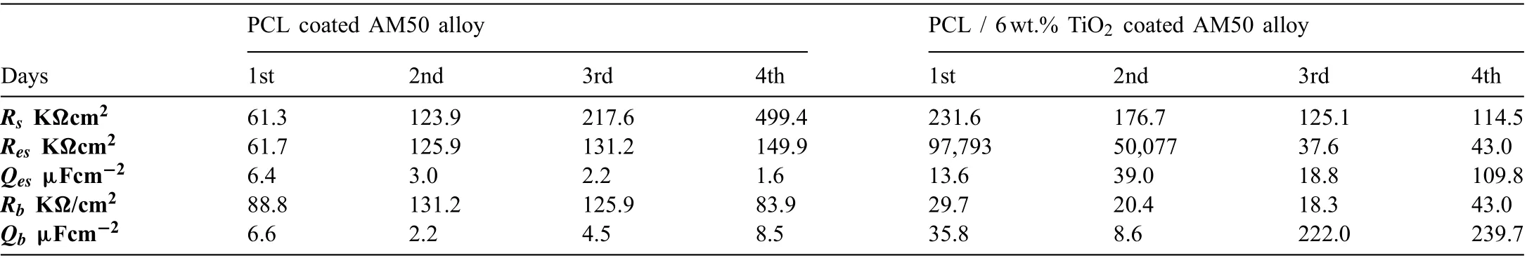
Table 2 Fitted values of the spectra of PCL and PCL/6wt.% TiO2 coated AM50 alloy.
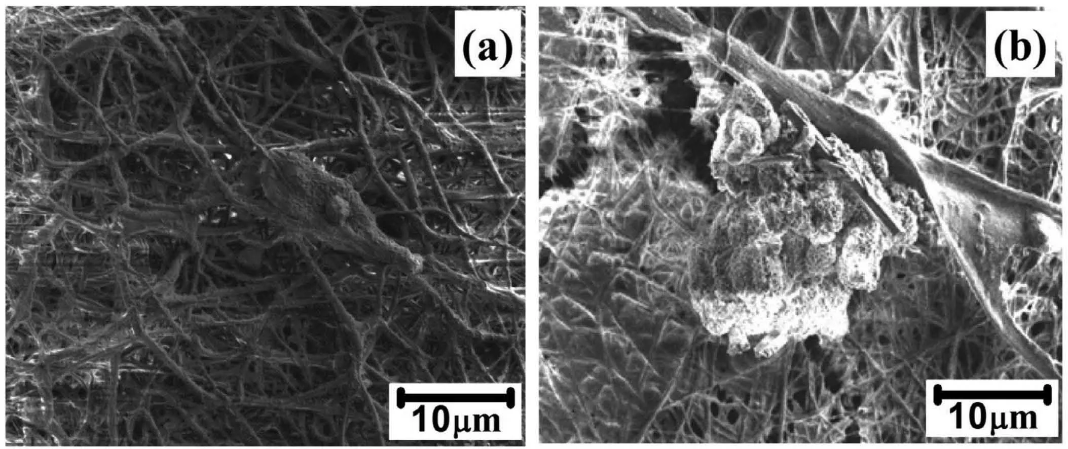
Fig. 15. Cell culture studies of (a). PCL and PCL 6wt% TiO2 electrospun AM50 alloy on immersion in SBF solution.
4. Conclusion
The present study concluded the formation of nanofibrou PCL and PCL/TiO2composite coating on AM50 alloy using electrospinning technique. Uniform and hollow fiber were obtained for PCL electrospun AM50 alloy. A rough and thicker fiber were observed for PCL/6wt% TiO2electrospun AM50 alloy due to agglomeration of TiO2nanoparticles. The electrochemical corrosion studies in SBF solution confirme that the PCL coating exhibited higher corrosion resistance than PCL/6wt%TiO2composites and uncoated alloy.The formation of hydroxyl apatite or deposition of calcium and phosphate has proved the bioactivity and biocompatibility of PCL and PCL/6wt% TiO2nanofibe over AM50 alloy.The cell culture studies reveals that the composite nanofi brous coatings, shows drastic and enhanced cell adhesion and growth, which might be due to the presence of biocompatible TiO2nanoparticle.
Conflict of Interest Statement
The authors whose names are listed immediately below certify that they have NO affiliation with or involvement in any organization or entity with any financia or non-financia interest in the subject matter or materials discussed in this manuscript.
Acknowledgment
One of the authors, M. Karthega thank the Department of Sciences and Technology(DST),New Delhi for their financia assistance (Sanctioned vide order No. SR/FTP/ETA-031/2012 dt 21.12.2012).One of the author Nagarajan Srinivasan would like to acknowledge Department of Biotechnology (DBT),Government of India for support through Ramalingaswami Re-entry Fellowship (BT/RLF/Re-entry/40/2015)
杂志排行

Journal of Magnesium and Alloys的其它文章
- Mechanism of Mn on inhibiting Fe-caused magnesium corrosion
- Investigating TiO2-HA-PCL hybrid coating as an efficien corrosion resistant barrier of ZM21 Mg alloy✩
- Effect of yttrium modificatio on the corrosion behavior of AZ63 magnesium alloy in sodium chloride solution
- Effect of lithium content on the mechanical and corrosion behaviors of HCP binary Mg-Li alloys
- New design principles for the bath towards chromate- and crack-free conversion coatings on magnesium alloys
- Pore characterization of PM Mg-0.6Ca alloy and its degradation behavior under physiological conditions