Distributed Secondary Control of AC Microgrids With External Disturbances and Directed Communication Topologies: A Full-Order Sliding-Mode Approach
2021-04-16BodaNingMemberIEEEQingLongHanFellowIEEEandLeiDingMemberIEEE
Boda Ning, Member, IEEE, Qing-Long Han, Fellow, IEEE, and Lei Ding, Member, IEEE
Abstract—This paper addresses the problem of distributed secondary control for islanded AC microgrids with external disturbances.By using a full-order sliding-mode(FOSM)approach,voltage regulation and frequency restoration are achieved in finite time. For voltage regulation, a distributed observer is proposed for each distributed generator (DG) to estimate a reference voltage level. Different from some conventional observers, the reference voltage level in this paper is accurately estimated under directed communication topologies.Based on the observer,a new nonlinear controller is designed in a backstepping manner such that an FOSM surface is reached in finite time. On the surface,the voltages of DGs are regulated to the reference level in finite time.For frequency restoration,a distributed controller is further proposed such that a constructed FOSM surface is reached in finite time, on which the frequencies of DGs are restored to a reference level in finite time under directed communication topologies. Finally, case studies on a modified IEEE 37-bus test system are conducted to demonstrate the effectiveness, the robustness against load changes,and the plug-and-play capability of the proposed controllers.
I. INTRODUCTION
MICROGRIDS have received intense research interest,offering the promise of complementing conventional power systems with advantages including high reliability, fast demand response, and sustainability [1]-[3]. A microgrid typically consists of distributed generators (DGs), energy storages [4], and loads [5]. Generally, microgrids can operate in a grid-connected mode or in an islanded mode due to the preplanned or unexpected scheduling. In this paper, we focus on the islanded mode, where the microgrid becomes disconnected from the main grid. One fundamental control object is to maintain frequencies and voltages of DGs to certain reference levels, and the so-called primary control based on each local DG controller is used to accomplish such a task.However, there are some deviations of frequencies and voltages from their reference levels due to the use of droop control.The so-called secondary control is then developed to compensate for the aforementioned deviations. In the existing literature, secondary control strategies of microgrids are mainly categorized into three types:centralized[6],decentralized [7],and distributed[8]-[13].For centralized approaches,a central processor is needed to collect information from all DGs and to send control commands back to each DG, leading to some undesirable issues such as heavy calculation costs and singlepoint failures. For decentralized approaches, it is difficult to realize efficient secondary control based solely on DG’s own information.Different from centralized and decentralized strategies, for distributed strategies, neighboring DG information exchange is allowed,thus reducing resources consumption and improving efficiency and reliability of microgrids. For example, in [10], a distributed averaging controller by using localized and neighboring information is proposed to collectively achieve secondary control in an infinite time horizon.Considering the convergence speed, a distributed finite-time controller is proposed in [12] to achieve voltage regulation and frequency restoration of DGs in finite time. In [14], a distributed finite-time controller is designed under switching topology. Compared with asymptotic stability convergence,the finite-time controller has advantages of fast convergence,high-precision of control performance, and robustness against disturbances [11]-[20].
Note that most of the existing distributed secondary controllers are proposed based on an assumption that external disturbances do not affect the dynamics of DGs. In practice,however, it is inevitable that DG units suffer from some timevarying or unknown external disturbances [21]. The external disturbances can degrade or even destroy micorgrid stability if no action is taken. In the literature, sliding-mode control is a typical strategy to maintain system robustness against external disturbances by using a discontinuous control signal and forcing the system to slide along a predefined switching surface [22]-[27].Conventionally,a sliding-mode surface is constructed such that the surface has desirable reducedorder dynamics when constrained to it, i.e., the ideal slidingmode motion is of reduced-order [22]. Instead, a full-order sliding-mode (FOSM) surface is proposed in [28], and a chattering free controller is designed. During the reaching phase, the system evolves with desirable full-order dynamics.Following this line, consensus is achieved for second-order multi-agent systems with either finite-time [29] or fixed-time convergence [30]. The FOSM design ensures that agent states are coupled on the sliding-mode surface, while the slidingmode states are decoupled from the surface. As a result,sliding-mode controllers can be designed independently,which leaves room for the consensus controller design for complex networked systems [29], [30]. In addition, the FOSM design can reduce the chattering phenomenon as demonstrated in[28].Although the FOSM approach has the aforementioned advantages, it has not been investigated in distributed secondary voltage regulation and frequency restoration mainly due to the difficulty caused by a reference signal, particularly when DGs are described by second-order dynamics.Besides external disturbances,most of the existing results of distributed secondary control are obtained under undirected communication topologies. In practice, directed (asymmetrical) interactions widely exist, e.g., two DGs cannot simultaneously exchange information if the equipped sensors have different communication ranges. Thus, it is necessary to design distributed secondary controllers under directed communication topologies.
From the aforementioned observation, in the presence of both external disturbances and directed communication topologies, it is a challenging issue how to develop new distributed finite-time secondary controllers for islanded microgrids such that voltage regulation and frequency restoration are achieved in finite time, which motivates the current study.
In this paper, we investigate distributed secondary voltage and frequency control for islanded microgrids by using an FOSM approach. The main contributions of this paper are stated as follows:
1) The problem of distributed secondary control for microgrids is formulated under a new scenario where external disturbances of DGs and directed communication topologies are taken into account;
2)For voltage regulation,a distributed observer is proposed for each DG to estimate a reference voltage level.Then,based on the observer, a new nonlinear controller is designed in a backstepping manner such that an FOSM surface is reached in finite time. On the surface, the voltages of DGs are regulated to the reference level in finite time;
3) For frequency restoration, a distributed FOSM surface is constructed, and a distributed controller is further proposed for each DG such that the surface is reached in finite time.The sliding-mode states are decoupled from the surface, on which the frequencies of DGs are restored to a reference level in finite time; and
4) Case studies with a modified IEEE 37-bus test system are provided to demonstrate the effectiveness, the robustness against load changes, and the plug-and-play capability of the proposed controllers.
II. PRELIMINARIES AND PROBLEM FORMULATION
A. Directed Communication

In addition, the information of reference levels for voltage and frequency can be treated as a command produced from a virtual leader, which can be communicated to only a few(but not all) DGs. Let ¯G be the directed communication graph among n DGs and one virtual leader. It is supposed that, the leader only sends out information and receives no information from any other DGs.When the ith DG has information access of the virtual leader,a notation biis set to be a positive number,and zero otherwise. Then, a matrix M is defined as M =Lf+B, where B =diag(b1,b2,...,bn). A directed path of a directed graph is denoted by a sequence of directed edges.The directed graph ¯G is said to contain a directed spanning tree if and only if there exists at least one DG that has a directed path to any other DGs.
B. Large-Signal Dynamics Model for AC Microgrids
In a microgrid, each DG unit consists of a DC source, a voltage-controlled voltage source inverter (VCVSI), an LC filter and an RL output connector. A block diagram shown in Fig.1 illustrates the control structure for DG i, i ∈Γ. In order to maintain the stability of frequency and voltage,droop control in the primary control layer is exploited for the ith DG by


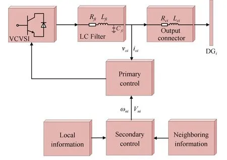
Fig.1. A control block diagram for inverter-based DG i.
Since the primary voltage control strategy aligns the output voltage magnitude of each DG on the d-axis of the corresponding reference frame [8], one further obtains


which indicates that the voltage control is equivalent to the goal of designing Vnisuch that the amplitude of each DG unit, vodi, is synchronized to a reference voltage level, vref.
Based on the work in [31]-[33], the nonlinear dynamics for the ith DG can be described in the form of

where xiis the state vector, and how to derive the detailed expressions for fi(xi),ki(xi),Di,gi(xi),hi(xi)are presented in Appendix A.
C. Problem Description and Preliminary
Based on the large-signal dynamics model of AC microgrids presented in Section II-B, two distributed secondary control problems are to be addressed.
The first problem is stated as: For the voltage control, ui=Vniand yi=vodiin (5), i ∈Γ, design a distributed controller to achieve finite-time voltage regulation, namely,

where T is upper bounded by a finite time T*.
The second problem is stated as: For the frequency control,ui= ωniand yi= ωiin (5), i ∈Γ, design a distributed controller to achieve finite-time frequency restoration,namely,where T is upper bounded by a finite time T**.

For distributed secondary control investigated in this paper, the controller design requires each DG’s own and its neighborhoods’information through a directed communication network. The following assumption is presented to facilitate the discussion of our main results in Section III.
Assumption 1: The directed graph ¯G contains a spanning tree with the virtual leader as the root.
III. MAIN RESULTS
In this section,we first propose a distributed observer based controller to achieve voltage regulation. Then, we design a distributed controller to achieve frequency restoration.
A. Distributed Finite-Time Secondary Voltage Control
In this subsection,we are dealing with the voltage regulation problem, i.e., ui=Vniand yi=vodiin (5), i ∈Γ. Note that the output vodiis not directly dependent on the input Vni[34],i.e., di= 0. In fact, Vniappears in the second derivative of vodi. Therefore, using the input-output feedback linearizion and taking the external disturbances into account [21], one obtains

and a set of internal dynamics of


Define an auxiliary controller as

Then, one obtains the following second-order dynamics


The aim becomes to design a proper εiin (9) to achieve finite-time voltage regulation. The design consists of three steps:
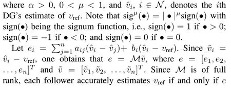
i) We first propose a distributed observer to estimate vrefin finite time. The observer is in the form of


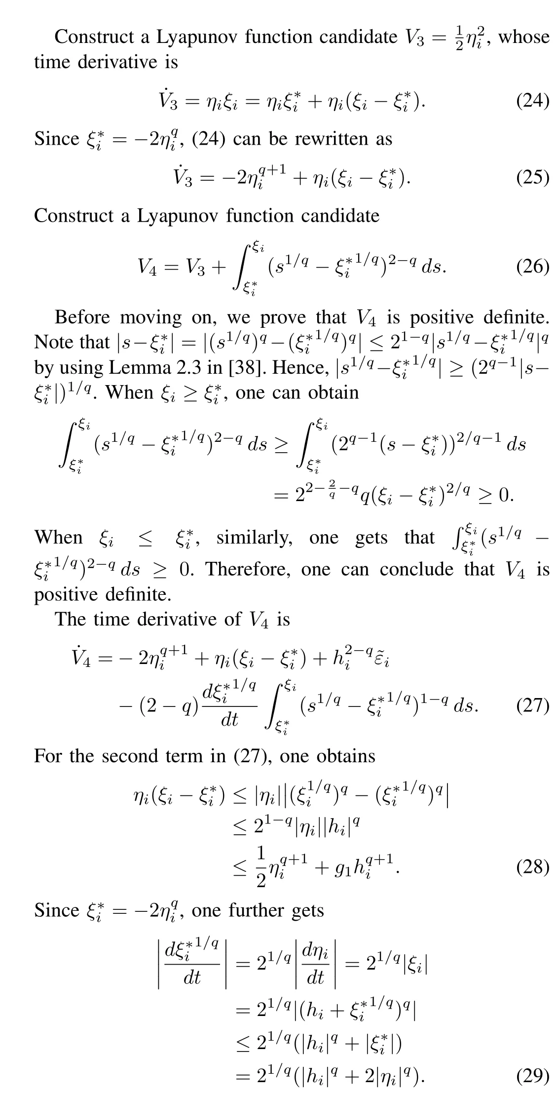
Then, for the last term in (27), one obtains

Therefore,

By using (17), one gets

Note that


From (32) and (34), it can be concluded that

By using Theorem 4.2 in [37], V4will converge to zero in a finite time of

The block diagram in Fig.2 shows the overall control structure for distributed finite-time voltage control.The results in this section are summarized in the following theorem.
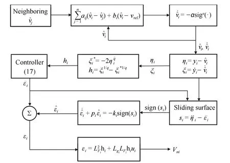
Fig.2. The block diagram of the secondary voltage control.
Theorem 1:Under Assumptions 1 and 2,for the system (9),by using controller (16)-(19) together with observer (10),distributed finite-time voltage regulation is achieved in finite time.
B. Distributed Finite-Time Secondary Frequency Control
In this section,we are dealing with the frequency restoration problem, i.e., ui= ωniand yi= ωiin (5), i ∈Γ. Note that the output ωiis directly dependent on the input ωni[34], i.e.,di/=0. Thus, using the input-output feedback linearizion and taking the external disturbances into account[21],one obtains

and a set of internal dynamics of


Following a similar approach in Section III-A, under Assumption 1, one gets

By using Theorem 4.2 in [37], V6will converge to zero in a finite time of

As a result, each DG accurately estimates the reference frequency in finite time.
The block diagram in Fig.3 shows the overall control structure for distributed finite-time frequency control. The results in this section are summarized in the following theorem.

Fig.3. The block diagram of the secondary frequency control.
Theorem 2: Under Assumptions 1 and 3, for the system (39), by using controller (40)-(42), distributed finitetime frequency restoration is achieved in finite time.
Remark 1: In controller (18) or (41), all terms are known except the term of sign(si) or sign(ςi) due to the external disturbance of φior ψi, respectively. To calculate sign(si),first define a function of

Then, sign(si) can be calculated by
sign(si)=sign(gi(t)-gi(t-τ)),
where τ is a time delay.Since si(t)=limτ→0+(gi(t)-gi(tτ))/τ, one can choose a fundamental sample time as τ in practice. Similarly, define a function of

Then, sign(ςi) can be calculated by
sign(ςi)=sign(zi(t)-zi(t-τ)).
From the above analysis, it can be seen that the exact value of sior ςiis not needed. Instead, we only need to determine whether gi(t) or zi(t) is increasing or decreasing.
IV. CASE STUDIES
In this section, case studies are carried out on a modified IEEE 37-bus test system [39], which is shown in Fig.4. The test system has six DGs (i.e., n = 6), among which the communication topology is shown in Fig.5. The information of reference levels for frequency (50 Hz) and voltage (380 V)is available to DG 5. The parameters of DGs and loads are summarized in Table I, and line parameters are provided in [39]. The case studies are conducted in the Matlab/PSAT environment.
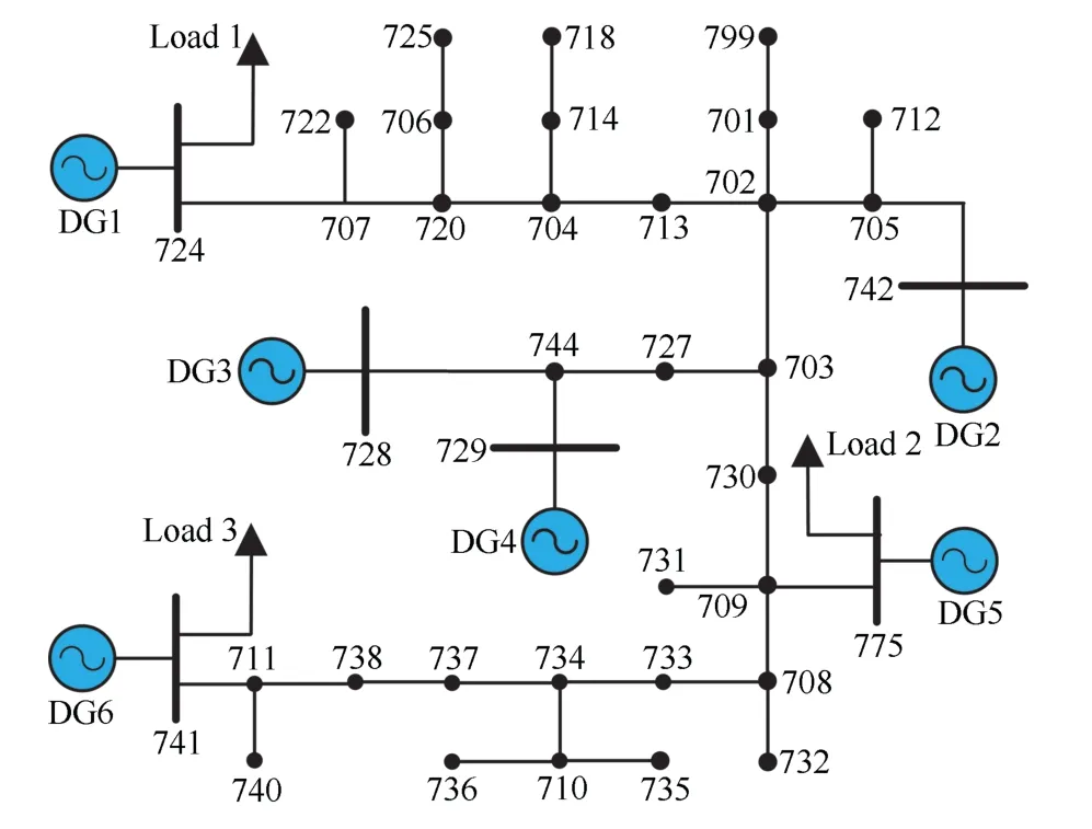
Fig.4. The modified IEEE 37 bus test feeder.

Fig.5. Directed communication topology among DGs for Case Studies (i),(iii), and (iv).

TABLE I PARAMETERS FOR DGS AND LOADS
A. Case Study (i): Performance Evaluation
We focus on the period after the primary control, and treat t = 0 s as the starting point of the secondary control.At t = 0 s, the test system is initialized with ω1(0) =ω2(0) = ω3(0) = ω4(0) = ω5(0) = ω6(0) = 49.2 Hz;vod1(0) = 377.2 V, vod2(0) = 376.9 V, vod3(0) = 374.5 V,vod4(0) = 373.2 V, vod5(0) = 378.2 V, vod6(0) = 379.1 V.The external disturbances are described by ψi= 0.2sin(2πt)and φi=0.3cos(2πt). The controller parameters are selected as: α =5, μ=2/3, q =3/5. Implementing controller (16)-(19) together with observer (10), and controller (40)-(42),for n = 6, results are shown in Fig.6. Voltage regulation and frequency restoration are achieved at t = 3.1 s and t = 0.6 s, respectively. To make a comparison, we further implement the controller proposed in Section V of [21]. The corresponding result is presented in the first plot of Fig.7,where convergence is not achieved due to the presence of external disturbances. Then, combining the controller in [21]with the FOSM approach, the result is shown in the second plot of Fig.7, where the frequency restoration is achieved at t=0.8 s, longer than that in the fourth plot of Fig.6.

Fig.6. Case Study (i)-The two auxiliary variables ξi, ηi, voltage amplitude vodi, frequency ωi, respectively.
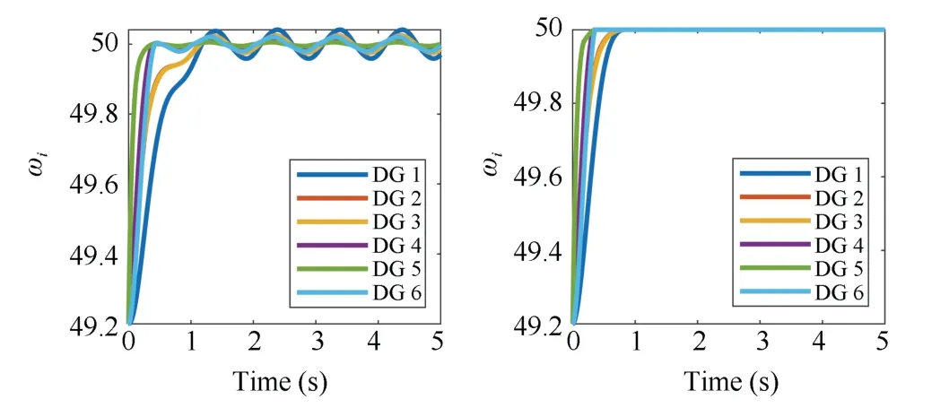
Fig.7. Case Study (i)-Results using the controller in [21].
B. Case Study (ii): Communication Topology Changes
In a microgrid,communication topology can vary according to different communication limitation,e.g.,change from Fig.5 to Fig.8.Therefore,it is necessary to validate the performance of the proposed controllers with the changed topology. The controller parameters are selected the same as that in Study (i).With the changed topology shown in Fig.8, for n = 6,implementing controller (16)-(19) together with observer(10), and controller (40)-(42), results are shown in Fig.9.Voltage regulation and frequency restoration are achieved at t = 3.5 s and t = 0.7 s, respectively. It is demonstrated that the proposed controllers are effective with topology change.It should be pointed out that the topology changes only once in the simulation,which is different from the switching topology case in [40].

Fig.8. Directed communication topology among DGs for Case Study (ii).
C. Case Study (iii): Load Changes
In a microgrid, loads can vary according to different requirement at a specific time. Therefore, it is necessary to validate the robustness of the proposed controllers against load changes. In this case, it is assumed that Load 3 is doubled at t = 5 s. The controller parameters are selected as: α = 4, μ = 13/15, q = 3/5. Implementing controller(16)-(19) together with observer (10), and controller (40)-(42), for n = 6, the impact of load changes is shown in Fig.10. It is observed that, at t = 5 s, the voltage amplitude and the frequency of DGs are suffering from some deviations caused by the change of Load 2, then the voltage amplitude is restored within 3.2 s, and the frequency is restored within 0.6 s. Therefore, the proposed controller is robust against load changes.
D. Case Study (iv): Plug-and-Play Capability
The Plug-and-Play capability is essential for a microgrid due to the intermittent nature of DGs. In other words, when some DGs are added into or removed from the microgrid,the proposed controllers are still able to work effectively to guarantee the normal system operation. To address this concern, it is assumed that a “DG 7” is added to Bus 735 in Fig.4 at t=5 s, and then is removed at t=10 s. Besides,it is considered that DG 7 is a neighbor of DG 6 (a67=1.2,a76=1.8) for 5 s ≤t ≤10 s on top of the existing topology in Fig.5. The controller parameters are selected the same as that in Case Study (iii). Implementing controller (16)-(19)together with observer (10), and controller (40)-(42), the impact of DG 7 is shown in Fig.11. It is observed that, at t = 5 s, the voltage amplitude and the frequency of DGs are suffering from some deviations caused by the addition of DG 7, then the frequency is restored within 0.6 s and the voltage is restored within 3.7 s. Once DG 7 is removed from the microgrid, the voltage amplitude and the frequency again suffer from some deviations within a range, then return to the reference level.

Fig.9. Case Study (ii)-Results with a changed communication topology.

Fig.10. Case Study (iii)-Results with a changed load at t=5 s.
V. CONCLUSION
The distributed secondary voltage and frequency control problem has been investigated for islanded AC microgrids when the external disturbances of DGs and directed communication topologies are taken into account. For voltage regulation,an FOSM surface is proposed,on which voltages of DGs are regulated to a reference level in finite time. A distributed observer based controller is designed to guarantee that the surface is reached in finite time. For frequency restoration,a distributed FOSM surface and a distributed controller are further proposed such that the surface is reached in finite time. On the surface, the frequencies of DGs are restored to a reference level in finite time. Case studies performed on a modified IEEE 37-bus test system demonstrate the effectiveness of the proposed controllers. Future work will concentrate on investigating the distributed secondary control with network attack [41], [42] time-varying parametric uncertainty [43], or in a fixed-time framework [44]-[49].
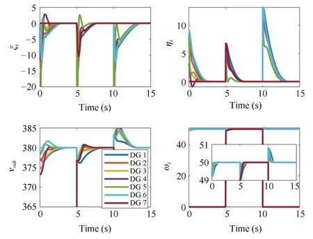
Fig.11. Case Study (iv)-Results with a DG 7 is added at t = 5 s and then is removed at t=10 s.
APPENDIX A
In this section, we present how to derive the expressions of fi(xi), ki(xi), Di, gi(xi), and hi(xi) in (5). Note that the materials of this section are summarized based on the work in [12], [31]-[33].
The angle of the ith DG reference frame with respect to the common reference frame is denoted as δi. The dynamics of δican be written as

where ωiis the rotation frequency of the ith DG reference frame, and ωcomis the rotation frequency of the common reference frame.
The power controller dynamics can be written as

where vodi, voqi, iodi, ioqiare the direct and quadrature components of output voltage voiand output current ioi, ωciis the cutoff frequency of a low-pass filter, Piand Qidenote the output active and reactive powers, respectively.
Since the primary voltage control strategy aligns the output voltage magnitude of each DG on the d-axis of the corresponding reference frame [8], one obtains

The voltage and current controller dynamics can be written as
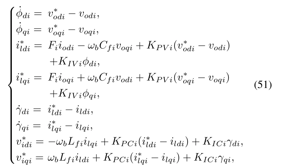
where φdi, φqi, γdi, γqiare the auxiliary state variables, and ωbis the nominal angular frequency.
The output LC filter and output connector dynamics can be written as

From (48)-(52), the large-signal dynamical model can be written in a compact form as

where the state vector is

and Di= [ωcomvbdivbqi]T. The detailed expressions for fi(xi), ki(xi), gi(xi), hi(xi) can be derived from (48)-(52).
杂志排行
IEEE/CAA Journal of Automatica Sinica的其它文章
- Ground-0 Axioms vs. First Principles and Second Law: From the Geometry of Light and Logic of Photon to Mind-Light-Matter Unity-AI&QI
- Nonsingular Terminal Sliding Mode Control With Ultra-Local Model and Single Input Interval Type-2 Fuzzy Logic Control for Pitch Control of Wind Turbines
- Deep Learning for EMG-based Human-Machine Interaction: A Review
- Deep Learning in Sheet Metal Bending With a Novel Theory-Guided Deep Neural Network
- Autonomous Control Strategy of a Swarm System Under Attack Based on Projected View and Light Transmittance
- Computing Paradigms in Emerging Vehicular Environments: A Review
