Evaluation of load transfer mechanism under axial loads in a novel coupler of dual height rock bolts
2021-04-08RnjnKumrPrhtKumrMndlAshishNrynArkJyotiDs
Rnjn Kumr,Prht Kumr Mndl,*,Ashish Nryn,Ark Jyoti Ds
a CSIR-Central Institute of Mining and Fuel Research,Dhanbad,Jharkhand 826015,India
b Chaibasa Engineering College,Kelende,Jharkhand 833201,India
Keywords:Roof rock reinforcement Dual height rock bolts Rock bolt coupler Expansion shell Underground mining Laminated roof strata
ABSTRACT The effective reinforcement of two or more overlying layers of mine openings in a single installation is usually done by coupling of two standard rock bolts mainly during the extraction of medium-thick coal seams.However,field observations show that the couplers of multiple bolts often degrade or break mostly at their connections.These types of failures can be avoided by strengthening the couplers of such multi-bolts assemblies.To achieve this,a novel threaded coupler system with an expansion shell was suggested in this paper.The newly designed coupler consists of a threaded tapered-plug-cumconnector with an expansion shell for connecting and tightening two standard rock bolts.An analytical model for evaluating the load distribution along the coupler subject to axial load was derived.Numerical analysis was performed to analyse the load transfer,deformation,and strains across the coupler including the factor of safety for the bolt-coupler-resin and bolt-coupler-expansion shell.The results validated the analytical model of the proposed coupler design,which provides better anchorage near the interface of the host rock mass.Thus,the developed coupler design would reduce the failures of the proposed coupler and stabilize laminated roof strata above the medium-thick coal seams in underground mines.
1.Introduction
Roof rock strengthening using rock bolts is a proven method of stabilizing openings in mines,tunnels,and other excavations.When rock bolt is used properly in any excavation,it offers the best and the most economical means of binding the rocks in place.If the seam is medium-thick or highly thick,the standard bolt length may not be sufficient to bind beyond their lengths.For example,the roof rock during the excavation of coal seams of medium thickness under massive igneous rocks in Western Coalfields of India is reinforced mainly by a dual-stage rock bolting system[1]as shown in Fig.1 (H is the height of roadway and T is the thickness of coal seam in Fig.1).In the first stage,rock bolts of standard length are installed in the coal roof while developing galleries and in the second stage,rock bolts are installed in the stone roof while retreating,as shown in Fig.1a.This leads to the installation of the secondary supports.This is highly unsafe,particularly in the second stage because drilling in the roof under dynamic stress may lead to the collapse of the roof in the workings.Sometimes,the longer cable bolts are used to bind the two layers of coal and the overlying rock mass during development.However,overhanging cable bolts left during retreat may be dangerous to the mining activities,as shown in Fig.1b.
These risky situations can be avoided by replacing the twostage bolting with single-stage bolting.In single-stage bolting,two or more coupled rock bolts,dual height rock bolts (DHRB),are installed in the exposed roof of the thick coal seam to bind up it with the overlying stone layers.These are the combination of rock bolts,which offer a good option to rock mechanics engineers to install multiple bolts in a single installation [2-4].In this type of bolts,the resin-rebar of standard length is attached with mechanical bolts and placed in the borehole of twice the length.In traditional DHRB,the mechanical bolt is screwed into the connector piece welded to rebar which allows the bolt to be torqued.The connector piece is placed above the pressure arch in the unfractured rock to provide a reliable anchor.These types of roof bolts are also suitable for weak strata at the anchorage horizon and weak surface at the hole’s mouth.However,the bilayers or multilayers strata with the interface of different rock layers generate shear stresses,which often may lead to loosening or failures at couplers of two rock bolts.Additionally,the combination bolts are found broken at thread near the coupler in field conditions [2].
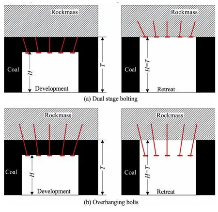
Fig.1.Dual-stage supports during development and retreat operations in thick coal seams.
Several numerical investigations of threaded connections to study the coupling behaviour of nut and bolt connections have been reported in the literature [5-7].Further,a divergence between experimental outcomes and the prevailing concept exists for the load spreading in the threaded coupling of nut and bolt assembly [8].Recently,the relevant finite element analysis of the threaded fasteners and connectors has been analysed in 3D finite element analysis[9-13].But,all these investigations were focused on the study of threaded nut and bolt connections.The comprehensive literature survey found that no prior research reports investigated the behaviour of couplers of DHRB or a combination of rock bolts in the rock mass.Thus,the design of the coupler of these combination bolts is similar to the conventional nut-bolt type designs and prone to failures under the complex nature of rock mass loadings during the excavation in underground mines.
The improvement in the design of the coupling mechanism of DHRB is highly required to strengthen the threaded portion of the coupler to avoid its failures after installations in the roof rock strata.Taking a cue from the shortcomings in the existing design of the threaded coupler and loading patterns of the rock mass,this paper suggested a novel design of the threaded coupler with an expansion shell for improving the strength and anchorage of the coupler.The gripping of the expansion shell over the coupler may improve its strength due to the anchorage force that resists the radial deformation of the threads near the connection.The newly designed coupler allows the installation of multiple rock bolts in a single-stage,which will economize the support system and enhance the safety in the extraction of medium-thick coal seams.
To evaluate the effectiveness of the developed design of the DHRB coupler,this research work formulated an analytical model of load distribution along the DHRB coupler installed in the rock mass and subject to varying axial loads.To verify the results of the developed analytical model,numerical analysis using axis symmetry 2D finite element analysis is performed in two cases of the DHRB coupler assemblies namely bolt-coupler-resin and boltcoupler-expansion shell.The load transfer,deformation,and strains across these couplers and their factors of safety are estimated and compared for the two cases.
2.Novel design of coupler of dual height rock bolts
A new type of mine roof bolt assembly [14]is developed in which the upper and lower bolt rods are connected by a novel coupling mechanism with sufficient stiffness,as shown in Fig.2.The novel threaded coupler is a tapered plug-cum-connector forged with the upper bolt as shown in the inset of Fig.2.The two expansion shells are provided just up and below of the threaded coupling and expanded with forged tapered plug-in at the lower end of the upper bolt and tapered plug-in at the upper end of the lower bolt with equal rotation.These expansion shells provide gripping at the coupler.The two support nuts,one fixed to the top expansion shell and the other at the bottom expansion shell are provided to resist the expansion of the shell beyond the threaded portion of the bolt rod.The upper bolt is fully grouted with resin capsule and the lower one is mechanically tensioned at the bearing plate.
This design can eliminate the requirement of secondary support leading to a more efficient and economical roof support system.This unit has internal threading,which connects the lower bolt assembly as shown in Fig.2b.Over the tapered surface of the coupler,a customized upper expansion shell of two serrated flanks is provided which expands over the forged tapered plug-cumconnector to provide cohesive bonding and frictional interlock with the borehole surface just above the connection of two bolts.The installation in a borehole is done by screwing the lower bolt for tightening the lower and the upper expansion shells simultaneously.
2.1.An analytical model of load transfer in coupled rock bolts subject to axial load
During the installation of the DHRB threaded coupler,the expansion shell slides down over the coupler and is pressed towards the borehole wall.Thereby the borehole wall resists the expansion of the shell and provides frictional resistance and cohesion at the interface of the tapered coupler surface and borehole surface.Based on the shear coupling spring model,the shear resistance at the interface can be obtained by the coupling spring shear stiffness during the movement between the rock bolt nodes and the grid[15].Thus,the maximum shear resistance along the interface of the DHRB coupler and the rock mass depends on the cohesive strength and the frictional resistance of the interface[16].The maximum shear force per length of DHRB coupler along the interface is the sum of cohesive strength of the interface and the frictional resistance along the interface and expressed by Eq.(1)[16,17].

2.1.1.Estimation of cohesive resistance along the expansion-shell/rock interface
As shown in Fig.3,the contact length of the i-th ES flank (Si)with the borehole surface varies and the total shear stress over the contact area around the DHRB coupler should be balanced by the applied axial stress for stable anchorage.
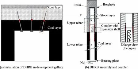
Fig.2.Dual height rock bolts (DHRB) with a threaded coupler in a typical coal mine opening.

Fig.3.Schematic of distribution of shear stress along the elementary length dy at the interface.
The relationship between shear resistance,τ(y),of element dy of i-th contact length,Si,and axial stress,σ(y),at y distance from the collar of the coupler can be expressed by Eq.(2) or Eq.(3).

where p and A are the perimeter and area of cross-section of DHRB coupler at the interface,respectively.Thus,the cohesive resistance distribution along the DHRB coupler can be derived from Eq.(3).
Using the bond-slip mode [17-19],the axial stress,σ(y),of the DHRB coupler at y distance from the free end of the coupler can be given by

where E is the modulus of elasticity of DHRB coupler;and ε(y) the strain at y distance.
From Eqs.(3) and (4),the local shear stress distribution along DHRB coupler becomes

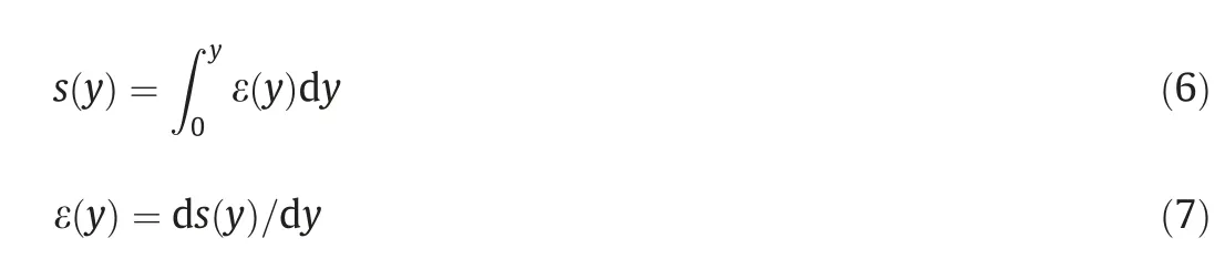
The relative axial displacement or slip,s(y),along the interface at any point y,can be defined by Eq.(6) or Eq.(7).
Thus,the shear resistance distribution along the bolt can be expresses by Eq.(8).

Ma et al.[19]considered,s(y)=aln[1+exp((y-y0)/b)]for slip distribution and derived the shear resistance distribution at distance s along the bolt-resin/rock interface subject to axial load,P(s),can be expressed by Eq.(9).

where A’is the contact area;a the peak elastic slip or the slip at the turning point of the load-slip curve;b the initial tangential stiffness of the load-slip curve;and s0a coefficient determined from tests[20].
However,the above equation is not directly applicable because the suggested design of the DHRB coupler is in contact with the borehole surface through the flanks of ES.In other words,the contact area,A’,depends on the contact length (Si) of each flank varying with the tapered angle and confining stress from the host rocks,as shown in Fig.3.Therefore,the area at i-th flank may be given as

where A’iis the the area of contact of i-th flank;A0=π(D2/2) the area at i-th flank for contact length at Si=0;D the diameter of borehole;and m the axial length of the flank of expansion shell.Additionally,the (si-si-1) can be simply taken as contact length,Si,because the cohesive resistance varies from one flank to another flank because of the tapered surface.Therefore,the cohesive resistance at i-th flank of the expansion shell,Fc(i),can be expressed by Eq.(11).

2.1.2.Estimation of frictional resistance at expansion-shell/rock interface
Frictional resistance can be given by Eq.(12).

where μ is the co-efficient of frictional resistance;φ the internal angle of friction between flank and rock mass interface;and σcthe mean effective confining stress.
The load distribution in the threaded connection may depend on the length of contact(Si)of the ith flank of expansion shell with borehole rock wall and,as shown in Fig.4.The determination of the length of contact (Si) around the borehole surface depends on the number and dimensions of the flank of expansion shell (i,n,m),the angle of the tapered surface of the coupler (θ),and length of the expansion shell (Les),and the diameter of the borehole (D).
Thus,the Sifor i-th flank can be deduced by the law of proportionality.

where m,n,and x are the height,base,and gap between tapered surface and rock,respectively;and y the distance of flank base from the free face.The frictional resistance of the threaded coupler can be given as follows.

Using Eqs.(16) and (17),the frictional resistance at i-th flank can be estimated from Eq.(18).

Eq.(18)can be added to the cohesive resistance at the interface to determine the load distribution across the DHRB coupler subject to the axial load.
2.2.Load distribution across the DHRB coupler subject to the axial load
Using Eqs.(1),(11),and (18),the analytical expression for the load distribution across the DHRB coupler can be as follows.
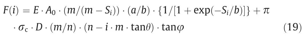
where F(i)is the total shear resistance at i-th flank of the expansion shell.
However,these analytical expressions may not be utilized for irregular geometry or modified geometry of the threads with varying applied load and complex set of boundary conditions.Further,combined load conditions of shear,axial,and bending exist in the rock bolt system[21].Therefore the numerical analysis is essential to evaluate the strengths of the threaded coupling system introduced here.

Fig.4.Schematic of contact length (S) of expansion shell flank with the borehole wall.
3.Numerical modelling for load transfer evaluation
Numerical modelling of the DHRB coupler provides an essential tool to cross verify the analytical results for the DHRB coupler.Therefore,this section attempts to analyze the load transfer,strains and deformation across the DHRB coupler and its factor of safety.The factor of safety ensures that the design of the coupler system is stable and functional.
3.1.Problem formulation
To cross-verify the analytical results and comparative study of DHRB coupler,the numerical modelling exercise considers the two settings of DHRB coupler,one with ES and another with resin,for finite element analysis as shown by the dotted zone in the schematic diagram of Fig.5.The first case,as shown in Fig.5a,includes bolt,coupler,resin(B-C-R)and sandstone as the host rock.The second case of the bolt,coupler,expansion shell (B-C-ES) and sandstone is shown in Fig.5b.
The numerical model exercise aims to create a computation model of the two assemblies with all the boundary conditions and applied loads.The behaviour of the coupler system concerning varying axial loads is analysed in terms of load transfer from inner threads to outer threads,deformation and overall factor of safety.The numerical analysis can provide the proper number of threads required to couple two bolts strongly enough for reinforcing two layers of the laminated strata in underground coal mines.
3.2.Geometry,grid,and boundary conditions
The model geometry of two assemblies used in the analysis is illustrated in Fig.5a and b,respectively.The study domain of these assemblies contains a bolt of fifteen threads with a diameter of 22 mm and the length of 70 mm,a coupler tapered in shape with a diameter at one end of 24 mm and the other end of 27 mm.The lengths (i.e.60 mm) of the coupler and sandstone,host rock,are taken equally.The 2 mm gap between coupler and host rock is filled with two options i.e.resin and expansion shell.
The computational grids,as given in Fig.6,are constructed with variable mesh size using ANSYS workbench software for evaluating the load transfer for two combinations of assemblies,B-C-R and BC-ES[22].Grids vary from approximately 6836 to 11420 are generated for a different combination of assemblies.The finer grids are generated in the regions to acquire the results and the coarse where the effects are less 200000.

Fig.5.Model geometry of the B-C-R and B-C-ES (unit:mm).
The grid sensitivity analysis has been done by varying cell number:6836,8746,and 11420.The analysis showed that the current results attained with 6836 cells are practically invariant to additional grid refinement.The variation of equivalent stress with position along the free end of the nut for various grids is shown in Fig.7 at a bolt,coupler and resin assembly.
As shown in Fig.5a and b,the boundaries of the upper part and sandstone sides are fixed in the model geometry of both the assemblies.The axial load is applied to the rock bolt downward and the cohesive and frictional contact is considered between expansion shell and rock mass.Additionally,the frictional contact has been considered for the rest of the interfaces,as shown in Table 1.In this numerical model,the stainless steel which is ductile material has been used for the bolt,coupler,and expansion shell.The material properties of rock bolt,coupler,expansion shell,sandstone,and coal are summarized in Table 2.
The Mohr-Coulomb failure criterion has been considered for both the assemblies.The varying axial loads have been applied to the free end of bolt outward of the model geometry of B-C-R and B-C-ES to determine the geometry and loading condition for better performance of bolt and coupler assemblies.
4.Results
The results of the numerical simulation of B-C-R and B-C-ES models using ANSYS workbench software for evaluating the load transfer,strains and deformation,and factor of safety for two combinations of assemblies are given below.
4.1.Load transfer in threads
The summation of the axial component of the root as well as the tip load for each thread of B-C-R and B-C-ES are given in Table 3.It is observed that the summation of the root,as well as tip load,is the same as the 40 kN of axially applied load at the bottom end of the bolt.The trend analysis has been done with numerical results of total load distribution in B-C-ES assembly.Figs.8 and 9 show the regression co-efficient with the best-fit curve of the second-order polynomial for B-C-R and B-C-ES assemblies,respectively.In Figs.8 and 9,the trend shows that the axial load applied to the bolt is distributed higher to the threads close to the free end and becomes zero at the threads away from the free end.From Figs.8 and 9,it may be observed that the lesser number of threads required to dissipate the axial load in B-C-ES than those in B-C-ES.In other words,the shorter length of the coupler in the case of B-CES may be sufficient than that of B-C-R assemblies.
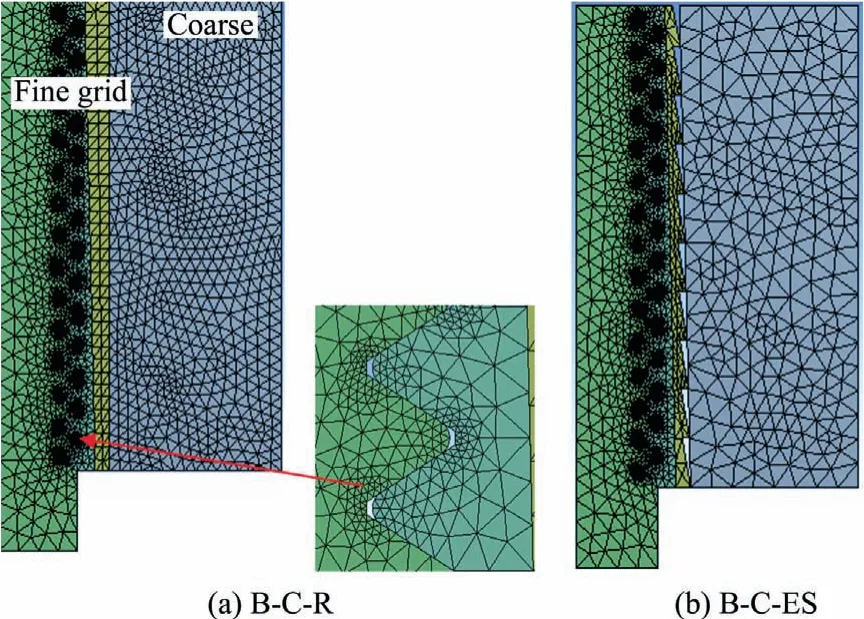
Fig.6.Computational grid of B-C-R with inset near the interface and B-C-ES.

Fig.7.Variation of equivalent stress with the position for various grids showing grid sensitivity.

Table 1 Frictional properties over the contact surfaces.
Moreover,Fig.10 shows that gripping at the lower end in B-CES assembly at threads closer to the free end of the coupler is stronger than that in the case of B-C-R.This finding provides a significant insight that load transfer from bolt to coupler is better in B-C-ES assembly at threads close to the free ends.This is also corroborated by the shear force estimated from the analytical equations (Eq.(19).
As shown in Fig.11,the comparative estimates of load distribution across the threads are made using numerical,statistical,and analytical studies.The trend of load distribution along the threads of rock bolt and couplers estimated by the analytical equation,Eq.(19),is almost similar to the numerical analysis (see Table 4).Therefore,the analytical expression for shear resistance in B-C-ES is quite valid in estimating the load distribution along the newly designed threaded coupler.
4.2.Strains and deformation
The study of different types of strains and deformation across the threaded coupler in two assemblies have been made by applying 40 kN load axially to the free end of the lower bolt.
Fig.12a illustrates the deformation along with the thread interface of the lower bolt and the coupler and it can be inferred that the deformation for the B-C-ES is lower than that of B-C-R.Moreover,the total strain produced in B-C-ES assembly is also lower than that of B-C-R as shown by Fig.12b.
4.3.Factor of safety of the coupling mechanisms
The comparative study of the factor of safety for a different combination of assemblies such as B-C-R and B-C-ES has been conducted and the estimated factor of safety values summarized in Table 5.In the numerical analysis,the stainless steel is used for coupler and bolt which is a ductile material.If Sfis the material yield strength and σmaxis the maximum stress from the analysis,the factor of safety for the ductile material can be estimated by the following expression.

where FoS is the factor of safety.

Table 2 Material properties.
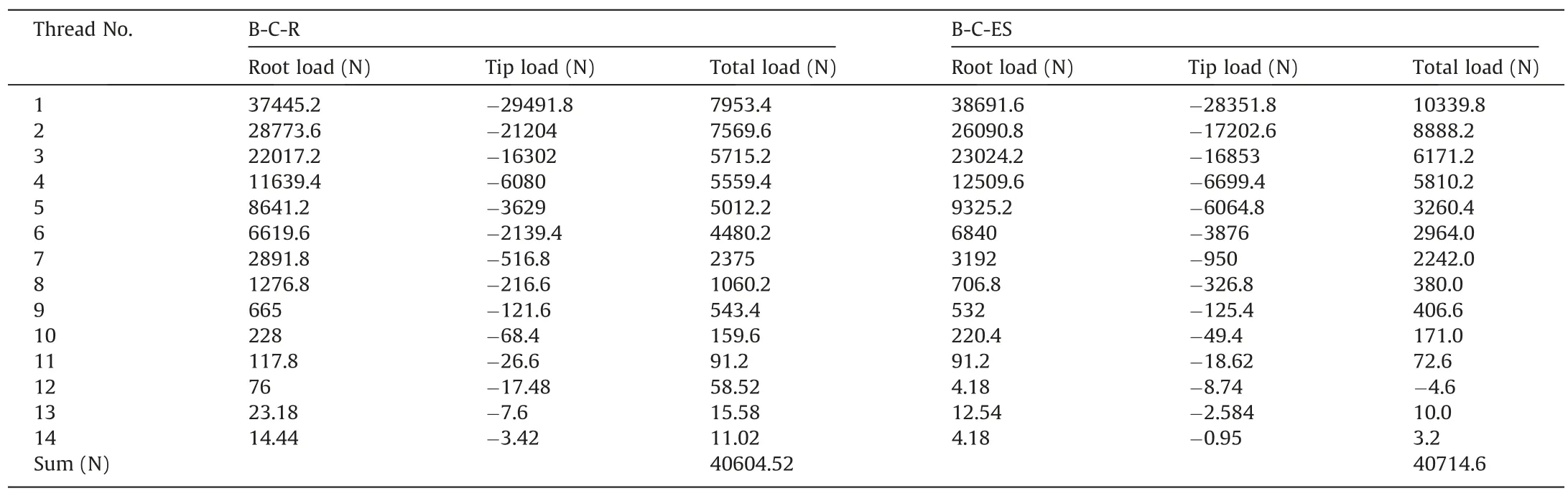
Table 3 Load transfer in coupler thread.

Fig.8.Trend curve of load transfer from bolt to coupler with resin (B-C-R).

Fig.9.Trend curve of load transfer from bolt to coupler with an expansion shell(BC-ES).
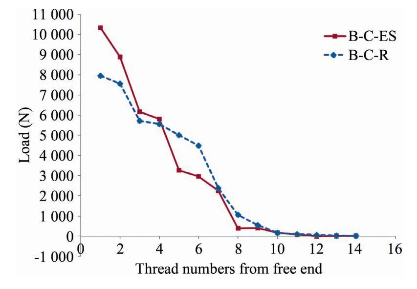
Fig.10.Thread-wise total load transfer from bolt to couplers.
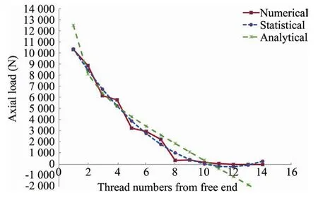
Fig.11.Thread-wise total load transfer from bolt to coupler with an expansion shell.

Table 4 Comparative load transfer in the threaded coupler of B-C-ES.
The contours of factor of safety across the domain are illustrated in Fig.13.It is noticed that the factor of safety is increased when introducing the expansion shell and resin.Hence,as per the present study,the nut,bolt and expansion shell are the better combination than the other assembly.
5.Discussions
To realize the reinforcement of two layers of different roof rocks in a single installation,a new design of the coupler system is introduced to attach and install two assemblies of rock bolts(termed as DHRB) in a single-stage.Additionally,the designed coupling system allows lower deformation,better load transfer at threads close to the free end of the coupler.The finite element analysis has been performed on the two cases of coupler system to study the gripping at the coupler,load transfer from lower bolts to upper bolts through the threaded coupler,deformation and overall factor of safety.The values of these parameters are essential for the successful coupling of two rock bolt assemblies with different reinforcement mechanisms in providing adequate supports in laminated roof strata in underground coal mines.
As summarized in Tables 3 and 4 and illustrated in Figs.8-11,the results of finite element analysis establish that the material between the borehole wall and the threaded coupler influences the load transfer from inner thread to outer thread.The first thread of the bolt assembly of bolt-coupler-resign (B-C-R) is subjected to lower load transfer than that of the bolt assembly of bolt-couplerexpansion shell (B-C-ES).The load transfer in both the assemblies converges to 1 N after thread number 15 from the free end of the threaded coupler.This indicates that 15 threads are sufficient enough to transfer complete load from inner to the outer thread of the coupler.The significant outcome of this result is that the bolt assembly of B-C-ES provides better gripping at the initial threads close to the free end of couplers.
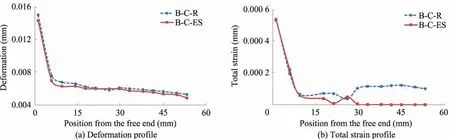
Fig.12.Deformation and total strain at threads with 40 kN axial loads.
As shown in Fig.12,the deformations and the strain along the coupler’s thread from the free end have been studied on two assemblies,B-C-R and B-C-ES applying a constant axial load of 40kN on lower bolt.The trends of axial stresses and deformations at threads were observed to be the lowest in B-C-ES-R combination.However,the values total strains dropped sharply along the distance from free face and were the lowest in B-C-ES assembly.Therefore,it can be concluded that the B-C-ES combination of coupling is very effective in dual height rock bolt system.Finally,the results as summarized in Table 5 and illustrated in Fig.13 indicate that the assembly B-C-ES has better values of factor of safety for the same applied load at lower bolt assembly.One of the important conclusions can be deduced that the assemblies almost started to fail structurally at an applied load exceeding 150 kN.In sum,the findings in this work may lead to an innovative design and practical installation of dual height rock bolts to stabilize weak layered roof strata optimally in underground coal mines.

Table 5 Factor of safety for different assemblies with varying axial loads.
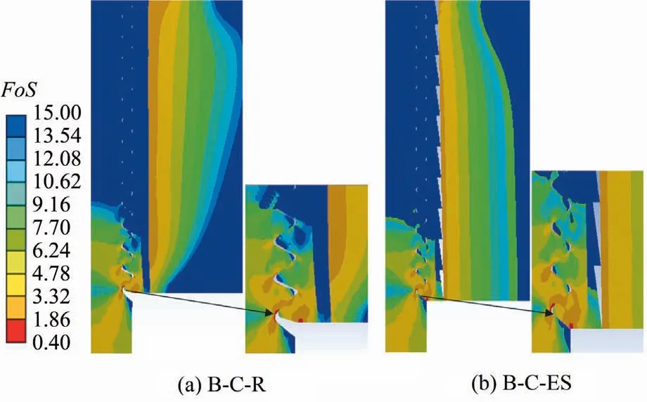
Fig.13.Contour of factor of safety for B-C-R and B-C-ES assemblies.
6.Conclusions
This paper introduced a novel design of a coupling system for dual height rock bolts that can be used to reinforce weak laminated strata beyond the height of the standard rock bolt in a single installation.The novel design includes a threaded tapered-connectingplug forged with the upper bolt and covered with an expansion shell.To evaluate the load distribution across the coupler,a new analytical model is developed taking into account the interaction of expansion shell and host rock mass of the borehole.To verify the estimation of the analytical model and analyse the load transfer,deformation,and strains across the coupler and its factor of safety,numerical analysis using finite element modelling are performed for the two cases of coupling mechanisms namely,boltcoupler-resin and bolt-coupler-expansion shell under given host rock.The load transfers from inner thread to outer thread,deformation across the thread,the factor of safety of the threaded connections has been investigated.The results indicate that the factor of safety for the threaded coupling with expansion shell is higher than that for the threaded coupling with resin under the given host rock.The results obtained in this study establish that the newly designed coupler with an expansion shell improves its strength,which may reduce the chance of breakage at the threaded connection.This novel coupler along with the DHRB will be beneficial for the extraction of coal,especially,from the medium-thick coal seams.
Acknowledgement
The authors are thankful to the Director,CSIR-Central Institute of Mining and Fuel Research,Dhanbad for permitting this research work for publication.The views expressed in this paper are that of the authors and not necessarily of the organization they belong to.
杂志排行

矿业科学技术学报的其它文章
- Evaluation of the use of sublevel open stoping in the mining of moderately dipping medium-thick orebodies
- Stability control of gob-side entry retained under the gob with close distance coal seams
- A novel coating technology for fast sealing of air leakage in underground coal mines
- A robust approach to identify roof bolts in 3D point cloud data captured from a mobile laser scanner
- Physical model test and numerical simulation on the failure mechanism of the roadway in layered soft rocks
- Deformation response of roof in solid backfilling coal mining based on viscoelastic properties of waste gangue