Stability control of gob-side entry retained under the gob with close distance coal seams
2021-04-08ZizhengZhngMinDengJinioBiShuiYnXinyngYu
Zizheng Zhng,Min Deng,Jinio Bi,Shui Yn,Xinyng Yu
a Work Safety Key Lab on Prevention and Control of Gas and Roof Disasters for Southern Coal Mines,Hunan Provincial Key Laboratory of Safe Mining Techniques of Coal Mines,Hunan University of Science and Technology,Xiangtan 411201,China
b State Key Laboratory of Coal Resources and Safe Mining,China University of Mining and Technology,Xuzhou 221116,China
c Jiangsu Engineering Laboratory of Mine Earthquake Monitoring and Prevention,School of Mines,China University of Mining and Technology,Xuzhou 221116,China
Keywords:Gob-side entry retaining Close distance coal seams Damage factor Interlayer rock strata Side-roadway backfill body
ABSTRACT In multi-seam mining,the interlayer rock strata between the upper coal seam (UCS) and the lower coal seam(LCS)appear damage and strength weakening after mining the UCS.Ground stability control of the gob-side entry retaining (GER) under the gob with close distance coal seams (CDCS) is faced with difficulties due to little attention to GER under this condition.This paper focuses on surrounding rock stability control and technical parameters design for GER under the gob with CDCS.The floor rock strata damage characteristics after mining the UCS is first evaluated and the damage factor of the interlayer rock strata below the UCS is also determined.Then,a structural mechanics model of GER surrounding rock is set up to obtain the main design parameters of the side-roadway backfill body (SBB) including the maximum and minimum SBB width calculation formula.The optimal SBB width and the water-to-cement ratio of high water quick-setting material (HWQM) to construct the SBB are determined as 1.2 m and 1.5:1.0,respectively.Finally,engineering trial tests of GER are successfully carried out at#5210 track transportation roadway of Xingwu Colliery.Research results can guide GER design under similar mining and geological conditions.
1.Introduction
Gob-side entry retaining(GER)technology refers to retention of the initial entry through effective in-roadway reinforcement and side-roadway support during the advancing of the working face(Fig.1) [1-3].Since the original roadway is maintained behind the working face,GER technology can realize the roadway protection without coal pillar in the mining area,which not only greatly improves the recovery rate of coal resources but also avoids some problems caused by retaining coal pillar in the zoned section.Moreover,the retained roadway,as an air-return roadway,can realize the working face ventilation with Y-type,which fundamentally greatly reduces the gas concentration.Therefore,it is a key technology with significant technical and economic benefits.It is also significant for the sustainable development of coal resources[4-6].
GER technology has been widely used in China in the last century.In the early stage,the mined coal seams were generally thin in British,and gangue bands were often used to support the sideroadway for GER,and mechanized masonry devices were developed for gangue bands.High water quick-setting material(HWQM) began to be used to construct the SBB in 1979 [7].For Germany,the pigsty and gangue bands were used to support the side-roadway for GER previously.In the late 1960s,the gypsum,fly ash,coal gangue cement,and Portland cement have been employed to construct the SBB successfully.The proportion of low-water materials used as side-roadway backfill materials is 1/2-2/3,and it has been successfully conducted in the roadway with a cover depth of 800-1000 m [8].At present,collieries tend to be shut down in Germany.Russian experts also made a lot of research work,including the strata behavior characteristics of GER by using similar simulation experiments and side-roadway backfill material properties,strength,and yielding of the support for GER.In the 1950s,GER technology in China began to carry out in the coal seam below 1.5 m thick,while the gangue bands were used as side-roadway support and the wooden shed was mainly used for roadway support.In the 1970s,the side-roadway support began to adopt concrete blocks and dense metal pillars and was successfully applied to the medium-thick coal seam(1.3-3.5 m).In the 1980s,China successfully introduced backfill materials and backfill equipment from Britain and Germany,and carried out industrial tests in Yangquan,Kailuan,Pingdingshan,and other mining areas,achieving good results.It is gradually realized that the SBB should have the characteristics of limiting deformation and the properties of adapting deformation during the process of GER.Since the 21st century,with the popularization and application of rock bolt support technology and the continuous improvement of side-roadway backfill technology,many fully mechanized mining working faces and fully mechanized caving faces have carried out the experimental research of GER technology and achieved good results [9-13].The key to the success of GER technology is the reasonable choice of side-roadway support and in-roadway support.
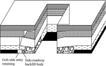
Fig.1.Sketch of a working face with GER.
Multi-seam mining including ascending mining and descending mining has widely existed in major coal mining countries [14,15].After the upper coal seam (UCS) is mined out,the interlayer rock strata are seriously damaged,and even the loose structure is formed.The roof leakage and collapse accidents of the lower coal seam(LCS)are easy to occur when mining the UCS.In recent years,Chinese scholars have made plentiful studies on the mine pressure and strata control under the condition of multi-seam mining,mainly focusing on the roof structure and stability control of the LCS [16],the technology of joint mining of close distance coal seams(CDCS),the mine pressure characteristics[17],and the fracture and control of multi-layer roof under multi-gob [18,19].Hou et al.investigated the damage laws of the floor caused by mining the upper coal seam by adopting the continuum damage model[20].Interlayer rock strata are mostly assumed to be nondestructive or completely damaged in the last studies,but few studies have been conducted on the damage law of interlayer rock strata.Therefore,GER of the LCS is with a fractured and soft roof after mining of the UCS.It is essential to take into consideration the damage characteristics of interlayer rock when designing the GER of LCS.Zhu et al.proposed pier column GER technology with the soft roof in a thin coal seam of Dongda Colliery[21].According to the conditions of the soft roof and soft floor in a thin coal seam of Zhaoguan Colliery,it is recommended to build a waste stone wall in the gob first,then timely build cemented filling body and long steel beams and monomer pillar support in the roadway at last[22].Tian et al.proposed the GER technology with a SBB constructed by HWQM under the condition of the soft roof and soft floor in a thin soft coal seam of Heilong Colliery [6].It is observed that most of the reported GERs with a soft roof are carried out in thin coal seams,of which the thicknesses are less than 1.3 m.
Hence,this paper firstly evaluates the damage laws of the interlayer floor caused by mining the UCS by establishing the continuum damage model.Secondly,the SBB width and strength parameters are basically assumed by the theoretical model.Moreover,numerical simulations are employed to determine the reasonable SBB width and strength parameters.Finally,engineering trial tests are carried out at the #5210 track transportation roadway of Xingwu Colliery.
2.Engineering background
The engineering site in this paper was the #5210 track transportation roadway of Xingwu Colliery,located in Lvliang City of China.The #5210 track transportation roadway is located under the #42208 working face,which has been mined out.The average space between the#4 and#5 coal seam is 6 m.The average thickness of the#4 and#5 coal seam is 3.5 and 1.6 m,respectively.The average dip angle of the #4 and #5 coal seam is 5° and 4°,respectively.The average cover depth of the #5210 working face is 276 m.Figs.2 and 3 show the plan layout and the lithology of the #5210 working face,respectively.
To solve the difficult ventilation problem,reduce the gas concentration,relieve the mining replacement tension,and improve the recovery rate,GER technology could be carried out in #5210 track transportation roadway.
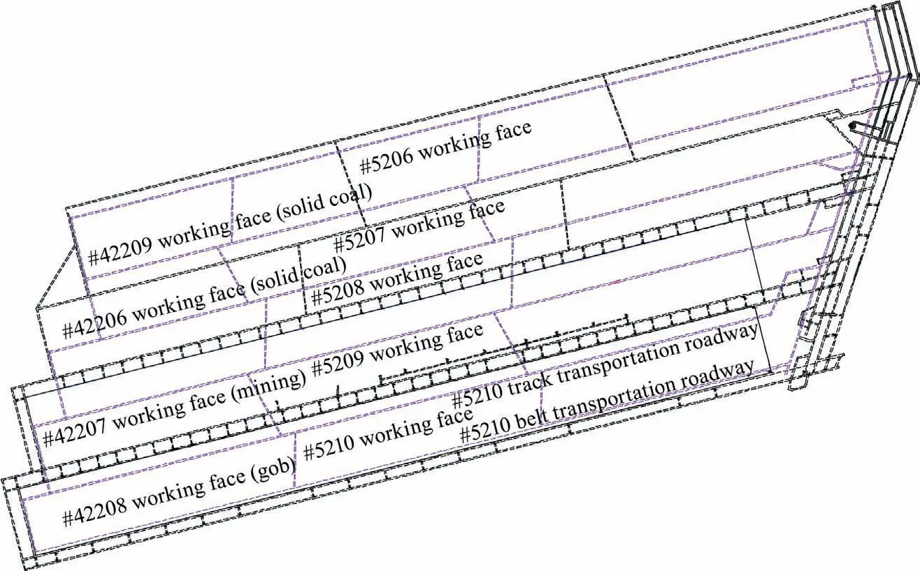
Fig.2.Layout of the #5210 working face (Magenta color for #5 coal seam,black color for #4 coal seam).
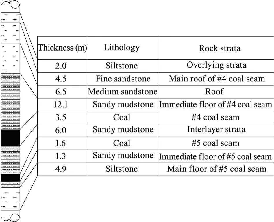
Fig.3.Lithology of the #5210 working face.
The #5210 track transportation roadway is designed to be 2127.2-m long,2.6-m high,and 4.5-m wide.The #5210 cut-off is 150-m long,and is 2048.4 m away from the stop-production line.The initial design of bolt support parameters of#5210 track transportation roadway is as follows.The support section diagram is shown in Fig.4.
Φ20 mm × 2.5 m left-hand thread steel bolt was adopted to support the roof with resin cartridges (one CK2340,one Z2360).The rock bolt anchorage force is 120 kN,and pre-tightening torque is not less than 200 Nm.Also,the diamond steel mesh was set up on the roof.The steel ladder beams (2.4 m long) were laid to connect all of the rock bolts.Meanwhile,Φ18.9 mm × 5.2 m anchor cables were also used to support the roof.Φ20 mm × 2.0 m lefthand thread steel bolt support was adopted to support ribs with resin cartridges (one CK2340,one Z2360).Also,the diamond steel mesh was set up on the ribs.The steel ladder beams (4.3 m long)were laid to connect all of the rock bolts.The row spacing of the rock bolts and anchor cables were 800 mm and 1600 mm,respectively.
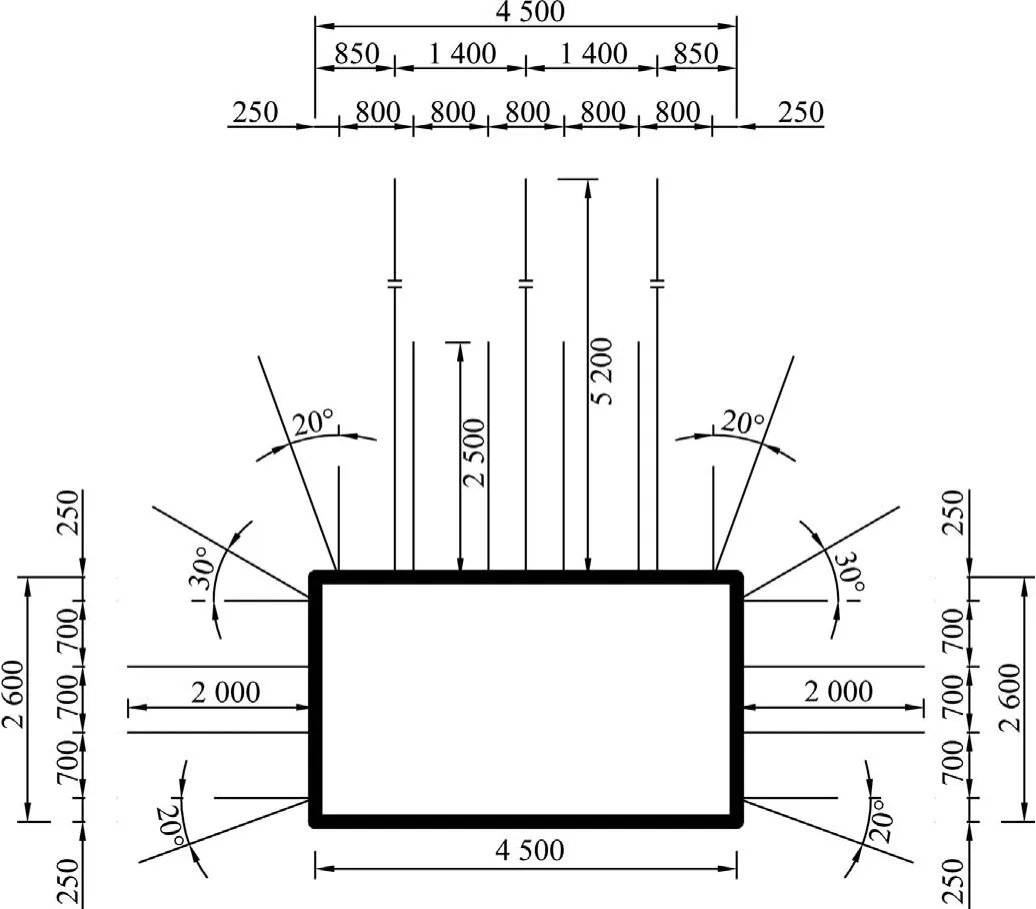
Fig.4.Support section diagram of#5210 track transportation roadway(unit:mm).
3.Damage laws of the interlayer rock strata due to mining the UCS
3.1.Damage analysis of interlayer rock strata due to mining the UCS
The space between the UCS and LCS has a significant impact upon the mining of the LCS.If the space between the UCS and LCS is small,it is necessary to study the damage depth of the lower rock strata due to mining the UCS,to determine whether the mining of the UCS has an impact on the lower rock strata.
The ultimate load of the floor rock strata can be obtained by the plastic slip theory.Thus,the maximum failure depth of the floor rock strata,hmax,is shown in Eq.(1) [23].

where φiis the friction angle of the interlayer rock strata in degree;and lpthe limit equilibrium zone width in m,determined by Eq.(2)[24].

where c0is the interface cohesion between the#4 coal seam and its roof in MPa;φ0the friction angle between the#4 coal seam and its roof in degree;p0the solid coal rib support strength in MPa;A the horizontal pressure coefficient;h4the height of the#4 coal seam in m;k the stress concentration factor of the #42208 working face;H the cover depth of the #4 coal seam in m;and γ the average bulk density of overlying strata in kN/m3.
Eq.(3)shows the maximum failure depth of the floor rock strata(hmax) when substituting Eq.(2) into Eq.(1).

According to the in-situ tests,the mining stress concentration factor of the #42208 working face can be assumed as 2.5.According to the laboratory tests,the interface cohesion and the friction angle can be assumed as 1.0 MPa and 20°,respectively.The friction angle of the interlayer rock strata is 30°.Meanwhile,γ and p0can be assumed 2500 kN/m3and 0.15 MPa,respectively.Substituting these parameters into Eqs.(2) and (3),then we have lp=5.4 m and hmax=8.54 m.Therefore,the interlayer rock strata,the#5 coal seam,and 0.94-m thick immediate floor of the#5 coal seam show damage and strength attenuation.Moreover,the mining-induced damage effect should be considered when the GER ground control of #5 coal seam is designed.
3.2.Damage factor of interlayer rock strata due to mining the UCS
Based on the continuous damage factor proposed by Kachanov,Lemaitre’s strain equivalence theory and Weibull statistical theory were used to establish a statistical damage mechanics analysis method.According to the calculation method developed by Cao et al.[25]and Hou et al.[20],considering the damage threshold of rock material and assuming that the strength of rock element conforms to Mohr-Coulomb criterion,the damage factor of the interlayer rock strata can be determined by Eq.(4).

where D is the damage factor of the interlayer rock strata;c the cohesion at yield;φ the friction angle at yield;F the strength of rock element;μ the Poisson’s ratio of the interlayer rock strata;E the modulus of elasticity of the interlayer rock strata;σ1and σ3the maximum and minimum principal stress,respectively;ε1the maximum strain;and m0and F0the Weibull distribution parameters.In practice,when the damage factor D=0,it means that the rock vertical stress is still less than the in-situ stress.That is,the rock strata state is still elastic.m0and F0can be obtained by Eqs.(5) and (6)[20,25].
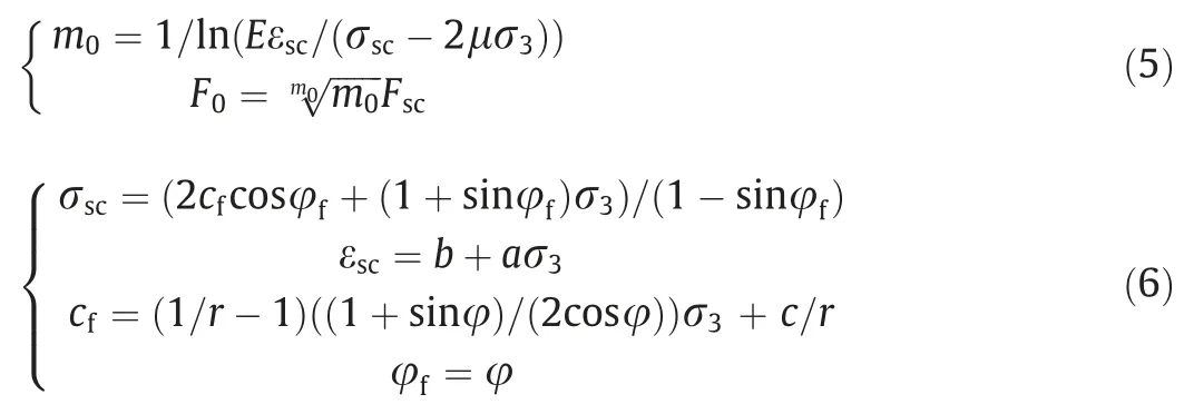
where Fscis the F value corresponding to the rock peak stress point(confining pressure is σ3);σscthe rock peak stress (confining pressure is σ3);εscthe rock peak strain(confining pressure is σ3),which can be calculated based on the triaxial tests;cfand φfthe cohesion and friction angle at peak;a and b the constants,which are obtained by fitting peak strain of rock with confining pressure;and r the ratio of rock yield strength and peak strength,which usually varies between 0.7 and 0.9.
To determine σ1and σ3,a mechanical model based on stress distribution along the working face was established as shown in Fig.5.If the influence of bracket base pressure on the bottom plate is ignored,the overlying load on the bottom plate of the CD segment is 0.The compaction of gangue in the gob increases linearly(DE segment),and the AC segment is the mining pressure influence area.In Fig.5,l1is the distance from the peak stress point to the insitu stress point in the coal seam,l2is the distance from the peak stress point to the coal rib,l3is the distance from the coal rib to the gob stress increment point,and l4is the distance from the in situ stress point in the gob to the gob stress increment point.
To simplify the calculation,the triangular and trapezoidal loads(AB and BC segments) are simplified by q1=(k+1)H/2,and the stress analytical expressions of any point (x0,y0) of the bottom plate under uniform load are obtained as follows [20].

where x1and x2are the starting points of uniformly distributed load,x1<x2;σx,σy,and τxythe horizontal,vertical,and shear stress,respectively;and q1the concentrated load formed in the floor after mining the #4 coal seam.
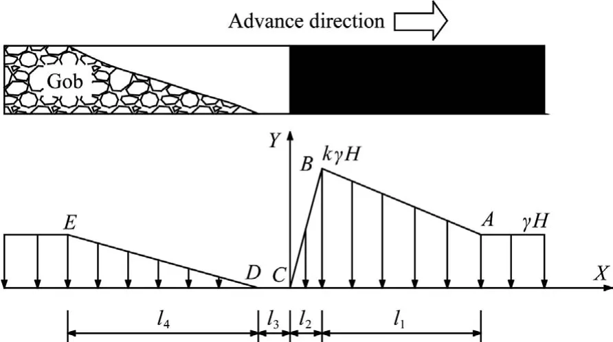
Fig.5.Stress distribution along the working face.
According to Eq.(7),the floor stress in each region in Fig.5 is first solved,and then the analytical results of each section are added together to obtain the overall analytical results of the floor stress distribution.Finally,the maximum and minimum principal stresses (σ1,σ3) can be determined by using Eq.(8).

Based on the strata behaviors of the #42208 working face,the parameters are as follows:l1=50 m,l2=l3=10 m,l4=60 m,k=2.5,E=5.0 GPa,and μ=0.2.The cohesion and friction angle of sandy mudstone at peak point are 2.2 MPa and 28°.Based on the sandy mudstone laboratory test results,a=0.002,b=0.0058 MPa-1,and r=0.75.Substituting these parameters,it can be obtained that the damage factor of interlayer rock strata caused by mining the UCS is D=0.9.
4.Key parameters design of SBB for GER under the gob with CDCS
4.1.Structural mechanics model of GER surrounding rock under the gob with CDCS
Many GER practices indicate that the main stress source of the SBB is from the rotation and subsidence of the overlying roof.The rock strata movement processes of GER under the gob with CDCS include three stages (Fig.6).In the first stage,with the mining of the #5 coal seam and the construction of the SBB,the interlayer rock strata (immediate roof of the #5 coal seam) would break above the #5 solid coal rib ahead of the SBB.In the second stage,the interlayer rock strata bends and the caving zone of the#4 coal seam moves,the main roof of the#4 coal seam breaks firstly above the#5 coal seam solid coal rib.Meanwhile,the load of the SBB still increases.In the third stage,the main roof of the #4 coal seam breaks secondly above the SBB caused by the overburden strata load and the mining of the #5 coal seam.The SBB load would be largest.
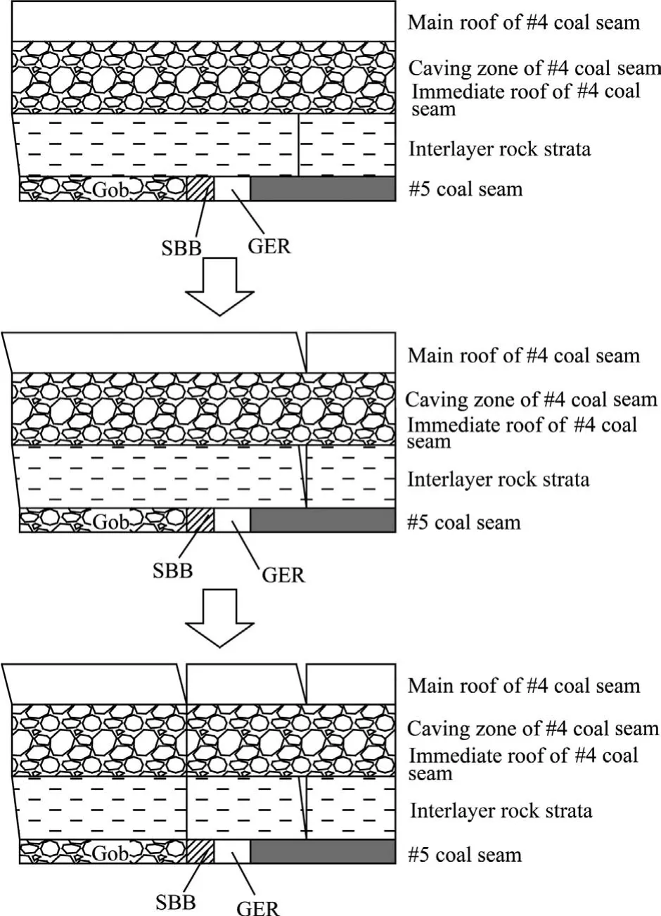
Fig.6.Rock strata movement process of GER under the gob with CDCS.
Based on the roof movement process,the lower rock strata is in a given deformation state,so the structural mechanics model of the GER surrounding rock under the gob with CDCS is established,as shown in Fig.7.
In the early stage,the SBB mainly bears the interlayer rock strata weight,and the weight of caving zone rock strata of the#4 coal seam.Therefore,the minimum SBB support strength,σ1,can be determined by the following Eq.(9).

where lris the retained roadway width;ldthe SBB width;h0the interlayer rock strata thickness;γ0the interlayer rock strata bulk density;hcthe thickness of the caving zone of the #4 coal seam;and γcthe average bulk density of the caving zone of the #4 coal seam.
Therefore,the minimum the SBB width can be determined by Eq.(10).

In the late stage,the SBB mainly bears the main roof weight of the #4 coal seam and its ‘‘given deformation”[26].The main roof rotates and sinks until it fully contacts the gangue.Hence,the roof given deformation at any position (x),Sx,can be obtained by Eq.(11).

where h5is the#5 coal seam thickness;K0the interlayer rock strata hulking coefficient;Kcthe caving zone hulking coefficient;x the horizontal distance away from the rotation point;and l the length of the main roof block,which can be replaced by the periodic weighting pace of the main roof.
Moreover,the compressive deformation of rock strata under the main roof,Δhx,is as follows.

where σxis the compressive stress of the rock strata under the main roof;Ebthe elasticity modulus of the SBB;E0the elasticity modulus of the interlayer rock strata;Ecthe elasticity modulus of the caving zone of the#4 coal seam;Efthe elasticity modulus of the immediate floor of the #5 coal seam;and hfthe immediate floor thickness of the #5 coal seam.
The lower rock mass under the main roof cannot prevent the given deformation of the main roof,so Sx=Δhx.In combination with Eqs.(11) and (12),the compressive stress of the lower rock strata at any position (x) can be calculated by Eq.(13).

Therefore,the compressive stress of the lower rock strata outside of the SBB,σout,is as follows.

When σoutis greater than the support strength of the SBB,the SBB will be fractured.Therefore,σoutshould not be greater than the SBB support strength (σs).The SBB maximum width is determined by Eq.(15).

Based on the mining and geological conditions of the #5210 working face,those parameters can be selected:l=25 m,lr=4.5 m,h4=3.5 m,h5=1.6 m,h0=6 m,hc=12.1 m,hf=1.3 m,Eb=0.25 GPa,E0=8 GPa,Ec=20.15 GPa,Ef=8 GPa,K0=1.15,and Kc=1.3.Moreover,HWQM is applied to construct the SBB.Based on previous laboratory results,when the waterto-cement ratio is 1.5:1.0,the initial setting time is 10 min,and the uniaxial compressive strength of SBB after setting 7 days is 10.36 MPa [27,28].Considering the size effect,selecting σ1=3.0 MPa and σs=8.0 MPa,and substituting these parameters,it can be determined that the maximum SBB width is 1.587 m,and the minimum SBB width is 0.799 m.
4.2.SBB width and strength for GER under the gob with CDCS
4.2.1.Numerical model and simulation processes
In order to determine the SBB width and strength for GER under the gob with CDCS,a plane strain numerical model was employed in FLAC3D[29-31].The dimensions along x,z,and y directions of the present model are 171.7,100.4,and 2.4 m,respectively(Fig.8).The present model along the x direction includes part of the #5210 working face (75 m),SBB,retained roadway (4.5 m),and solid coal seam(50 m).A vertical load(3.8875 MPa,total overlying rock strata weight) is loaded to the top side of the present model.Both the lateral pressure coefficient along the x direction and the lateral pressure coefficient along the y direction are both assumed to be 0.6.The horizontal side is roller constrained,exactly the same constrain as the bottom side.The gob is simulated by the double-yield model.The SBB is simulated by the strain-softening Mohr-Coulomb model [32,33].Meanwhile,the other rock is simulated by the default Mohr-Coulomb model in FLAC3D.
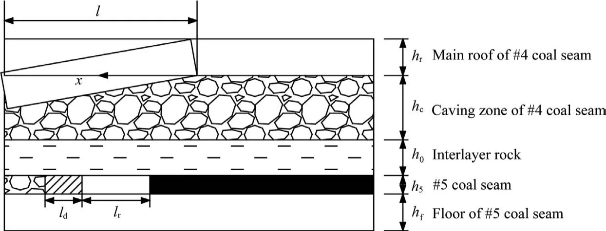
Fig.7.Structural mechanics model of the GER surrounding rock under the gob with CDCS.
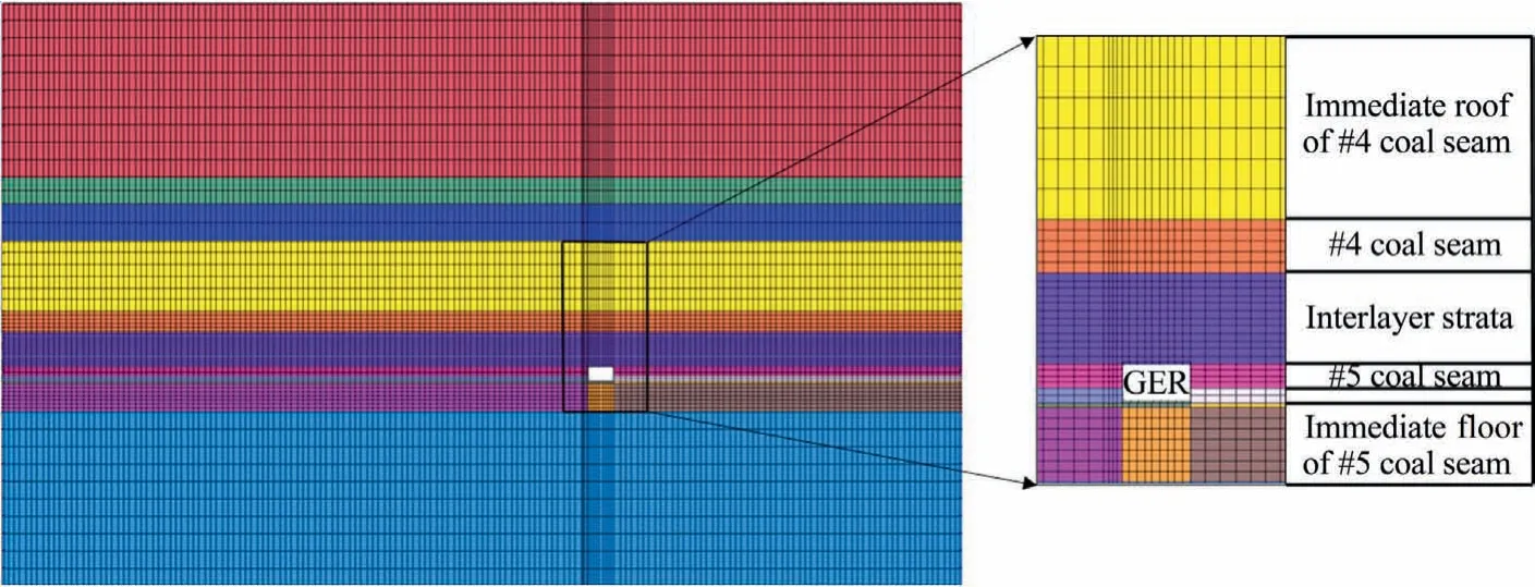
Fig.8.Numerical model.

Table 1 Mechanical parameters of the present model.
Table 1 shows the mechanical parameters in the present model according to the laboratory results [34-36].The whole simulation processes include:(1) establishing the numerical model,(2)calculating the initial stress,(3) retreating the #42208 working face (0-111 m),(4) modeling the excavation of the #5210 track transportation roadway,(5) retreating the #5210 working face,(6) side-roadway backfill and GER,(7) calculating to balance,and(8) changing some factor and repeating the process (1) to (7).
4.2.2.Double-yield model to simulate the gob and calibrations
Many studies indicate that the gob has characterized the mechanical behavior as strain hardening [37-41].Hence,the double-yield model was employed in FLAC3Dto characterize the strain-hardening mechanical behavior of the gob.The calibrations of the double-yield model were conducted according to Eq.(16)(Salamon’s model).

where bgis the gob bulking factor;εgmaxthe maximum gob strain;hcavthe roof caving zone height;hmthe mining height;σcgthe insitu vertical stress above the coal seam;σgthe cap pressure corresponding to the gob strain εg;and Eg0the initial gob modulus.
For the #42208 working face,hmis 3.5 m,while hcavcan be assumed to be 12.1 m (the immediate roof of the #4 coal seam).Then,bgcan be calculated to be 1.188,and εgmaxand Eg0can be counted to be 0.15 and 20.15 GPa,respectively.
Similarly,for the#5210 working face,the total mining height is 5.1 m,while the total height of the caving zone can be calculated to be 24.6 m.bgcan be calculated to be 1.207,and εgmaxand Eg0can be calculated to be 0.17 and 18.23 MPa,respectively.Tables 2 and 3 show the cap pressures of the #4 and #5 coal seams,respectively.
In order to calibrate the reasonability and accuracy of the input mechanical parameters,a series of single-element tests were conducted in FLAC3D.The detailed verification processes can be concerning other papers [37-41].Table 4 shows the final input parameters of the #4 and #5 coal seams.
4.2.3.Determination of optimal SBB width for GER under the gob with CDCS
After the retreating of #5210 working face,the #5210 track transportation roadway is retained with a different SBB width.Fig.9 shows the vertical stress nephogram of the GER surrounding rock concerning SBB width(water-to-cement ratio of the HWQM is 1.5:1.0 in all models).
As shown in Fig.9,the vertical stress in the SBB shapes U-type.The SBB bearing capacity increases and the stability of GER surrounding rock is higher as the SBB width enlarges.When the SBB width is 0.8 m,the SBB vertical stress is around residual stress,which shows that the SBB has been destroyed and the GER surrounding rock would be unstable.When the SBB width is more than 1.0 m,the GER surrounding rock would be stable.
Fig.10 shows the deformation of the retained roadway concerning SBB width.Concerning the SBB width,the influence on the roof-to-floor convergence is large,while the influence on the ribto-rib convergence is small.When the SBB width enlarges from 0.8 to 1.0 m,the roof-to-floor and the rib-to-rib convergence decrease by 74 and 123 mm,respectively.When the SBB width enlarges from 1.0 to 1.2 m,the roof-to-floor and the rib-to-rib convergence decrease by 53 and 54 mm,respectively.When the SBB width enlarges from 1.2 to 1.4 m,the roof-to-floor and the ribto-rib convergence decrease by 85 and 64 mm,respectively.When the SBB width enlarges from 1.4 to 1.6 m,the roof-to-floor and the rib-to-rib convergence decrease by 69 and 54 mm,respectively.Moreover,the roadway section reduction rate could be obtained,as shown in Table 5.When the roadway section reduction rate is calculated,the effective roadway section is determined by the difference between the original size and the maximum roadwaydeformation.The width reduction rate is the ratio of the maximum rib-to-rib convergence to the original roadway width,while the height reduction rate is the ratio of the maximum roof-to-floor convergence to the original roadway height.

Table 2 Cap pressures of the #4 coal seam.

Table 3 Cap pressures of the #5 coal seam.

Table 4 Input parameters of the #4 and #5 coal seams.
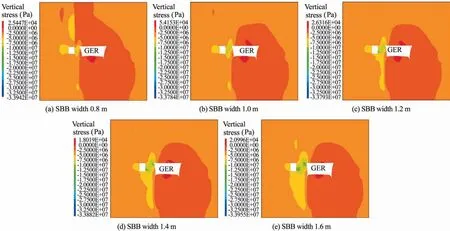
Fig.9.Vertical stress nephogram of GER surrounding rock concerning SBB width.
In conclusion,considering the cost of backfill materials,the SBB width should be as narrow as possible under the conditions of service.When the SBB width is not less than 1.2 m,the vertical stress of the GER surrounding rock is less than the in-situ stress.When the SBB width is greater than 1.0 m,the retained roadway width reduction rate and height reduction rate change less than that of less than 1.0 m.Therefore,it is determined that the optimal SBB width is 1.2 m.
4.2.4.Determination of optimal SBB strength for GER under the gob with CDCS
After the retreating of #5210 working face,the #5210 track transportation roadway is retained with different SBB strength.Tables 6 and 7 show the mechanical parameters and input parameters of the strain-softening Mohr-Coulomb for SBB in FLAC3D,respectively.
Fig.11 shows the vertical stress nephogram of the GER surrounding rock concerning SBB strength (SBB width is 1.2 m).As shown in Fig.11,with the increase of the strength of the SBB(water-to-cement ratio of HWQM decreases),the vertical stress in the SBB increases,the vertical stress in the solid coal rib decreases,and the position of the maximum vertical stress in the solid coal rib moves away from the solid coal rib.
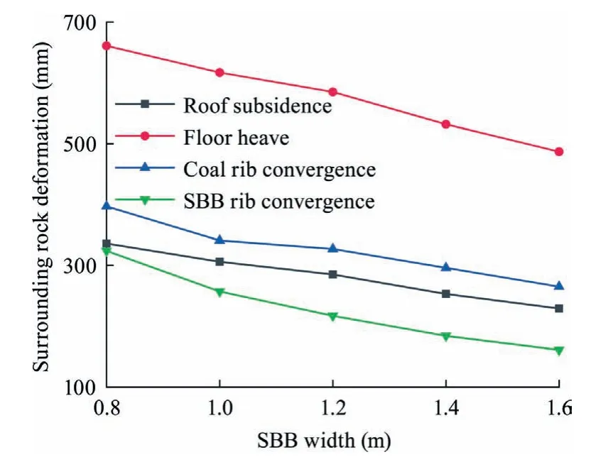
Fig.10.Surrounding rock deformation of the retained roadway concerning SBB width.

Table 5 Section reduction rate with respect to different SBB width.

Table 6 Mechanical parameters of Mohr-Coulomb strain-softening model for SBB.
Fig.12 shows the GER surrounding rock deformation concerning water-to-cement ratio of HWQM.As the water-to-cement ratio of HWQM increases (the SBB strength decreases),the GER surrounding rock deformation increases,especially the SBB rib deformation and roof subsidence.When the water-to-cement ratio of HWQM increases from 1.5:1.0 to 2.0:1.0,the roof-to-floor and the rib-to-rib convergence increases by 221 and 192 mm,respectively.When the water-to-cement ratio of HWQM increases from 2.0:1.0 to 2.5:1.0,the roof-to-floor and the rib-to-rib convergence increases by 93 and 32 mm,respectively.Moreover,the simulation results demonstrate that when the water-to-cement ratio of HWQM is 2.0:1.0 and above,the main roof of the#4 coal seam cannot be cut off by the SBB along the gob.As a result,the SBB can only be forced to fit the subsidence and rotation movement of the main roof of the #4 coal seam.
Similarly,considering the cost of backfill materials,the waterto-cement ratio of HWQM should be as large as possible under the conditions of service.According to the numerical simulation,it is determined that the water-to-cement ratio of HWQM is 1.5:1.0.
5.Engineering trial tests
5.1.GER technical schemes for #5210 track transportation roadway
GER technical schemes for#5210 track transportation roadway include in-roadway support technology,side-roadway supporttechnology.The in-roadway support technical scheme is shown in Section 2.The side-roadway support technology includes constructions of the SBB and advance break support schemes.

Table 7 Input parameters of SBB in FLAC3D.

Fig.11.Vertical stress nephogram of the GER surrounding rock concerning SBB strength.
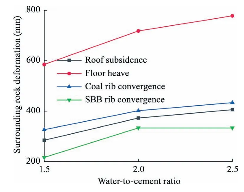
Fig.12.GER surrounding rock deformation concerning SBB strength (water-tocement ratio of HWQM).
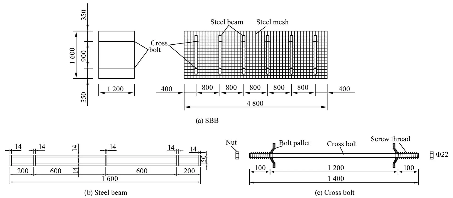
Fig.13.SBB construction sketch (unit:mm).
5.1.1.Constructions of the SBB
According to the previous study,the SBB width is determined to be 1.2 m,and the water-to-cement ratio of HWQM is 1.5:1.0.The cycle length of the SBB is equal to the footage of each production shift of the #5210 working face (4.8 m).The backfill height of the SBB is equal to the mining height(1.6 m).To improve the bear capacity of the SBB,cross bolts with Φ22 mm in diameter and 1.4 m in length are employed inside the SBB.Meanwhile,steel mesh made of 6.5 mm round steel in diameter is used to wrap the side-roadway backfill bag to improve the shape,as shown in Fig.13a.Two rows of cross bolts along the retained roadway are set up with a space of 0.9 m,which are connected by steel beams with 1.6 m in length.Fig.13b shows the steel beams with a space of 0.6 m are made of 14 mm round steel in diameter.Fig.13c shows the cross bolts are made of 22 mm round steel in diameter,with 100 mm screw thread at both ends.
5.1.2.Advance break support schemes
To prevent roof caving,keep the integrity of the roof above the backfill area and reduce backfill cost,an advance break is excavated along the retained roadway.The advance break is supported by rock bolts,anchor cables,and steel mesh [42-46].The specific scheme is as follows:the advance break is excavated along the roof,and the width,depth,and height of the advance break are 4.8,3.0,and 1.6 m,respectively.Four rows of Φ22 mm×2.0 m rock bolts along the strike direction are arranged with a space of 0.8 m.A row of Φ18.9 mm × 5.2 m anchor cables along the strike direction are arranged with a space of 1.6 m.The roof is also wrapped with steel mesh.The support schemes of the advance break are shown in Fig.14.
5.1.3.In-roadway roof reinforcement support
To decelerate the impact of the advance mining pressure on GER and ensure that the retained roadway reaches a good technical index,it is necessary to carry out advance roof reinforcement support.Temporary reinforcement support measures in the retained roadway are as follows:four rows of single hydraulic props along the strike direction are equipped with type steel beam and iron shoes with a space of 1.0 m.The detailed support measures are shown in Fig.14a.
5.2.Engineering tests effect
5.2.1.GER surrounding rock deformation when mining the #5210 working face
Fig.15a shows the GER surrounding rock deformation behind the active #5210 working face.The roof-to-floor convergence is greater than the coal rib-to-SBB rib convergence,and the difference in value is especially obvious behind the active #5210 working face,with a difference of 316.9 mm in the final convergence.Surrounding rock deformation characteristics of the retained roadway include three stages:(1) Stage I (0 to -20 m):As the monitoring point is relatively near the active #5210 working face,the relative movement of the roof and floor is relatively gentle,with a relatively small amount of movement;(2) Stage II (-20 to -100 m):Due to the impact of periodic pressure of the #5210 working face and full mining,the overlying strata of GER are violently active,and the upper rock strata broke twice above the solid coal top and outside the SBB,resulting in severe deformation of surrounding rock;and(3)Stage III(after-100 m):GER surrounding rock deformation races to be changeless.The cumulative convergence is 421.4 mm on coal rib-to-SBB rib and 813.5 mm on the roof-to-floor.Among them,the roof subsidence convergence is 205.2 mm,the floor heave convergence is 608.4 mm,the SBB displacement is 100 mm,and the solid coal rib displacement is 323.4 mm.
5.2.2.Roof separation characteristics when mining the#5210 working face
Fig.15b shows roof separation characteristics when mining the#5210 working face.Roof separation characteristics of the retained roadway include two stages:(1)Stage I(0 to-40 m):As surrounding rock stress is readjusted,the roof separation is large;and (2)Stage II (after -40 m):The stress adjustment basically rebalances,and the roof separation remains unchanged and enters a stable state.
The maximum separation convergences of the shallow and deep base points are 41 and 18 mm,respectively.The separation convergence of the retained roadway roof is relatively small,less than the permissible extensive quantity of the rock bolt and anchor cable.It indicates that the GER roof has been controlled effectively by means of the support system combined high strength rock bolts with anchor cables.
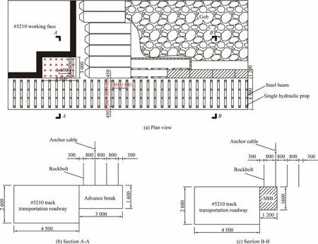
Fig.14.Support schemes of the advance break (unit:mm).
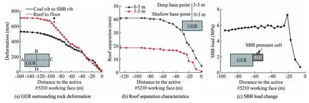
Fig.15.GER monitoring results when mining the #5210 working face.
5.2.3.SBB load characteristics when mining the #5210 working face
Fig.15c shows SBB load characteristics when mining the#5210 working face.SBB load characteristics of the retained roadway include three stages:(1)Stage I(0 to-10 m):SBB load is less than 2.0 MPa;(2)Stage II(-10 to-40 m):As the roof sinks and rotates,the SBB load begins to increase sharply,reaching a maximum of 7.5 MPa;and (3) Stage III (after -40 m):The SBB load is stable at 5.3 MPa.
It can be seen from Fig.15c that the SBB constructed with HWQM has a high resistance increasing speed and bears a high load.The SBB effectively keeps the stability of the GER roof and adjusts to the rotation and sink of the main roof of the #4 coal seam,prevents the retained roadway roof from separating,and effectively controls the GER surrounding rock deformation.Fig.16 shows the in-situ GER effect.
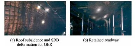
Fig.16.In-situ GER effect.
6.Conclusions
Multi-seams mining with close distance coal seams (CDCS)widely exists in China.GER technology plays an important role to help the sustainable development of the coal mining.How to mine out the valuable and rare CDCSs under the gob more safely and efficiently not only affects the coal recovery rate but also affects the sustainable development of energy resources.In this paper,control technology and surrounding rock stability mechanisms of GER under the gob with CDCS are present.The main conclusions include:
(1) The maximum failure depth of the #4 coal seam floor rock strata is obtained by plastic slip theory,which indicates that the interlayer rock strata,#5 coal seam,and 0.94-m thick immediate floor of the #5 coal seam are damaged.Damage factor of interlayer rock strata due to mining the #4 coal seam is determined to be 0.9 by establishing a continuum damage model.
(2) A structural mechanics model of GER surrounding rock under the gob with CDCS is established to obtain the width of side-roadway backfill body(SBB)and strength parameters by theoretical evaluations.Moreover,numerical simulations by FLAC3Dare used to study the relationship between the surrounding rock stability,the SBB width,and the SBB strength (water-to-cement ratio of high water quicksetting material (HWQM)).The optimal SBB width and water-to-cement ratio of HWQM are 1.2 m and 1.5:1.0,respectively.
(3) Engineering trial tests carried out at the #5210 track transportation roadway of the Xingwu Colliery indicate that GER control technology including the high-strength rock bolts and anchor cables formed as in-roadway support,advance break supported by rock bolts,anchor cables,and steel mesh to provide safe construction space,SBB constructed with HWQM enhanced with cross bolts,steel beam,and steel mesh,single hydraulic props combined with steel beams formed as in-roadway roof reinforcement support,effectively controlling the GER surrounding rock deformation.
Acknowledgements
The authors acknowledge the financial support from the National Natural Science Foundation of China (Nos.51804111,51974117,51904102,and 52074117),Natural Science Foundation of Hunan Province (No.2020JJ5194),and the Postgraduate Scientific Research Innovation Project of Hunan Province (No.CX20200991).
杂志排行
矿业科学技术学报的其它文章
- Development of ensemble learning models to evaluate the strength of coal-grout materials
- An updated empirical model for ground control in U.S.multiseam coal mines
- Study on seepage and deformation characteristics of coal microstructure by 3D reconstruction of CT images at high temperatures
- Drilling signals analysis for tricone bit condition monitoring
- The influence of borehole arrangement of soundless cracking demolition agents (SCDAs) on weakening the hard rock
- Numerical assessment of the influence of former mining activities and plasticity of rock mass on deformations of terrain surface
