Smart Meter Development for Cloud-Based Home Electricity Monitor System
2021-01-23YeongChinChenSunnengSandinoBerutuYueHsienWang
Yeong-Chin Chen | Sunneng Sandino Berutu | Yue-Hsien Wang
Abstract—A cloud-based home electricity data-monitoring system, which is based on an Arduino Mega controller, is proposed for monitoring the electricity consumption (electrical power) and power quality (PQ) in home.This system is also capable of monitoring the fundamental frequency and supply-voltage transients to ensure that the appliances operate in a safe operation range.The measured data (voltage and current) are transmitted through a WiFi device between the Arduino controller and server.The transmission control protocol (TCP) server is set up to acquire the high-data transmission rate.The server system immediately displays the calculated parameters and the waveform of the acquired signal.A comparison with a standard measurement device shows that the proposed system, which can be built at a low cost, exhibits the same functions as a factory product.
1.lntroduction
According to the statistics of Taipower, 24000 high-voltage consumers, who currently account for 60% of the total electricity consumption in Taiwan, have installed smart meters.However, general-public users are not willing to install these meters due to the high cost and need to send an application to Taipower before the installation.The procedures are complicated and involve many communications problems.The government expected an installation[1]of 200000 smart meters by September 2018.However, only 150000 were completed.In recent years,the power deficit has become enormous during summer.This problem results in power-supply units surging,electricity charge rate issues, power waste issues, and even worse, the endless argument on the non-nuclear power-supply issue.However, since the power output cannot be increased immediately, the electrical power management for the efficient use of electricity has become an extremely important issue.
The Internet of things (IoT)[2]is a revolutionary technology capable of achieving sensing integration as well as communications capabilities between common devices.IoT has enabled various devices to be used for monitoring important electrical, physical, and environmental parameters.This information is then used to analyze, identify, and solve various problems related to everyday life[2].IoT has enabled power-monitoring devices to assist in solving this problem by providing valuable information on electricity consumption and power quality (PQ)[3], which includes the measurements of the fundamental frequency, the root mean square (RMS) of voltage, and the power factor (PF).In this way, the purpose of power savings and power safety can be achieved.
Using the IoT smart power meters, the power consumption of various electrical appliances can be automatically measured, logged, and analyzed.This will also help in identifying major power consumers and promoting energy awareness in society.In this research, a power-monitoring system is proposed, which is based on a low-cost Arduino controller[4]and some electricity sensors with embedded IEEE 802.11 (WiFi) wireless communications.The instantaneous power signal (voltage and current) is wirelessly transmitted to a remote server for storage and analysis.A hypertext preprocessor (PHP) web program, which is developed to analyze the power signal data,simultaneously displays the analysis results, electrical power energy, electrical PF, and fundamental frequency[5]on the browser’s window.The user can retrieve statistically analyzed data stored on the server, using a computer or a smartphone over the Internet.An early warning system is also provided.This system sends a warning alarm to remind the user of a problem with the equipment when the electrical performance is out of the specified range.As an advanced future application, the server could also provide a big-data query and convert the queried degree into a form, with which the users can analyze the electricity consumption, thus improving the power-usage strategy of users.
The rest of the paper is organized as follows.The research methods and materials are described in Section 2.The results and conclusion are presented in Sections 3 and 4, respectively.
2.Methods and Materials
2.1.Methods
In this paper, the proposed system is schematically illustrated in Fig.1.
Initially, the alternating-current (AC) voltage is connected to ZMPT101B[6]and transmitted to the ACS712[7]socket to measure the current.Then, the signal is processed by an analog-to-digital converter(ADC)—Arduino[8].By employing the universal asynchronous receiver/transmitter (UART) transmission,the signal is transmitted to a node micro-controller unit(NodeMCU)[9]device based on ESP 8266 WiFi.This device transfers data, using a transmission control protocol (TCP)[10]connection, to a server which is built with an open source programming language from Google (GO)[11].Finally, the power consumption performance is monitored by a multiple-platform display.In this work, the signal’s frequency is detected and calculated by using the zero-crossing algorithm[5].Then, the Fourier series algorithm[5]is applied to filter out the noise and high harmonics.RMS[12]is the effective value, which determines the electricity variation.PF is determined by the phase between the measured voltage and current signals.The power consumption is also calculated by using the RMS values of the voltage and current.The monitoring system flowchart is shown in Fig.2.Finally, the results produced are compared with those obtained by a power measurement standard device (HIOKI PW3360)[13].
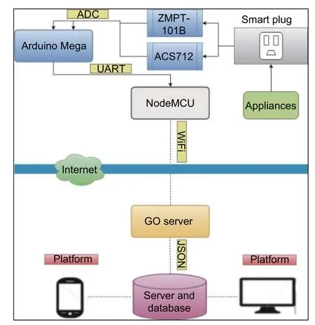
Fig.1.Proposed system architecture.
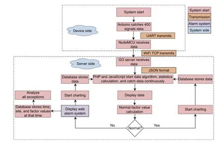
Fig.2.Flowchart of the proposed home electricity monitoring system.
2.2.ZMPT101B Voltage Sensor
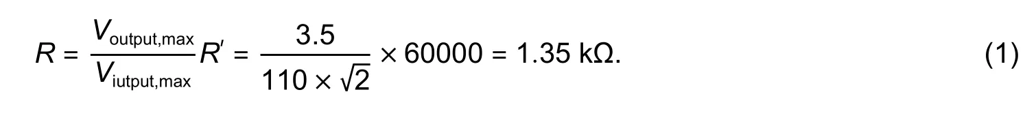
This sensor converts the AC voltage of 110 V to 220 V into an acceptable value range for the Arduino controller.In Fig.3, the variable resistor (r) adjusts the AC-input voltage.In this way, a user can manually vary this voltage.The output voltage can be adjusted to an amplitude range of 0 to 5 V, which is acceptable by the Arduino controller.The rated operating current of ZMPT101B is between 1 mA and 2 mA.When the equivalent voltage is ≤100 V, the current isI=2 mA,whereas when the voltage is ≥ 220 V, the current is usually 1 mA ≤I≤ 2 mA to reduce the power consumed by the resistor.Based on the application guide of ZMPT101B[14], the variable resistor ratio should be adjusted according to the experimental requirements.In this work, the current limiting resistor (R′) is set to 60 kΩ (110 V/2 mA) to make the input current less than 2 mA.If the maximum output voltage is set to 3.5 V, the sampling resistorRcan be obtained from

Fig.3.Schematic diagram of the ZMPT101B sensor voltage.
2.3.ACS712 Current Sensor
The Arduino controller receives only the output voltage.ACS712[7]converts the input current into voltage using a formula to obtain the real current value of a home appliance[8].The output voltage (Vout) of ACS712 as a linear function of the actual current (Ip) is shown in Fig.4.
According to Fig.4, the output voltage can be written as follows:
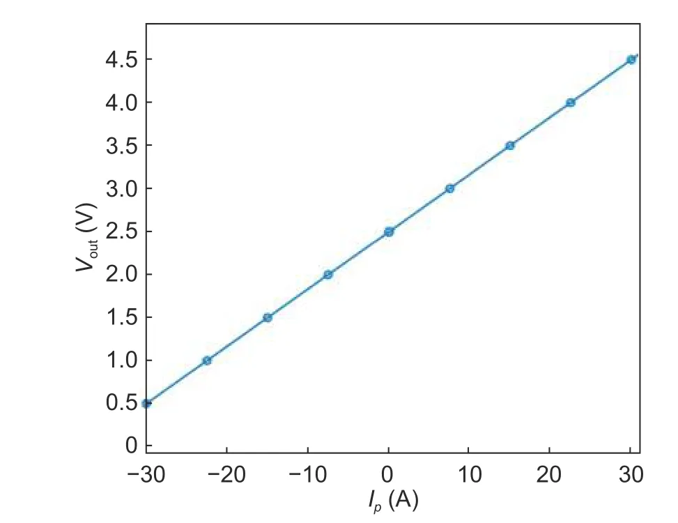
Fig.4.Graph of the output voltage vs.input current.
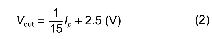
where −30 A ≤Ip≤30 A.The Arduino ADC resolves 1 bit to 10 bits (0 to 1023), and the Hall-current sensing module can be used to measure the current.As the Arduino acquires a valuev, which is the output voltage of the current sensor, the sensing current can be obtained as follows:
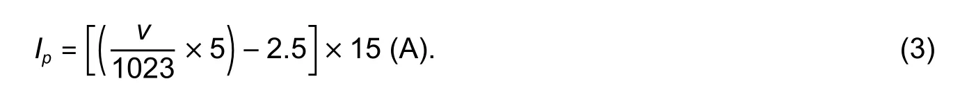
When there is no current input, i.e.Ip=0, the component itself will produce an output voltage of 2.5 V to the Arduino controller.
2.4.Sampling Frequency Determination
The Arduino data-acquisition approach uses the analogRead(0) instruction to convert analog information into digital information (ADC module).The chip used in the Arduino is the ATMega chip[15].Its oscillation frequency is 16 MHz, and its internal ADC prescaler select (ADPS) bit setting is shown in Table 1[16].
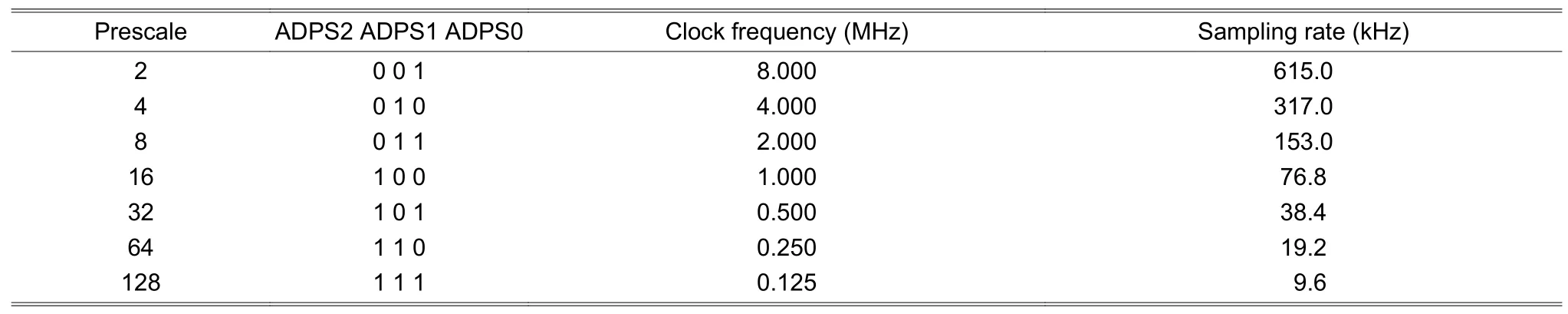
Table 1:Prescaler setting for the Arduino ADC
For the 16-MHz Arduino, if the default prescaler is set to 128 (16 MHz/128=125 kHz) and the implementation of an ADC function requires 13 cycles, then the sampling rate in the Arduino ADC module could be theoretically up to approximately 9.62 kHz (125 kHz/13=9.615 kHz).If the sampling accuracy is taken into account, the sampling frequency needs to be maintained more than ten times the frequency of the measured signal.Because the fundamental frequency of power signals is 60 Hz, and when multiplied by 25, the frequency of the harmonic wave is only 1.5 kHz.Thus the Arduino ADC module can sufficiently meet the requirement of this study.
The estimation accuracy of the following zero-crossing algorithm can be maintained by tuning the Arduino ADC sampling frequency at 3 kHz.This can be achieved by inserting a time-delay instruction code to modulate the sampling rate according to the specifications.If the sampling rate is set to 3 kHz, the time slot between two adjacent samples will be 333 μm.Since the signal from the voltage and current sensors is received sequentially for each ADC loop, it will spend 104 μm between the adjacent voltage and current acquired data with the ADC sampling rate of 9.6 kHz.In our experiment, the voltage and current signals are assumed to be acquired at the same time that the prescaler’s setting is switched to 16 to make the ADC sampling rate equal to 76.8 kHz.This means that the ADC time delay reduces to 15 μs, whereas the voltage and current phase error of the power signal is reduced from (60 Hz/9.6 kHz)×360=2.25 degrees to(60 Hz/76.8 kHz)×360=0.28 degrees.
The sampling frequency was evaluated by using a standard sinusoidal wave of frequency 1 kHz in the Arduino ADC module, and the delay times in the ADC loop were set to 150 μs, 200 μs, 250 μs, 300 μs, and 350 μs,respectively.The corresponding sampling points per period obtained with the zero-crossing algorithm were 5.085 points, 4.013 points, 3.315 points, 2.823 points,and 2.459 points, respectively.Since a frequency of 1 kHz was used in the Arduino ADC module, the sampling frequencies were 5.085 kHz, 4.013 kHz,3.315 kHz, 2.823 kHz, and 2.459 kHz, respectively.Using the linear regression theorem[17], the relationship between the programmed delay time (X) and sampling period (Y) was obtained as follows:
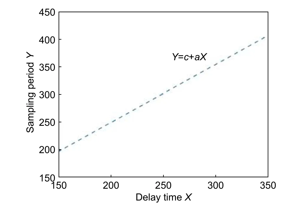
Fig.5.Relationship between the delay time (X) and sampling period (Y) in the Arduino ADC module.
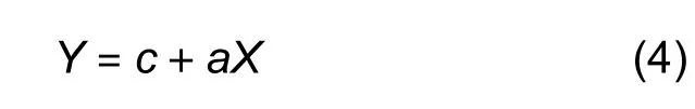
wherec=39.12601 anda=1.050209.
In this work, the sampling frequency was set to 3 kHz according to the relationship between the delay time (X) and sampling period (Y) in Fig.5.The Arduino ADC delay time should be set to 280 μs.
2.5.RMS Current Calculation
RMS[12]is a mathematical method used to define the effective direct current (DC) value of a time-varying sinusoidal waveform (AC power), which produces the same heating effect as the equivalent DC power.For a sinusoidal waveform, which hasmequal portions per cycle, its RMS value can be calculated as follows:
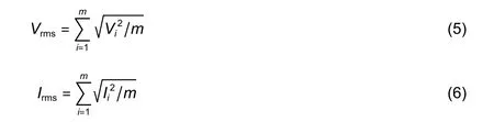
whereViis the amplitude of the voltage at pointi,Iiis the amplitude of the current at pointi, andmis the sampled points per cycle.
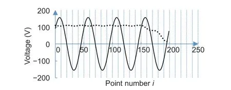
Fig.6.Voltage signal and its RMS value obtained using the window-sliding method.
In our experiments, the 4-cycle voltage signal(200 points) with 50 equal portions per cycle, which is acquired by the Arduino ADC, is shown in Fig.6, and the variation of RMS values (Vrms,slide(i)) of this signal is also shown in Fig.6.In addition, RMS can be utilized to measure the PQ disturbances related to the voltage magnitude variations, such as the voltage drop, voltage sag, voltage swell, under-voltage, over-voltage, and interruption.
The variation of this signal’s RMS values is calculated using the window-sliding method.In this method, each RMS value is calculated from the values in the window, and the window frame is sequentially slide by 1 point until the number of points(50 points) is less than the sampling points per cycle.The window-sliding RMS method for the voltage and current variations can be expressed as follows:
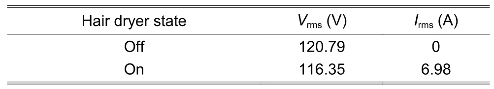
Table 2:RMS values of voltage and current
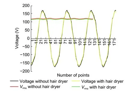
Fig.7.Voltage waveform and variation of its RMS value when the hair dryer is turned on and off.
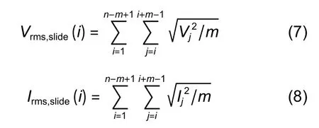
wherei=1,2,…,n−m+1;j=i,i+1,…,i+m−1;n=200 is the number of total points of the acquired signal, andm=50 is the total number of sampled points per cycle.
Assuming a hair dryer with the specified power consumption of 8 W as a load, the voltage and current RMS values when the hair dryer is turned on and off are listed in Table 2.
By implementing the formula in (2), (3), (7), and (8),the voltage and current signals and the variations of their RMS values are shown in Figs.7 and 8,respectively.The experimental results show a current value close to zero as the hair dryer is turned off.TheIrmsvalue increases to 6.98 A, when the hair dryer is turned on.However, the voltage signal exhibits a small deviation when the hair dryer is turned on.
2.6.Fourier Series Algorithm
The voltage and current signals include noise.The harmonic signal involved will distort them from a pure sinusoidal wave.As a result, the accuracy of the fundamental frequency and phase angle determination might be affected.
The acquired power signal generally can be presented by a discrete Fourier series (DFS)[5],[16],expressed as follows:
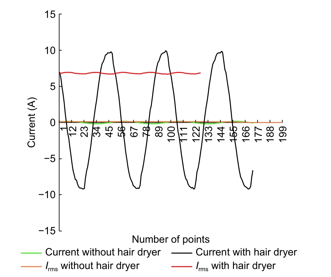
Fig.8.Current waveform and variation of its RMS value when the hair dryer is turned on and off.

AndA(i) andB(i) can be expressed as follows:
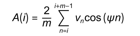
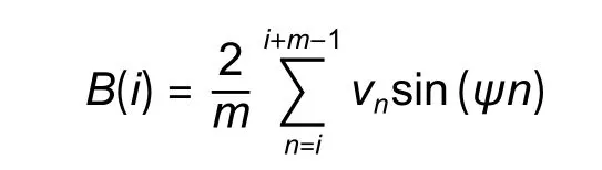
wherevi istheith sample value of the signal,mis the number of samples obtained by a fundamental frequency period, andψ=(ωaTa)/m=2π/mwithωabeing the angular frequency of the fundamental frequency andTabeing the sampling period.
Practically, the cosine and sine signals in (7) can be represented as a vector with the length ofm:
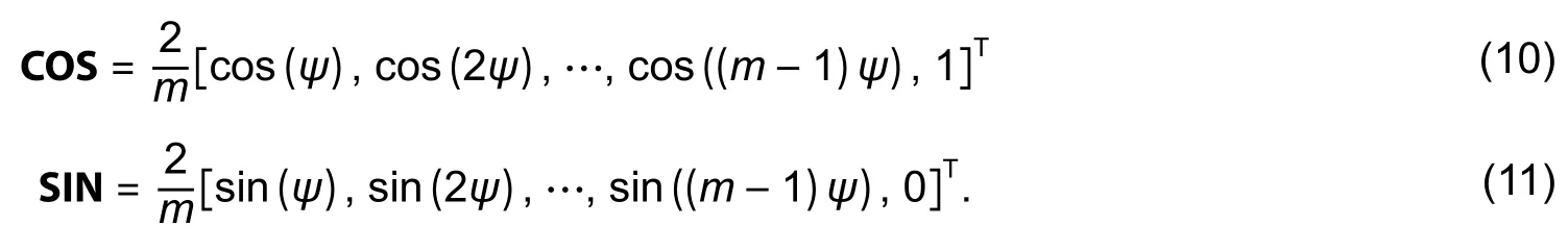
The vector of signal samples is expressed as follows:

Using an auxiliary vector of COS and SIN, (11) can be calculated using only multiplication and addition without any trigonometric calculation.Thus, the calculations become very simple.After each sampling, the sampling points should be re-arranged as follows:

Therefore, by moving the data window, the signal sample values are considered as scalar signal processing.For each data set in the data window, the corresponding cos(A(t)) and sin(B(t)) components in (7) can be calculated.The voltage and current signals with and without applying the Fourier series filter are shown in Fig.9.It can be observed that the loading effect of the device tends to induce more noise to the power signal.The Fourier series algorithm is capable of filtering out the noise and harmonics and produces a smooth fundamental frequency signal for the frequency and phase angle determination.
2.7.Zero-Cross Algorithm
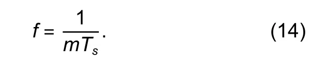
The voltage frequency indicates whether a power line reaches an equilibrium state between the supply and demand.Therefore, the frequency is a very important indicator of the reliability, safety, and economy of the power line system.In this paper, the zero-cross algorithm[17]is applied to evaluate the voltage frequency provided by Taipower.It also provides information, which allows users to ensure PQ.The real frequency can be determined by calculating the number of points (m) in a cycle shown in Fig.10.This number is divided by the constant sampling time slot (Ts) of the Arduino ADC, and then the frequency is calculated by reversing the cycle timeT=mTs, as follows:
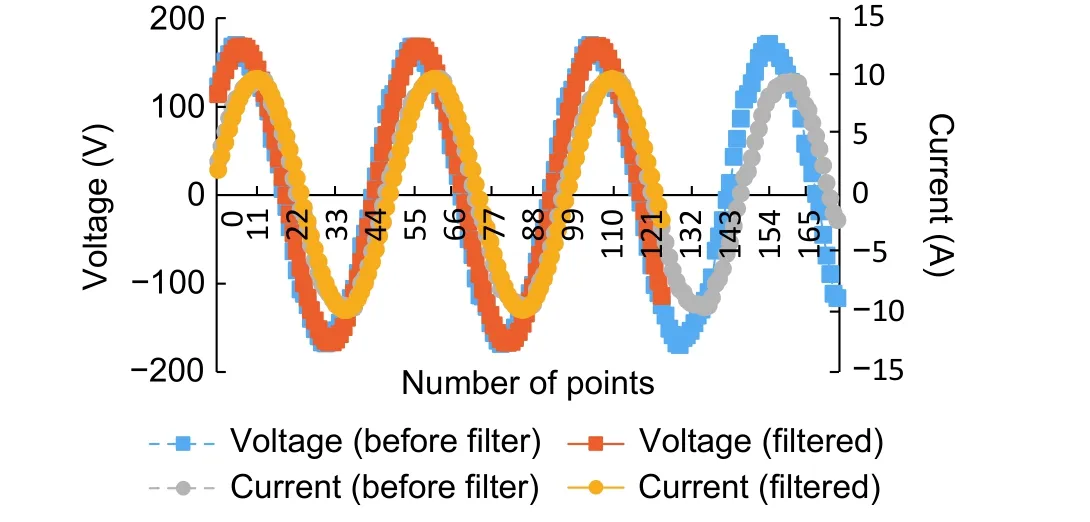
Fig.9.Power signal when a hair dryer is used as the load and the Fourier series algorithm filters out the noise.
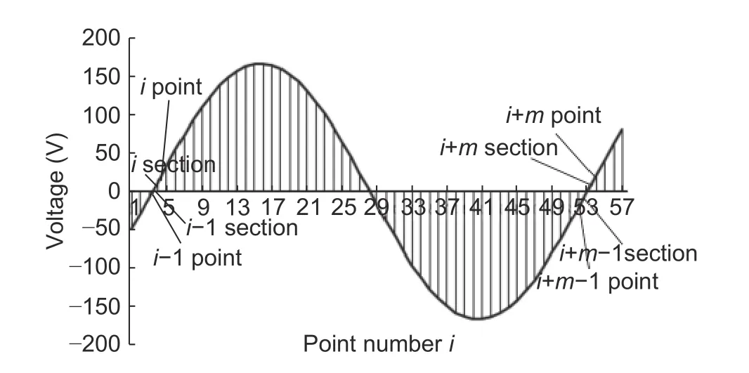
Fig.10.Graph showing the number of points in a cycle.
However, since the waveform is divided by the constant sampling rate, there are two small segments between the zero points of a cycle that cannot be counted and are included in the points measured.As shown in Fig.11, the segmentδ2is in the right portion of the pointi−1 to pointiandδ3in the left portion of the pointi+mto pointi+m+1, which is not an integer point.For the accurate measurement, the cycle time of this sampled signal must be expressed as follows:

whereTis the period of the sampled signal,mAis the accurate number of sampling points between the zero points of one cycle, andTsis the sampling time slot of the Arduino ADC.
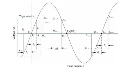
Fig.11.Schematic diagram for the zero-cross algorithm.
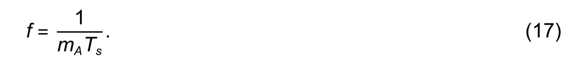
Using a similar triangle principle,mAcan be expressed as

whereyi−1,yi,yi+m−1, andyi+mare the magnitudes of the (i−1)th,ith, (i+m−1)th, and (i+m)th points,respectively.The accurate frequency of the signal can be estimated as
2.8.PF Calculation
The PF algorithm calculates the amplitude of the phase difference between two waveforms[18].In electrical engineering, PF of an AC electrical power system is defined as the ratio of the real power absorbed by the load to the apparent power flowing in the circuit, and it is a dimensionless number in the closed interval of [−1, 1].This study aims at notifying users of the existence of a low-PF problem as well as understanding the performance of electrical appliances, so as to consider whether it is necessary to replace or maintain the equipment.When PF is too low, the current required to generate the same output power increases.As the current increases, the energy loss in the circuitry increases, and the damage or the probability of the wires and associated electrical equipment getting burned increases.
In this work, if the phase between the voltage and current waveforms is calculated from a sample point,which is located in the valley of the waveforms, at least one point-count error between the two waveforms exists.This is because the sample point is not exactly located in the valley of both the voltage and current waveforms, as shown in Fig.12.
Since the number of sampling points per cycle is close to 50, one point error of the points counted between two valleys will result in a phase error of approximately 7.2 (360/50) degrees.The accuracy can be improved by applying the zero-cross algorithm to determine the location of the first zero point of the voltage and current and calculate PF as follows:
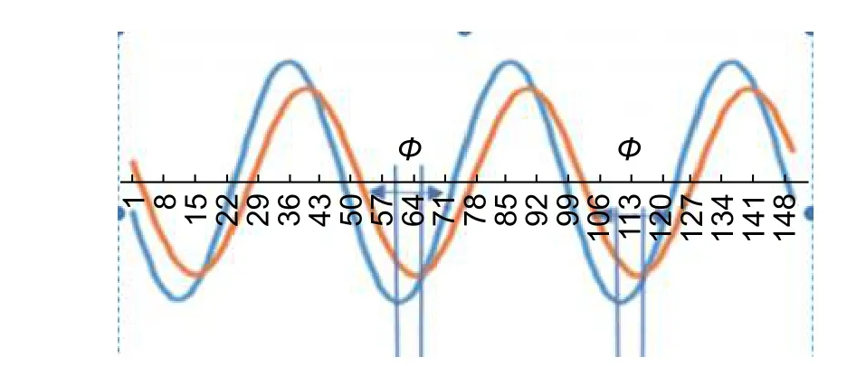
Fig.12.Schematic for phase determining.
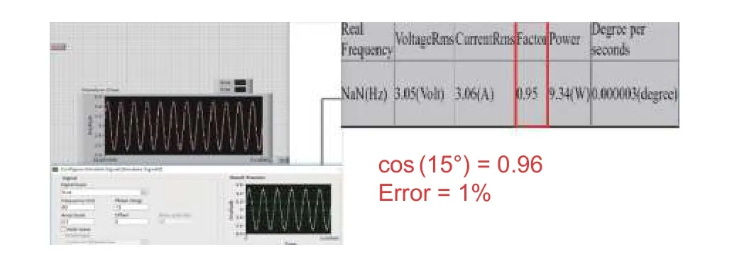
Fig.13.15-degree phase difference test.
whereΦis the phase in degrees;NVandNIare the numbers of points at the zero point for the voltage and current, respectively.
If the phase difference exceeds 90 degrees, the voltage and current directions are at 90 degrees apart,and only the phase difference is deducted by 180 degrees, so that the two waveform directions can be corrected.
In this work, a LabVIEW program and a data acquisition (DAQ) device[19](National Instruments (NI myDAQ)) are adopted to generate two signals with a phase difference of 15 degrees, 45 degrees, and 60 degrees, respectively.LabVIEW is multi-pin output,which produces a waveform angle, set by the user.The accuracy is quite high and can be used in the experiment.In this experiment, two waveforms are produced, one of which is set to 0, so that the phase difference is known when designing the angle of another waveform.The experimental results are shown in Figs.13, 14, and 15, respectively.The error range is approximately 1% to 3%.The PF accuracy of more than 5% is less reliable.The PF accuracy of less than 3%is an acceptable normal error, which proves that the system’s PF calculation is accurate and acceptable.
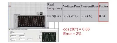
Fig.14.30-degree phase difference test.
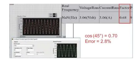
Fig.15.45-degree phase difference test.
2.9.TCP Server Setup
The fast network transmission is required to transfer the timely power signal and calculate the data per second.NodeMCU is used as TCP to transfer data to the server.NodeMCU includes the officially recognized WiFi transmission module of the Arduino.It is several times faster than the Arduino’s external WiFi component and suitable for transferring large amounts of data.NodeMCU has only one ADC interface and cannot measure the voltage and current values simultaneously.Thus, the Arduino’s UART transmission method[8]is used to transfer the voltage and current data to NodeMCU.A diagram of the data transmission process is shown in Fig.16.
The GO language server is set up to process the data transmitted by NodeMCU and stores the data in a JSON file format for the PHP server.In the UART transmission, if the data transmitted are received as an integer type, the digital ASCII code and the blank character ASCII will be displayed.If a character type is received, the character of the digital value can be directly obtained.
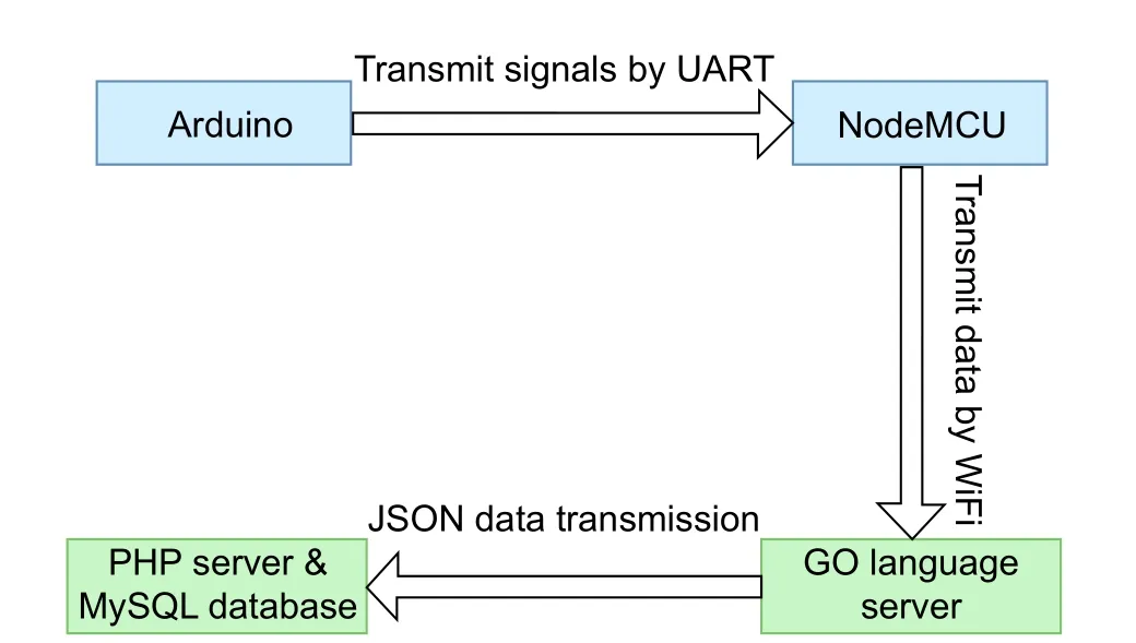
Fig.16.TCP server data transmission process.
In this experiment, the NodeMCU WiFi transmission data method used the high-bit and low-bit transmission to reduce the burden of WiFi transmission.For example, the number 713 is represented by binary digits as 0010 1100 1001.The high-bit part is 0010 and the low-bit part is 1100 1001.The low-bit part is extracted using the AND logical operator by comparing 0xFF values.Finally, the data are stored in an array and then transmitted to the GO server.Using this method, the size of the 713 integer type—4 bytes can be reduced to 2 bytes.This increases the WiFi transmission speed and reduces the burden.According to the example, the high-bit decimal value is 2, whereas the low-bit decimal value is 201.The high-bit and low-bit parts are stored in the server.The original value in the client side can be obtained by calculating (256×the high-bit+the low-bit).Based on this example, the result is 713.The transmission data process is shown in Fig.17.By implementing this method, the WiFi transmission speed can reach more than one thousand data per second.
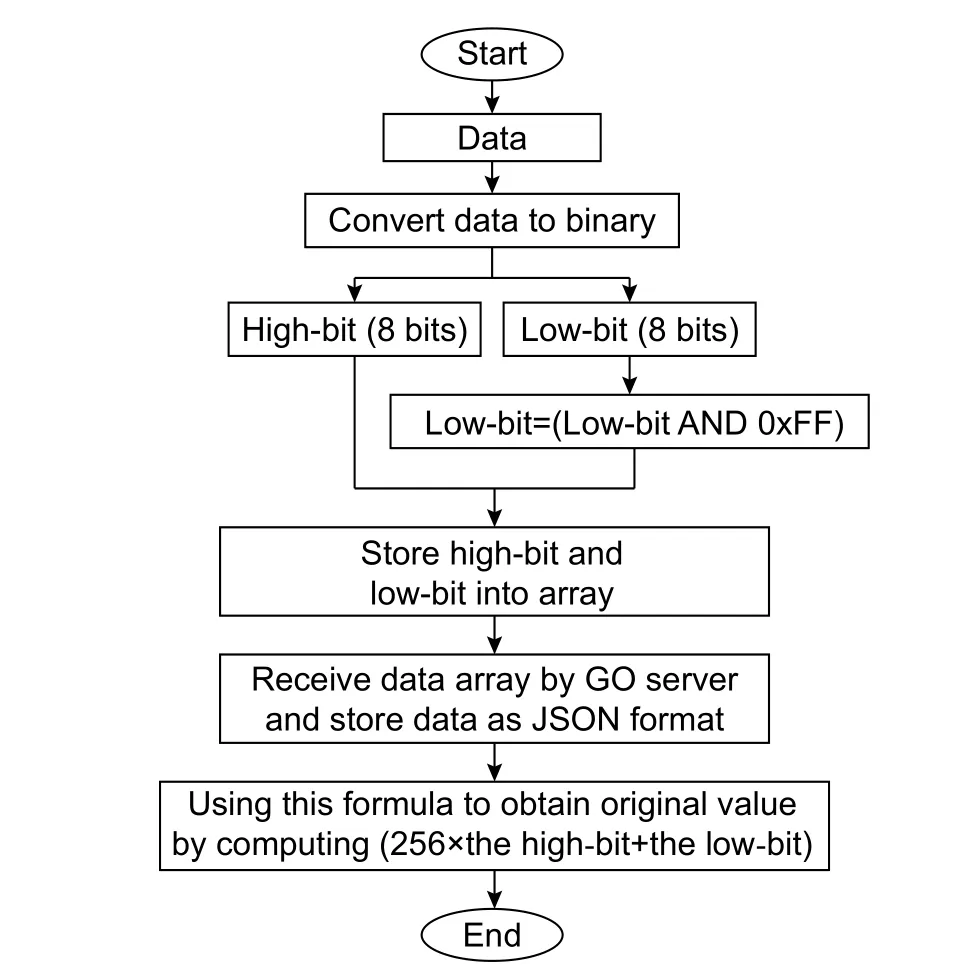
Fig.17.Flowchart of the NodeMCU transmission data method.
2.10.Server Construction
The GO language is a new programming language appeared in recent years.This language combines the advantages of many other programming languages,such as PHP, JavaScript, and Java.The thread can be executed in GO with only one line of codes.The GO language is set up in the server to receive data from NodeMCU.These data are stored in the JSON format for the PHP web page to obtain and calculate them.
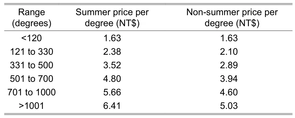
Table 3:Taipower electricity charging policy
2.11.Electricity Amount Enquiry
This experiment is used to provide consumers with details about the amount of money they spent every month on the electricity provided by the Taipower policy.In this way, they can control and save their money in advance.The web page calculates and displays the amount according to the Taipower charging policy, which is different in summer and non-summer, and the amount of each degree required for each degree range, as presented in Table 3.
3.Results and Discussion
A hardware device (shown in Fig.18) and software were built and implemented to monitor home appliances.
The measurement results obtained from the proposed monitoring device are displayed through a web page.This page contains information, such as the real frequency, RMS voltage, RMS current, PF, degree per second, degree per hour, alarm (an early warning system based on PF), and charts (RMS voltage, RMS current, phase difference, and PF).The web page display is shown in Fig.19.
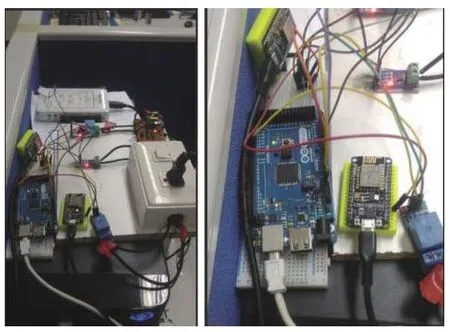
Fig.18.Hardware of the monitoring device.
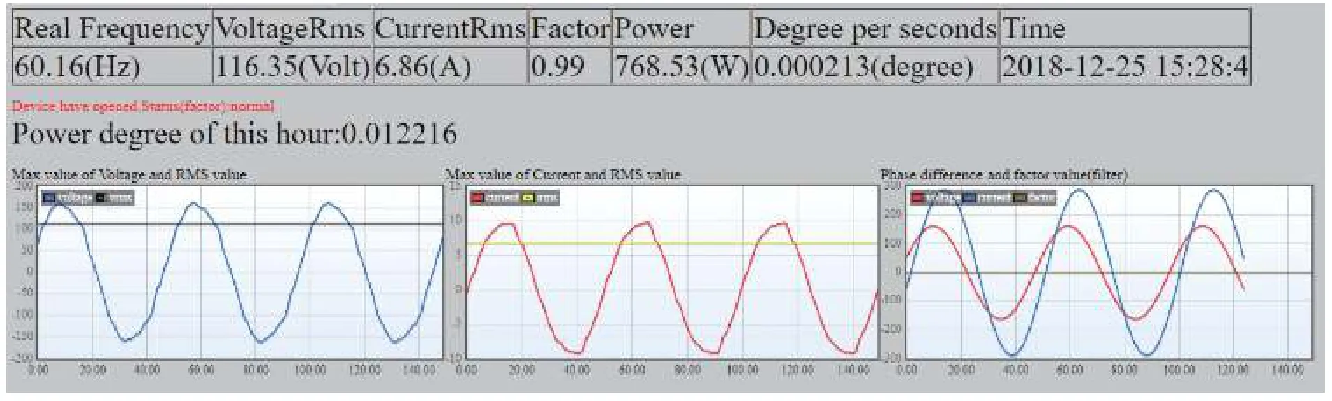
Fig.19.Measurement and calculation displayed on a web page for a hair dryer.
This system also displays information about the electricity usage degree and charges based on the Taipower charging policy, as shown in Fig.20.
Finally, the system was compared with a power measurement standard device (HIOKI PW3360) to estimate the measurement error.In this case, both the proposed system and HIOKI measured the hair dryer performance.The results are presented in Table 4.
From Table 4, it can be observed that the error percentages of the RMS voltage, RMS current, real frequency, and PF are small.
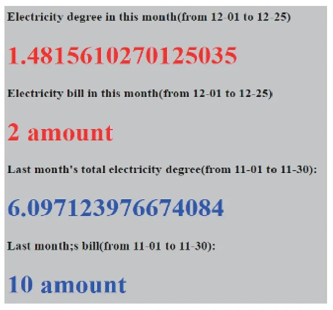
Fig.20.Display of the amount of degrees.
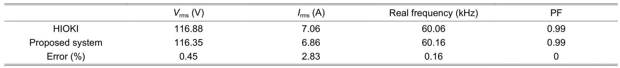
Table 4:Comparison between HIOKI and the proposed system
4.Conclusion
In this paper, a household electricity-measurement system based on IoT was developed to monitor the voltage,current, and PQ factor.The limitation of the Arduino related to data transfer was handled by NodeMCU (TCP communications technology).An approach in the NodeMCU coding was used to decrease data loading by implementing binary conversion and then dividing the data into high-bit and low-bit parts.Furthermore, the filtering model was adopted to filter the noise and achieve the filtering effect.After filtering, the real frequency calculation was performed, and the zero-cross algorithm was applied to calculate the total period of one cycle, which was divided by the sampling frequency to obtain the real frequency value.PF used three variables to find the trough in one cycle, applied the formula to calculate the phase, and then determined the phase difference.PF was calculated using the cos (Φ) formula.Finally, by comparing the proposed system and HIOKI, an IoT system at a low cost, which has the same function as the HIOKI measurement device, can be established.
Acknowledgment
The authors gratefully acknowledge the helpful comments and suggestions of the reviewers for improving the presentation.
Disclosures
The authors declare no conflicts of interest.
杂志排行

Journal of Electronic Science and Technology的其它文章
- Approach for Grid Connected PV Management:Advance Solar Prediction and Enhancement of Voltage Stability Margin Using FACTS Device
- Comparative Study of 10-MW High-Temperature Superconductor Wind Generator with Overlapped Field Coil Arrangement
- Characteristic Length of Metallic Nanorods under Physical Vapor Deposition
- Computational lntelligence Prediction Model lntegrating Empirical Mode Decomposition,Principal Component Analysis, and Weighted k-Nearest Neighbor
- Data Bucket-Based Fragment Management for Solid State Drive Storage System
- ECC-Based RFlD Authentication Protocol